Introduction
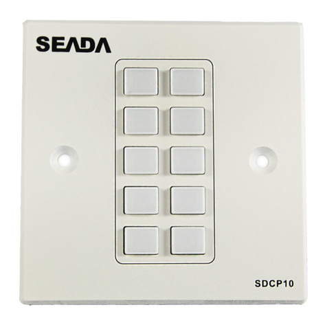
TheZoneOmitUnitallowseitheramonitoredalarmzone
and tamper zone to be isolated OR two monitored
alarmzonestobeisolated,sothattheywillnotgenerate
an alarm at the control panel if triggered. The omitted
condition will be indicated at the Zone Omit Unit. An
isolated zone can only be switched back to the normal
condition provided it is not in alarm (Safe Set).
Two versions of the Zone Omit Unit are available:
5158.2:
This version is supplied without a keyswitch,
therefore a remote keyswitch must be provided
so that the unit may be controlled. A Shunt Lock
switch may be used as the control switch.
5158S.2:
This version is supplied complete with integral
keyswitch and 2 keys.
Features
The Zone Omit Unit may be set to operate in one of two
modes:
Mode 1:
This mode allows one alarm zone and one
tamper zone to be isolated.
Mode 2:
This mode allows two alarm zones to be isolated
and two tamper zones to be monitored but not
isolated.
Theinternalpiezosoundermaybeselectedtosoundon
Isolate or Fault conditions.
Terminals are provided for the connection of remote
indicator LED's and an extension piezo sounder (Not a
loudspeaker).
Operation
Normal:
TheswitchissettotheONpositionandallLED'sare
off. The Zone and Tamper outputs to the control
panel will follow the condition of the connected
alarm and tamper zone inputs. If the alarm zone
is activated the alarm relay will open and the
condition will be indicated to the control panel. If
thetamper zone isactivated the tamperrelay will
open and the condition will be indicated to the
Control Panel.
Isolated:
The switch is set to the OFF position, this will be
indicatedbythegreenLEDilluminating.IfMODE1
is selected the alarm zone [ALM A] and tamper
zone[TMPA]areisolated fromtheControlPanel. If
MODE 2 is selected the alarm zone A [ALM A] and
alarm zone B [ALM B] are isolated.
Return to
Normal:
The unit can only be switched back to normal
(ON) when the monitored zones are healthy. If a
fault is present when turning the keyswitch to the
ON position the internal sounder will operate and
the appropriate Red Fault LED illuminates. If the
switch is left in the ON position the Red Fault LED
will extinguish when the fault is cleared, but the
sounder remain on. Once the fault has been
cleared,turningtheswitchtotheOFFpositionand
back to the ON position will reinstate the isolated
zone(s).
Specifications
Supply Voltage: 9 to 14V dc
Supply Current: 30mA to 33mA
Dimensions: 5158.2 -
127W x 182H x 32D mm
5158S.2 -
127W x 182H x 37D mm
Control Switch: ON - Zones Active
OFF - Zones Isolated
ComplieswiththerequirementsofBS4737:Part1:1986
496531 Issue A 1of4 5158.2 & 5158S.2
5158.2 & 5158S.2
5158.2 and 5158S.2 Installation Guide
