English Installation Instruction
Before starting to install and work with this device, please read the Safety
Instructions.
1 Scope of delivery
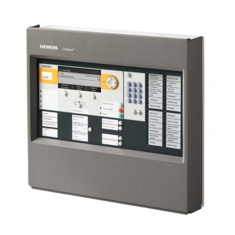
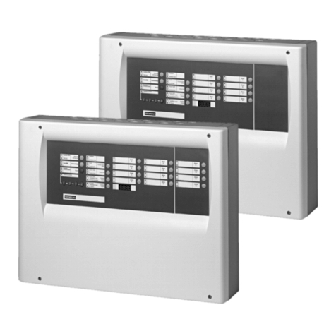
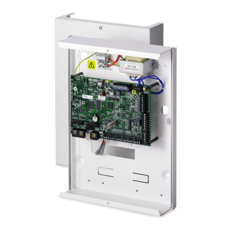
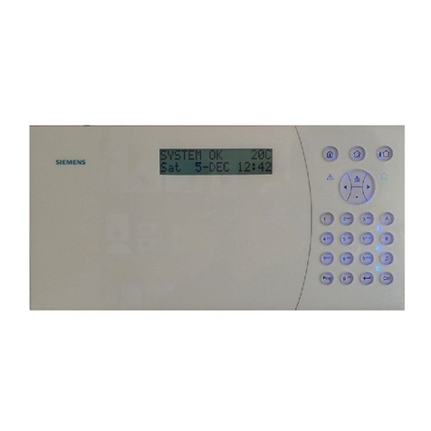
•IC60-W-10 Compact Control Panel
•Screws for mounting (a)
•Screws for closing detector (b)
•Plugs (c)
•3 packages of EOL resistors: 8x2,2K; 8x4,7K; 8x8,2K (d)
•Rubber band
•Battery pack NiMh 12 V / 1.8 Ah
Installation
2 Removing the cover
¾Loosen the retaining screws.
¾Carefully lift the casing cover manually
¾Remove the cover and the lexan inlay cover.
Option: Vertical installation
Use vertical kit IVK-6 for vertical installation of the control unit (containing of
vertical lexan inlay and vertical buttons). The vertical kit has to be ordered
separately.
3 Mounting the base
¾The base can be removed by applying pressure to the fastening axis (a)
while simultaneously pushing the plate upward on the back side.
¾Insert the wires into the opening on the base (b).
¾Fasten the base to the wall by using the 4 included screws and plugs.
¾Use the build in spirit level to position the base correctly. For additional help
see the enclosed drawing of the drilling plate.
4 Connecting the power cable
¾Break the strain relief bracket out of the casing (a).
¾Insert the power cable in the holes intended for this on the back of the
device.
¾Fasten the power cable with the strain relief bracket and the included
screws (b).
¾Connect the main and ground wires of the power cable with the
corresponding connections of the power terminal (110 - 250 V AC) (c).
5 Mounting the control unit on the wall
¾Insert the wires in the opening intended for this purpose in the casing (a).
If additional space is needed use the break out openings marked
“KNOCKOUT”.
¾Slide the control unit onto the mounting plate until it locks.
¾Fasten the screws in the panel indicated with “LOCK BRACKET”.
¾Set up the tamper detection: set the distance to the wall using the
screwdriver so that the tamper detection contact is completely closed (b).
6 Cable connections, adjustment bridges
Refer to the Installer Manual for detailed information pertaining to connection
options.
P1 LCD plug
P1 Vertical LCD position
P2 Programming plug
P2 Plug for memory stick or programming cable
J1 JUMPER keyboard alignment
J1 □■■ Horizontal keyboard alignment
■■□ Vertical keyboard alignment
J2 JUMPER switch-on voltage, relay B
J2 □■■ 0V
■■□ 12V
□□□ The relay contact is not grounded without a jumper
J3 JUMPER internal siren
J3 ■■Internal siren. During installation we recommend to disconnect this cable, which
will shut of the internal siren. Do not forget to reconnect before closing the housing,
J4 JUMPER tamper line
J4 □■■ Tamper contact activated
■■□Tamper contact deactivated
This is used only for the tamper for external cabling. The build in tamper of the unit can not
be deactivated
7 Connecting the battery
¾Insert the rubber band (a).
¾Insert and fasten the battery.
¾Connect the battery cable to the PCB (b).
Technical Data
Power supply 100-240 V AC, 50 / 60 Hz
Main fuse T250 mA
Power consumption max. 120 mA
Power supply output 12 VDC / 1 A
Battery type (optional) Ni-Mh12 V DC / max. 1800 mAh
Inputs 8+1
Outputs 1 x Relay 24 V DC / 2A
2 x OC 12 V DC / 1A
Frequency 868 MHz / 915 MHz
Operating temperature 0 ~ +50 °C
Housing material ABS
Complies with: EN 50131-1, TS 50131-3, EN 50130-4, EN 50130-5, EN 50131-6,
EN 50131-5-3, EN 50136-1-1, EN 50136-2-1
For more detailed instructions please refer to the manuals which can be
downloaded from the internet: www.siemens.com/homesecurity
Deutsch Installationsanleitung
Lesen Sie vor der Installation und Verwendung dieses Geräts die
Sicherheitshinweise.
1 Lieferumfang
•IC60-W-10 Funkalarmzentrale
•Schrauben für die Montage (a)
•Schrauben zum Schließen der Zentrale (b)
•Dübel (c)
•3 Packungen EOL Widerstände: 8x2,2K; 8x4,7K; 8x8,2K (d)
•Gummiband
•Baterrieeinheit NiMh 12 V / 1.8 Ah
Installation
2 Gehäuse öffnen
¾Die Schrauben 1-4 mit einigen Umdrehungen lösen.
¾Den Gehäusedeckel mit dem Schraubenzieher vorsichtig anheben
¾Den Deckel und die Lexaneinlage entfernen.
Option für Vertikalmontage:
Für die Vertikalmontage der Zentrale das Vertikal-Kit
IVK-6 verwenden.
3 Montageplatte befestigen
¾Die Montageplatte wird durch Druck auf die Befestigungslasche (a) und
gleichzeitiges Hochschieben der Platte auf der Rückseite entfernt.
¾Drähte durch die Öffnung der Montageplatte (b) führen.
¾Die Montageplatte mit den 4 mitgelieferten Schrauben und Dübeln an der
Wand befestigen.
¾Verwenden Sie die eingebaute Wasserwaage zum Ausrichten der Platte.
4 Stromkabel verbinden
¾Zugsicherungsklammer aus dem Gehäuse ausbrechen (a)
¾Das Netzkabel in die dafür vorgesehenen Aussparungen auf der Rückseite
des Gerätes einlegen.
¾Das Netzkabel mit der Zugsicherungsklammer und den mitgelieferten
Schrauben fixieren (B).
¾Die Drähte P,N und E des Stromkabels mit den korrespondierenden
Anschlüssen der Netzanschlussklemme (250VAC) verbinden (c).
5 Zentrale an der Wand montieren
¾Drähte durch die vorgesehenen Aussparungen (Break out holes) in das
Gehäuse führen.
¾Zentrale in die Montageplatte schieben, bis sie einrastet.
¾Ziehen Sie die Schrauben in der Zentrale, welche mit “LOCK BRACKET”
markiert sind, fest.
¾Mit einem Schraubenzieher die Distanz zur Wand so einstellen, dass der
Sabotagekontakt sauber schließt (b).
6 Kabelanschlüsse, Einstellbrücken
Detaillierte Informationen zu den Anschlussmöglichkeiten sind im
“Referenzhandbuch“ enthalten.
P1 LCD Stecker
P1 Vertikales LCD Bedienteil
P2 Programmieranschluss
P2 Anschluss für Programmieradapter oder externen Programmierspeicher
J1 JUMPER Bedienteilausrichtung
J1 □■■ horizontale Ausrichtung
■■□ vertikale Ausrichtung
J2 JUMPER Einschaltspannung Relais B
J2 □■■ 0V
■■□ 12V
□□□ Ohne Jumper ist der Relaiskontakt erdfrei
J3 JUMPER Innensirene
J3 ■■Innensirene ein, Wir empfehlen während der Installationsarbeiten die Sirene zu
deaktivieren.
J4 JUMPER Sabotagelinie
J4 □■■ Sabotagekontakt aktiviert
■■□ Sabotagekontakt deaktiviert
Beinflusst nur die Sabotageauslösungen von externen verkabelten Komponenten. Der
Zentralen Sabotagekontakt kann nicht deaktiviert werden.
7 Batterie einsetzen
¾Das Gummiband einschlaufen (a).
¾Batterie einsetzen und fixieren.
¾Batteriestecker mit der Zentrale verbinden (b).
Technische Daten
Spannungsversorgung 100-240 V AC, 50 / 60 Hz
Hauptsicherung T250 mA
Stromaufnahme max. 120 mA
Ausgangsleistung 12 VDC / 1 A
Batterietype (optional) Ni-Mh12 V DC / max. 1800 mAh
Eingänge 8+1
Ausgänge 1 x Relais 24 V DC / 2A
2 x OC 12 V DC / 1A
Frequenz 868 MHz
Betriebstemperatur 0 ~ +50 °C
Gehäusematerial ABS
Erfüllt die Anforderungen folgender Richtlinien: EN 50131-1, TS 50131-3,
EN 50130-4, EN 50130-5, EN 50131-6, EN 50131-5-3, EN 50136-1-1,
EN 50136-2-1
Ausführlichere Informationen finden Sie in den Handbüchern, die Sie unter
folgender Adresse aus dem Internet herunterladen können:
www.siemens.com/homesecurity
Français Instructions d'installation
Avant de commencer l’installation de ce produit, merci de prendre
connaissance des consignes de sécurité.
Contenu de l’emballage
•Centrale IC60-W-10
•Vis pour montage(a)
•Vis pour fermeture des détecteurs (b)
•Chevilles (c)
•3 packs de résistances: 8x2,2K; 8x4,7K; 8x8,2K (d)
•Elastique
•Pack de batterie NiMh 12 V / 1.8 Ah
Installation
2 Ouverture du boitier
¾Dévisser les vis sans fin.
¾Soulever délicatement le capot du boitier
¾Retirer le capot et le lexan.
Option: Installation verticale
Utiliser le kit de montage vertical IVK-6 pour une installation verticale de la
centrale (contient le lexan vertical, et les boutons verticaux). Le kit vertical est à
commander séparément.
3 Fixer la base
¾La base peut être retirée en appuyant sur le clip, tout en poussant la base
vers le haut.
¾Faire passer les câbles dans le trou de la base (b).
¾Fixer la base sur le mur en utilisant les 4 vis et chevilles fournies.
¾Utiliser le niveau à bulle inclus pour positionner la base correctement. Pour
une aide supplémentaire, voir le schéma de l’embase fournie avec la
centrale.
4 Raccorder l’alimentation
¾Détacher la pièce de plastique servant à maintenir le câble d’alimentation
(a).
¾Insérer le câble d’alimentation dans le trou prévu à cet effet à l’arrière de la
centrale.
¾Sécuriser le câble d’alimentation avec la pièce de plastique détachée
précédemment, et avec les vis fournies. (b).
¾Raccorder l’alimentation et la masse du câble d’alimentation sur les bornes
correspondantes (110 - 250 V AC).
5 Monter la centrale sur le mur
¾Insérer les câbles dans l’emplacement prévu à cet effet (a).
Si l’emplacement n’est pas suffisant, utiliser les emplacements prédécoupés
marqués “KNOCKOUT”.
¾Faire glisser la centrale sur l’embase jusqu’à la fermeture.
¾Sécuriser la centrale en vissant les vis à l’endroit indiqué “LOCK BRACKET”.
¾Régler le contact d’autoprotection à l’arrachement : régler la distance au mur
en utilisant un tournevis afin que le contact d’autoprotection soit
complètement fermé (b).
6 Branchement des câbles et réglages des cavaliers
Se reporter au manuel d’installation pour plus d’informations.
P1 Connecteur pour écran LCD
P1 Ecran LCD en position verticale
P2 Slot de paramétrage
P2 Slot pour clé mémoire ou câble de paramétrage
J1 Cavalier pour orientation clavier
J1 □■■ Clavier orienté horizontalement
■■□ Clavier orienté verticalement
J2 Cavalier pour tension du relais (sortie N°4)
J2 □■■ 0V
■■□ 12V
□□□ Aucune tension n’est reliée au commun du relais.
J3 Cavalier sirène intégrée
J3 ■■Sirène intégrée. Durant l’installation, il est recommandé de débrancher ce câble. Ne
pas oublier de le rebrancher avant de refermer la centrale,
J4 Cavalier entrée d’autoprotection
J4 □■■ Autoprotection activée
■■□ Autoprotection désactivée
Ceci est à utiliser uniquement pour un câblage externe (détecteurs filaires, sirènes, …). Le
contact d’autoprotection de la centrale ne peux pas être désactivé.
7 Raccordement de la batterie
¾Insérer l’élastique (a).
¾Insérer et sécuriser la batterie.
¾Raccorder la batterie à la carte électronique (b).
Données techniques
Alimentation 100-240 V AC, 50 / 60 Hz
Fusible T250 mA
Consommation max. 120 mA
Sorite d’alimentation 12 VDC / 1 A
Batterie (en option) Ni-Mh12 V DC / max. 1800 mAh
Entrées 8+1 (autoprotection)
Sortie 1 x Relais 24 V DC / 2A
2 x CO 12 V DC / 1A
Fréquence radio 868 MHz
Température de fonctionnement 0 ~ +50 °C
Boitier ABS
Conforme aux normes: EN 50131-1, TS 50131-3, EN 50130-4, EN 50130-5, EN
50131-6, EN 50131-5-3, EN 50136-1-1, EN 50136-2-1
Pour des instructions plus détaillées, veuillez vous reporter aux manuels
téléchargeables de l'Internet sur le site : www.siemens.com/homesecurity.
