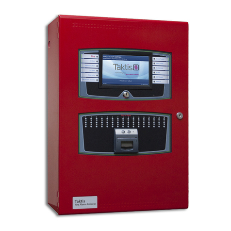
Kentec Electronics Taktis User manual

Taktis Fire Alarm ControlPanel
Installation Manual
UL Version 1.04 |May 2020 |MAN-1431KE

CONTENTS
Contents 2
Glossary 12
Compliance Information 14
Underwriters Laboratories (UL) 14
NFPA 14
FM Global Technologies LLC (FM APPROVALS) 14
Introduction 15
Technical Support 15
Return Material Authorization (RMA) 15
Warranty Service 16
Advanced Replacements 16
Installation 17
Preparing for Installation 18
Mounting the Taktis Fire Alarm ControlPanel 20
Removing Cabinet Components 20
Replacing Cabinet Components 23
Connecting and Dressing Cabling 23
Connecting 24V and 14 Conductor Wiring 23
Installing Power Supplies 23
The 5.25 Amp Power Supply 23
The 10.25 Amp Power Supply 25
Connecting Standby Batteries 25
Installing Optional Panel Modules 27
Taktis Fire Alarm ControlPanel Installation Manual
Kentec Electronics Ltd
Taktis Fire Alarm ControlPanel Installation Manual
UL Version 1.04 |May 2020 |MAN-1431KE
Page 2

DIP Switch Settings 27
Placement 27
Installing the Network Module 30
Network Connections 30
Fiber Optic Networking 31
Connecting Field Wiring 34
Wiring Diagram 35
Class A SLCLoops 37
Class B SLC Loops 38
Class X SLC Loops 39
Notification Appliances 39
Connecting Notification Appliances 40
Connections for NACPower Output Modes 41
Continuous Constant Power 41
Door Holder 42
Resettable 42
AUX 24V 1 and AUX 24V 2 42
Relay Contacts 43
Network 44
RS-485 I/O 44
Fire Routing Output 1 45
Prog Input 45
Routing I/O Terminals 47
Installing Addressable Devices 48
Kentec Electronics Ltd
Taktis Fire Alarm ControlPanel Installation Manual
UL Version 1.04 |May 2020 |MAN-1431KE
Page 3
Taktis Fire Alarm ControlPanel Installation Manual

SLC Detector Spacing 48
SLC Device Detector Sensitivity 48
Detector Calibration / Drift Compensation 48
Addressing an SLCModule 48
Hochiki Protocol 48
Connecting SLCDevices 48
Hochiki Protocol 49
Installing Municipal Boxes 51
Testing the Installation 52
Panel Start-up 52
Loading Configuration 53
Testing the Power Supply 53
Testing the Field Circuits 53
Testing the Panel GUI 54
Panel Tests 55
Lamp & Buzzer Test 55
Display Test 55
System Information 55
Event Log 56
Programming the Panel 57
Loop Explorer 2 57
Overview 58
Required Modules for Minimum Operation and Basic Function 60
System A Panel Module (S769) 60
Taktis Fire Alarm ControlPanel Installation Manual
Kentec Electronics Ltd
Taktis Fire Alarm ControlPanel Installation Manual
UL Version 1.04 |May 2020 |MAN-1431KE
Page 4

System B Panel Module (S770) 61
Dual Loop Panel Module (S758) 63
Notification Appliances 64
Synchronization 64
Configuring NAC Outputs 65
Optional Modules and Assemblies 66
Network Module (S723) 66
Printer (S768) 67
Zone LED Module (S771) 67
16 Channel I/O Interface Card (K1171) 68
Use Case Examples 68
Restrictions 69
16 Channel I/O Panel Module (S772) 70
Use Case Examples 70
Restrictions 70
Taktis Network Vision Annunciator (S787) 71
Media Gateway™ Panel Module (S788) 72
8 Channel Relay Panel Module (S791) 72
8 Channel Conventional Zone Panel Module (S792) 72
4 Channel NAC Panel Module (S793) 73
Batteries 74
Standby Battery Type 74
Fascia 75
LEDStatus Indicators 77
Kentec Electronics Ltd
Taktis Fire Alarm ControlPanel Installation Manual
UL Version 1.04 |May 2020 |MAN-1431KE
Page 5
Taktis Fire Alarm ControlPanel Installation Manual

Panel LEDs 77
Fire In Zone Indicators 77
Main Back Board (S722) 79
NAC and AUX 24V Terminals 81
Terminals 82
Panel Module Slots 83
Field Terminal Assignments 84
Panel Module Slots 85
Board Slot C 85
Board Slot D 85
Board Slot E 86
Board Slot F 87
Extension Board Power Terminals 88
Network, RS-485 I/O, Fire Routing Output 1, and Prog Input 89
Power Supply Terminals 90
0V Terminals 91
Power Supply Trouble Signaling Connector 91
Supervised Input and Output Terminals 92
Extension Board (S786) 93
Extension Board Features 95
Panel Module Slots and Terminals 96
Board Slot G, H, J, K 96
Slot G 97
Slot H 98
Taktis Fire Alarm ControlPanel Installation Manual
Kentec Electronics Ltd
Taktis Fire Alarm ControlPanel Installation Manual
UL Version 1.04 |May 2020 |MAN-1431KE
Page 6

Slot J 99
Slot K 100
Other Terminals 100
LCD Main Processor Board (S721) 101
Connectors and Ports 103
Switches, LED Indicators, and Internal Buzzer 104
19Inch Rack Mount Enclosure 105
Installation 107
Batteries 108
Connecting Field Wiring 109
Power Supply 111
Power Supplies 112
Features 113
DIPSwitches 113
5.25 Amp Power Supply 113
10.25 Amp Power Supply 115
Special Application Mode Table 116
Status Indicators 116
Events and Status 117
Fire 117
CO 118
Trouble 118
Supervisory 119
Disablement 119
Kentec Electronics Ltd
Taktis Fire Alarm ControlPanel Installation Manual
UL Version 1.04 |May 2020 |MAN-1431KE
Page 7
Taktis Fire Alarm ControlPanel Installation Manual

Other Events 120
Maintenance and Repair 121
Batteries 122
Replacing Battery Leads 122
Replacing Standby Batteries 122
Removing the Standby Batteries 122
Installing the Standby Batteries 122
Fuses 123
Battery Lead Fuse on 5.25A Power Supply 123
Replacing the Power Supply Fuse 123
Removing the Power Supply Fuse 123
Installing the Replacement Power Supply Fuse 124
Replacing Internal Components 125
Appendix A: Specifications 127
Operating Constraints 128
Electrical 129
AC Input Ratings 129
Power Supply 130
Fuses 130
24 VDC Output Ratings 130
StandbyBattery Ratings 130
Ground Trouble Indication 131
System Power 131
Standby and Alarm Current 131
Taktis Fire Alarm ControlPanel Installation Manual
Kentec Electronics Ltd
Taktis Fire Alarm ControlPanel Installation Manual
UL Version 1.04 |May 2020 |MAN-1431KE
Page 8

5.25 A Power Supply 131
10.25 A Power Supply 131
Battery 133
Rechargeable Standby Battery Circuit 133
Standby Battery Loads 133
Cabling 134
Cable Maximum Parameters for Network 134
RS-485 Serial Data and Terminal Capacity 134
SLC Loop Ratings 135
Main Back Board 136
NACOutputs 136
Regulated NAC Outputs 136
Special Application NAC Outputs 137
AUX 24V 138
Relay Ratings 139
Network (RS-485) 139
RS-485 I/O 139
Fire Routing Output 1 139
Prog Inputs 140
Fire Routing Input 140
Fire Routing Output 2 140
Prog Routing Input 1 140
Prog Routing Output 141
Prog Routing Input 2 141
Kentec Electronics Ltd
Taktis Fire Alarm ControlPanel Installation Manual
UL Version 1.04 |May 2020 |MAN-1431KE
Page 9
Taktis Fire Alarm ControlPanel Installation Manual

Trouble Routing Output 141
Trouble Routing Input 141
System Information 143
Mechanical 144
Fascia Components 144
Operating Environment 144
Cabinet Housing 145
4 Slot Standard Enclosure 146
8 Slot Standard Enclosure 147
4 Slot Deep Enclosure 148
8 Slot Deep Enclosure 149
19"Rack Mount 150
Appendix B: Equipment List 153
Panel Model Numbers 154
Replacement Parts 156
Accessories 158
Loop Devices 159
Special Application NAC Outputs 161
Amseco Compatible NAC Devices 161
Gentex Compatible NAC Devices 162
System Sensor Compatible NAC Devices 163
Wheelock Compatible NAC Devices 164
Maximum Line Impedance 172
Compatible Devices for Auxiliary 24V 172
Taktis Fire Alarm ControlPanel Installation Manual
Kentec Electronics Ltd
Taktis Fire Alarm ControlPanel Installation Manual
UL Version 1.04 |May 2020 |MAN-1431KE
Page 10

Appendix C: Calculations 173
SLC Loop Cabling 174
Example Voltage Drop Condition 174
Voltage-drop of the twin cable 174
Voltage at the load 175
14 AWG Cable 175
16 AWG Cable 177
18 AWG Cable 180
NAC Cabling 183
12 AWG Cable 183
14 AWG Cable 185
16 AWG Cable 186
AUX 24V Cabling 188
12 AWG Cable 188
14 AWG Cable 190
16 AWG Cable 193
Determining the Total Load Current 196
Determining the Standby Battery Capacity 197
Battery Rating Equation 197
Amp Hour Rating 198
Supervising Station Requirementsfor Combination Systems 200
Index 201
Kentec Electronics Ltd
Taktis Fire Alarm ControlPanel Installation Manual
UL Version 1.04 |May 2020 |MAN-1431KE
Page 11
Taktis Fire Alarm ControlPanel Installation Manual

GLOSSARY
SYMBOLS
W
Indicates a ground terminal
A
AHJ
Authority Having Jurisdiction. The government body, organization, office, or individual hav-
ing the power to enforce and/or interpret laws, codes, and rules.
Ancillary Device
A device connected to a fire alarm system not required by the fire alarm standard, but may
be required by other standards, e.g. door holders, smoke control fans, remote LED indic-
ators, remote alarm, or trouble units.
AWG
American Wire Gauge. The standard American designation of wire sizes. Wire size is an
inverse relation to gauge numbers that range from 0000 to 40 AWG. Also called Brown and
Sharpe or B&S gauge.
C
Class A
A wiring classification of circuits capable of transmitting an alarm signal during a single
open or non-simultaneous ground fault on a conductor.
Class B
A wiring classification of circuits NOT capable of ransmitting an alarm signal beyond a
single open or during a short between conductors.
Kentec Electronics Ltd
Taktis Fire Alarm ControlPanel Installation Manual
UL Version 1.04 |May 2020 |MAN-1431KE
Page 12
Taktis Fire Alarm ControlPanel Installation Manual

Class X
A wiring classification capable of transmitting an alarm signal during a single open, short, or
non-simultaneous ground fault on a conductor.
D
DIP Switch
A group of two-position electrical contacts mounted in a Dual Inline Package (DIP), typically
used to set address or function information.
E
End-Of-Line Device (EOL)
An electronic component physically installed as the furthest device from the control panel;
whose presence on the circuit is used to monitor the integrity of the circuit.
N
NAC
Notification Appliance Circuit. A supervised output circuit that connects horns, strobes,
speakers, etc. to the control panel.
S
SLC
Signaling Line Circuit. A Signaling Line Circuit (SLC) carries data to and from the field
devices for the fire alarm system, and also carries power from the control panel to the
devices.
Supervision
Monitoring the integrity of a circuit or device to detect a fault condition that would prevent nor-
mal operation.
Taktis Fire Alarm ControlPanel Installation Manual
Kentec Electronics Ltd
Taktis Fire Alarm ControlPanel Installation Manual
UL Version 1.04 |May 2020 |MAN-1431KE
Page 13

COMPLIANCE INFORMATION
Underwriters Laboratories (UL)
Fire Alarm Equipment
Kentec Electronics Ltd
The Taktis Fire Alarm ControlPanel is suitable as follows:
nTypes of signaling services are automatic fire alarm and manual fire alarm
nClass A, B, and/or X Signaling Line Circuits
nClass Aand/or B for Notification Appliance Circuits
nProtected Premises Unit (PPU) for Local Service, Remote Station Service, Center Station Service,
Proprietary Service, Auxiliary Service.
NFPA
Install this product in accordance with NFPA 72, NFPA70, and NEC 70 and all local codes.
Install SLC detectors with spacing as specified in section NFPA 72. Units employing "multiple detector
operation" shall include guidelines for installing of a minimum of two detectors in each protected space and to
reduce the detector installation spacing to 0.7 times the linear spacing in accordance with National Fire Alarm
Code, NFPA 72.
All field wiring should be installed using fire rated cables according to the NFPA 72. Riser conductors shall be
installed in accordance with the survivability from attack by fire requirements in National Fire Alarm Code, NFPA
72, Section 12.3. Riser conductors shall employ either a 2 hour rated cable system, or meet requirements
approved by the AHJ.
FM Global Technologies LLC (FM APPROVALS)
Kentec Electronics Ltd
Taktis Fire Alarm ControlPanel Installation Manual
UL Version 1.04 |May 2020 |MAN-1431KE
Page 14
Taktis Fire Alarm ControlPanel Installation Manual

INTRODUCTION
Technical Support
For technical support, contact Kentec Electronics, Ltd at +44 (0)1322 222121 or techsupport@kentec.co.uk.
Prior to contacting technical support, have the following information available:
nProduct part number
nPurchase order or order number
nProduct serial number
nCurrent function of the product
nExpected function of the product
nInstallation of the product
Return Material Authorization (RMA)
Contact Technical Support to obtain an RMAfor any product to be returned. Returns will not be accepted
without an accompanying RMA number. An RMA number is assigned when:
lTech Support acknowledges a possible product failure.
lA product was damaged during shipping
lAn incorrect product was shipped
lAn order was placed using an incorrect part number *
lAn order was placed using an incorrect part quantity *
lAn order is no longer required *
* Restocking fees may apply.
All returned products are tested to confirm operating failures experienced in the field. If the product is found to be
functional, contractors must absorb expenses for return shipping, as well as the cost and shipping of the
advanced replacement product.
Prominently display the RMA number on all packages sent for return.
Ship all return products to:
Taktis Fire Alarm ControlPanel Installation Manual
Kentec Electronics Ltd
Taktis Fire Alarm ControlPanel Installation Manual
UL Version 1.04 |May 2020 |MAN-1431KE
Page 15

Attention: RMA # _____________
Kentec Electronics, Ltd
Units 25-27 Fawkes Avenue
Questor, Dartford
Kent. DA1 1JQ
United Kingdom
Warranty Service
Technical Support can replace or repair a defective product when the original purchase is within the warranty
period defined in the sales contract. Check your contract for more information, or contact your sales
representative about your specific warranty period.
Advanced Replacements
Products that fail to operate in the field can be replaced quickly using the advanced replacement process. The
advanced replacement process is available to all contractors who maintain an acceptable line of credit.
Initiate the advanced replacement process by requesting an RMA number from a Tech Support representative.
Advanced replacements can be shipped to your location when the product is covered under warranty and when
a replacement product is in stock.
lAdvanced replacements can be expedited at the request of the contractor. Shipping costs associated with
this process are the responsibility of the contractor.
lProducts returned using the advanced replacement process must be received within 30 days of the RMA
issue date.
Kentec Electronics Ltd
Taktis Fire Alarm ControlPanel Installation Manual
UL Version 1.04 |May 2020 |MAN-1431KE
Page 16
Taktis Fire Alarm ControlPanel Installation Manual

INSTALLATION
This section provides instructions for connecting cables, mounting, and testing the Taktis Fire Alarm
ControlPanel for installation. The following is a general checklist for the installation of the panel. Detailed
instructions are provided for each step.
WARNING! Disconnect AC and battery power before making any field connections.
Double-check all termination points before applying power to the panel! Incorrectly
terminated wiring may cause permanent damage to the panel.
IMPORTANT! The Taktis Fire Alarm ControlPanel installation must be performed by qualified service personnel.
Maintain extreme care when anchoring the cabinet to the premises wall. Electronic components within the panel are
vulnerable to physical damage from severe shock and vibration. Remove the cabinet door and fascia for the
installation of the panel. Detailed instructions are provided for each step.
Task
qObtain required mounting hardware, tools, and batteries.
qDisconnect ribbon and ground cables.
qOpen and remove the fascia from the cabinet.
qOpen and remove the door from the cabinet.
qRemove the backplate and any installed batteries from the cabinet.
qAnchor the empty cabinet to the premises wall.
qThread the cabling into the cabinet.
qReattach the backplate to the cabinet.
qSecure the cabling to the terminals.
qPlace standby batteries in the base of the cabinet and connect them to the power supply.
qReconnect the ribbon and ground cables.
qReattach the fascia and door.
qApply power to the panel from the AC source.
qProgram the panel.
qTest the installation.
Taktis Fire Alarm ControlPanel Installation Manual
Kentec Electronics Ltd
Taktis Fire Alarm ControlPanel Installation Manual
UL Version 1.04 |May 2020 |MAN-1431KE
Page 17

Preparing for Installation
1. Refer to the checklist provided above before beginning the installation process. For detailed information,
refer to the appropriate, referenced section in this document.
2. Select a suitable operation environment. The site should be clean, dry, and not subject to shock or
vibration. Ensure that the environment is free from wire ends, knockout tabs, and other debris.
3. Familiarize yourself with the panel and components.
Item Description
Power Supply Depending on the model, the Taktis Fire Alarm ControlPanel will have either a 5.25 Amp or
10.25 Amp power supply.
Main Back Board
The Main Back Board contains slots for six circuit boards, and accepts the System A Panel
Module, System B Panel Module, Dual Loop Panel Module(s), and various optional panel
modules.
LCD Main Processor Board The LCD Main Processor Board provides operation of the panel GUI.
System A Panel Module System A Panel Module is required for operation of the fire alarm control panel. All models of
the Taktis Fire Alarm ControlPanel contain one System A Panel Module.
Kentec Electronics Ltd
Taktis Fire Alarm ControlPanel Installation Manual
UL Version 1.04 |May 2020 |MAN-1431KE
Page 18
Taktis Fire Alarm ControlPanel Installation Manual

Item Description
System B Panel Module System B Panel Module is required for operation of the fire alarm control panel. All models of
the Taktis Fire Alarm ControlPanel contain one System B Panel Module.
Dual Loop Panel Module
The Dual Loop Panel Module provides two addressable loop functions for the fire alarm
control panel. All models of the Taktis Fire Alarm ControlPanel contain at least one Dual
Loop Panel Module.
Ground Cable(s) Ground cabling is green and yellow, insulated wire containing connecting lugs. Ground
cabling provides common electrical grounds of the cabinet to the lid, fascia, and backplate.
14 Conductor PSU Cable The 14 Conductor PSU Signal Cable connects from the power supply to the Main Back
Board.
34 Conductor Cable The 34 Conductor Cable connects the Main Back Board to the LCD Main Processor Board.
40 Conductor Cable The 40 Conductor Cable connects the Main Back Board to the LCD Main Processor Board.
10 Conductor Zone LED
Cable
(optional)
The 10 Conductor Zone LED Cable connects from the Zone LED Module to the LCD Main
Processor Board.
10 Conductor Zone LED to
LED Cable (optional)
The 10 Conductor Zone LED to LED Cable connects from one Zone LEDModule to the next
Zone LEDModule. This cable is required when two or more Zone LEDModules are installed
on the fascia.
10 Conductor Printer Cable
(optional)
The 10 Conductor Printer Cable connects the printer assembly to the LCD Main Processor
Board.
4. The following items are not included with the Taktis Fire Alarm ControlPanel, but may be required for the
installation:
lTwo 12 VDC VRLA (Valve-Regulated Lead Acid) Standby Batteries - Required
lMounting Hardware - Mounting hardware that secures the panel to the wall is not provided. Screws
should be either a #10 or #12.
lA Ground Strap is required for handling circuit boards.
Taktis Fire Alarm ControlPanel Installation Manual
Kentec Electronics Ltd
Taktis Fire Alarm ControlPanel Installation Manual
UL Version 1.04 |May 2020 |MAN-1431KE
Page 19

Mounting the Taktis Fire Alarm ControlPanel
IMPORTANT! Electronic components within the panel are vulnerable to damage from electrostatic discharge.
Ground straps must be worn by installers before handling circuit boards to prevent damage from electrostatic
discharge.
Mount the cabinet box on a flat, dry surface and align it so that it is at eye-level with the center of the panel GUI.
Use the cabinet box as a template and mark the position of the mounting holes while ensuring that the wall is flat
at the chosen location.
The Taktis Fire Alarm ControlPanel must be mounted in an accessible location. It must not be mounted in
another enclosure or near sources of excessive heat. The Taktis Fire Alarm ControlPanel is intended for indoor,
dry use only.
Use knockout tabs of the cabinet box to route external cabling into the panel.
IMPORTANT! Drilling additional holes in the cabinet will void the product warranty.
Removing Cabinet Components
Remove the fascia, lid, backplate, and batteries before mounting the cabinet box. The fascia contains the LCD
Main Processor Board and, optionally, Zone LED indicators and a printer. The backplate contains the Main Back
Board, power supply, and grounding terminals. To remove these components:
1. Disconnect the four ground jumper cables from the cabinet.
Kentec Electronics Ltd
Taktis Fire Alarm ControlPanel Installation Manual
UL Version 1.04 |May 2020 |MAN-1431KE
Page 20
Taktis Fire Alarm ControlPanel Installation Manual
Other manuals for Taktis
3
Table of contents
Other Kentec Electronics Control Panel manuals
Kentec Electronics
Kentec Electronics Sigma XT K11031F2 User manual

Kentec Electronics
Kentec Electronics Sigma ZXT User manual

Kentec Electronics
Kentec Electronics Sigma CP K Series User manual

Kentec Electronics
Kentec Electronics Taktis User manual

Kentec Electronics
Kentec Electronics Syncro ASM User manual

Kentec Electronics
Kentec Electronics Syncro User manual
Kentec Electronics
Kentec Electronics Solo 2 Lite Guide

Kentec Electronics
Kentec Electronics Syncro Focus User manual

Kentec Electronics
Kentec Electronics Sigma ZXT User manual
Kentec Electronics
Kentec Electronics Sigma ZXT User manual