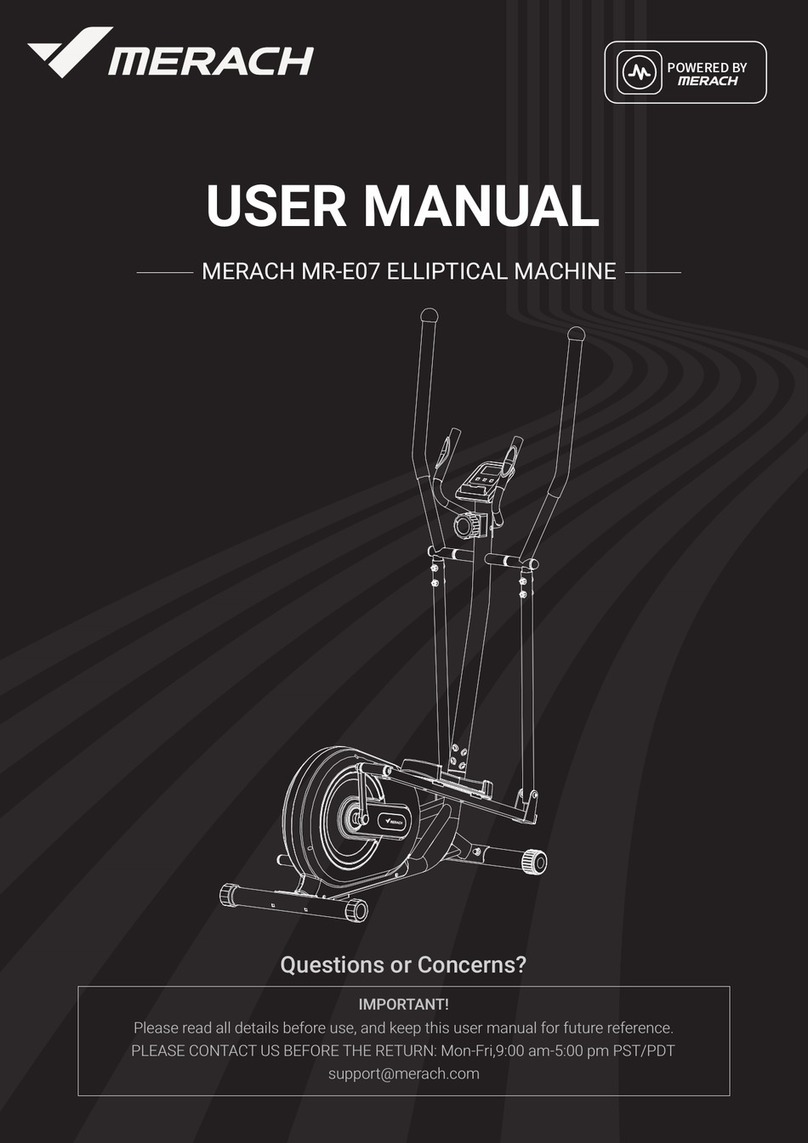
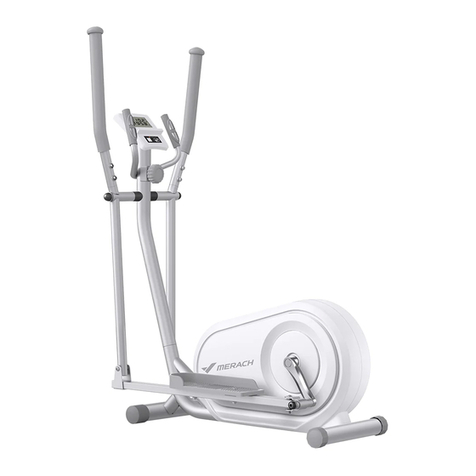
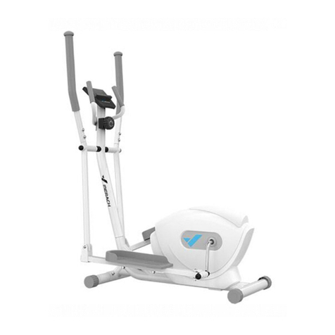
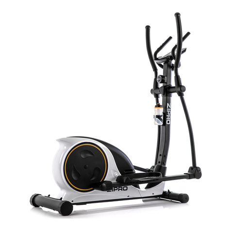
Merach MR-526 User manual

MR-526
ELLIPTICAL TRAINER
INSTRUCTION MANUAL
Email:service@merach.com
Official Website: www.merach.com
Company: Zhejiang Yulu Electronic Technology Co., Ltd.
Address: 298 Weiye Road, Binjiang District, Hangzhou,
Zhejiang Province, China

MR-526 ELLIPTICAL TRAINER
INSTRUCTION MANUAL

Dear Customers,
We want to thank you for having chosen an Elliptical trainer and wish you a lot of
fun and success during training.
Please note and follow the enclosed safety and assembly instructions carefully.
If you have questions please do not hesitate to contact us.
Support email:[email protected].
Safety Instruction ...................................2-3
Exploded Drawing ....................................4
Parts List .........................................5-7
Installation Steps ...................................8-13
Operation instruction of multifunctional sports monitor ......14-16
Table of Content as below

2
Before you start training on your home Elliptical trainer, please read the instructions
carefully. Be sure to keep the instructions for information, in case of repair and for
spare part delivery.
This elliptical trainer is made for home use only and tested up to a maximum body
weight of 350lb.
Follow the steps of the assembly instructions carefully.
For assembly use only suitable tools and asks for assistance with assembly if
necessary.
Check before the first training and every 1-2 months that all connecting elements
are tight fitting and are in the correct condition. Replace defective components
immediately and/or keep the equipment out of use until repair. For repairs, use only
original parts.
In case of repair, please ask your dealer for advice.
Avoid the use of aggressive detergents when cleaning the home exerciser.
Ensure that training starts only after correct assembly and inspection of the item.
For all adjustable parts be aware of the maximum positions to which they can be
adjusted/tightened to.
The home exerciser is designed for adults. Please ensure that children use it only
under the supervision of an adult.
SAFETY INSTRUCTION

■Ensure that those present are aware of possible hazards, e.g.
movable parts during training.
■Consult your physician before staring with any exercise program.
He or she can advise on the kind of training and which impact is
suitable.
WARNING!INCORRECT/EXCESSIVE
TRAINING CAN
CAUSE HEALTH INJURIES.
■Please follow the advice for correct training as detailed in training
instructions.
■The load/work level can be adjusted by turning the adjustment
knob on the handle bar stem.
■The safety level of this equipment can be maintained only if it is
check regularly for all assembly procedure mentioned in the
assembly instruction sheet.
■Please check regularly for the tightening knobs to notice any
irregular wear.
3

EXPLODED DRAWING
4
16
9L
10
11 12 13
15
14
17
21
22 23 24
26 27
9R
25L
34R
36R
40
18
41
89
90
91L
92
74 75 76 58 57 56
86
88
87
85
84
32
31
30
Item.99*2
Item.100*1
28
29
44R 45
42
43
46
20
48
49
50
53
64
65
67 68 69 70
63
71 72 73
77 78 79
80
81
82
83
91R
95
94
60
61 62
47
55
51
54
19
33
34L
35
36L
39
38
37
1
2
3
4
5
6
8
7
25R
59
66
93
96
99
100
44L
52
98
97

MR-526 Components and Parts List
No
Product name
Specification
Material
Quantity
1 Electronic meter
JS-10327 outgoing line 120MM, two heartbeat outgoing line
100MM
1
2
Hand-held heartbeat
sheet
Flexible rubber 2
3
Handle weld
∅
25
FE
1
4
Cup head self-tapping
screw
M4*20 BK 2
5
Semi-round end cover
∅
25
PP
2
6
Foam
∅
25*3T*500mml
HDR
2
7
End cover
∅
50*32 upper swing pipe with a small top ring
PP
2
8
Foam
32*3t*570MML upper swing pipe
HDR
2
9R
Upper swing right
∅
32*1.5T*752MML
FE
1
9L
Upper swing left
∅
32*1.5T*752MML
FE
1
10
Umbrella-head
inner-hexagon screw
M8*20 Nylonpatch 360°, 5MM handle 2 + central axis 2 +
crank spindle 2
Plating black
6
11
Spring washer
∅
8 pedal spindle 2 + central axis 2 + handlebar 6
Plating black
10
12
Spring washer
8*36*3 central axis
Plating black
2
13
Nylon bush
18.8*38 outer ring without groove
PA+MnS2
4
14
Curved washer
8*19*1.5T upper swing pipe 4+ handlebar 6+ handle 2
Plating black
12
15
Umbrella-head
inner-hexagon screw
M
8*20 5mm Upper swing with hexagon hole 4 + handlebar 6
Plating black
10
16
Spring washer
∅
19.5*
∅
38*0.5
BK
2
17
Big flat head screw
M5*12
BK
4
18
Line clamping plug
∅
12 Hardness 55-60 degree
PVC
1
19
Nylon bush A
19*38 outer ring with groove
PA+MnS2
2
20
Heartbeat line
650MM
2
21
Central axis
∅
18. 8*354. 2MML extrusion tap on both sides M8*25
UCP
1
22
Umbrella-head
inner-hexagon screw
M10*78 part-thread lower swing pipe type A 5-leg hexagon
hole
Plating black
2
23
Lower swing casing
pipe
∅14*59 UCP 2
24
Bush
32*14
PA+MnS2
4
25L
Lowe swing weld left
∅
32*1.5T*580MML
FE
1
25R
Lower swing welding
right
∅32*1.5T*580MML FE 1
26
Spring washer
10*19*2 lower swing pipe
Plating black
2
27
Nylon nut
M10 lower swing pipe
Plating black
2
28
Bottle holder
TC-F01
Black
1
29
Big head thread cutting
screws
M5*15 Bottle holder
Electrophoresis
black
2
30
Handlebar pipe weld
∅
60*1.5T*985MML cut 51°
FE
1
31
Upper line
1100MML
1
32
Fine tuning lower
section
Lower section of 1300mm outgoing line 34MM straight pipe
screw
1
33
Elliptical tube plug
30*60 pedal tube
PP
2
34L
Pedal welding left
30*60*1.5T*780MML Ellipse
FE
1
34R
Pedal welding right
30*60*1.5T*780MML Ellipse
FE
1
35
Carriage bolts
M6*50 pedal plate
Plating black
4
36L
Pedal left
8001 All Black
PP
1
36R
Pedal right
8001 All Black
PP
1
37
Spring washer
6*14*2 pedal plate
Plating black
4
38
Spring washer
∅
6
Plating black
4
39
Small round flower
rotary knob
M6 internal thread ABS 4
40
Spring washer
8*24*2 pedal mandrel
Plating black
2
5

41
Nylon powder
∅
16.3*022.4 Crank connecting pipe
PA+MnS2
4
42
Umbrella-head
inner-hexagon screw
M8*50A type, tooth length 12MM
Electrophoresis
black
2
43
Powder metallurgy
11.5*8*15 (pedal tube)
4
44L
M piece welding left
3T, no M5 hole in the middle
FE
1
44R
M piece welding right
3T, no M5 hole in the middle
FE
1
45
Spring washer
8* office 16*1.5
Plating black
2
46
Nylon nut
M8 opposite side with 14
Plating black
2
47
spring washer out-plane
hexagonal nut
M10*1.25 opposite 15MM*7T magnetic control wheel ucp 2
48
Wave spring washer
∅
17.5*22*0.5
BK
1
49
Magnetic control wheel
∅
250*345kg
1
50
Bearing
6000-2RS
2
51
Nut
M10*1.25 opposite 17MM*3T magnetic control wheel
ucp
2
52
Drill screw
M5*20 Housing 2 + Sensor 1
BK
3
53
Magnetic control wheel
spindle
M10*1.25 teeth pitch *112MM Blacking 1
54
Chain adjuster
BK
2
55
Axis protector
opposite side 15
PP
1
56
Sensor
1100MML Sensor bar 25MML
1
57
Spring washer
17*22*2 Tianxin
BK
2
58
C-type buckle (jump
ring)
∅15(axle 17) BK 1
59
welded frame
1
60
C type buckle
For 10 axis
BK
3
61
Pressing wheel
∅
37 * 20.5 L black surface double bearings(PB3851)
1
62
Compression wheel
arbor
∅10*42mml BK 1
63
Magnet
40*25*10MM
Indication S/N
10
64
Nut
M6 opposite side 10
ucp
2
65
Double-thread screw
∅
6 * 80 denticulate hinge on both sides M6*25
BK
1
66
Silica spring washer
8*16*1.5
1
67
Spring washer
∅
6*14*1.5
ucp
3
68
Nylon nut
M6 opposite side 10
ucp
1
69
Spring
∅1 * 12 circle taper, big head 15, small head 9, total length 60
ucp
1
70
Magnet set fixing seat
4T
FE
1
71
Rotating mandrel
∅
12*33.2
ucp
1
72
Spring washer
∅
6
ucp
2
73
Umbrella-head
inner-hexagon screw
M6*15 ucp 2
74
Flange nut
BK
2
75
Cross welding
FE
2
76
Large flat head
self-tapping screw belt
M4.5*15 disc BK 8
77
Bearing
60032RS
2
78
Spring washer
17*22*1 Tianxin
BK
3
79
Wave spring washer
∅
17.5*22*0.5
BK
1
80 Belt pulley 260*17.1 hole 4 holes
Aluminium
tray
1
81
Belt
460J6
1
82
Tianxin welding
∅
17*134MML
FE
1
83
Outer hexagonal screw
M8*12(Tianxin)
BK
4
84
Front foot pad
∅
60 (inner wheel)
ABS
2
85
Front foot pipe
∅
60*1.2T*380MML
FE
1
86
Back foot pad
∅
60 dodecagon
ABS
2
87
Hind foot pipe
∅
60 * 1.2t * 485mml for bumping
FE
1
88
Umbrella-head
inner-hexagon screw
Medium carbon steel 8.8/5mm hexagonal hole in M8*70
front and rear bottom pipe
Plating black
4
89
Crank plug
Black hardness 55-60 °
PVC
2
6

90
Disc
8509 black
HIPS
2
91L
Housing Left
KS-8007
ABS
1
91R
Housing Right
KS-8007
ABS
1
92
Drill screw
M5*15 shell 6
BK
6
93
Sealing ring
∅
60( Hardness 55-60 degrees)
Black
1
94
Ornament cover of front
pipe
KS-8007 ABS 1
95
Self-tapping screw
M4.5*25
BK
6
96
Fine tuning upper
section
The upper section is 540mm and the outgoing line is 30MM
1
97 Round head screw M5*55
Plating
black
1
98 Curved washer 5*16*1.5T
Plating
black
1
99
Hexagon socket wrench
5mm with cross
UCP
2
100
Open spanner
10.17.14.19 heat treatment
UCP
1
7

I
nstallation Steps
S
tep 1
1
. After assembling the foot pad (86) and rear foot pipe(87)
2
. Fixing the front foot pipe (85) with screws, and aligning hole sites from the lower foot pipe with two carriage screw
s
In the same way, Fixing the rear foot pipe(87) with screws, and aligning hole sites from the lower foot pine wit
h
carriage screws(88) Screwing with an Allen wrench (99).
S
tep 2
1
. Firstly, inserting the front pipe ornament cover (94 ) into the handlebar stand pipe(30), and then the connecting line (31
)
is connected with the induction line (56) in the figure.
2
. Firstly, turning the fine adjustment to the maximum value (level 8). Connecting the fine-tuning wire (32) of th
e
platform and fining the upper end (96). Inserting the handlebar stand pipe(30) into the platform (59).
STEP 2
32
94
31
30
96
32
56
96
59
STEP 1
88
85
87
86
59
8

S
tep 3 M piece installation
P
utting the M piece (44R) through the pedal core shaft (75) of the platform (59) parts, and fixing the M piece (44R) on th
e
p
edal core shaft (75) with the inner hexagon screw (10), cushions (11) and gasket (40). Screwing with an Allen wrench (99)
.
(
Note that the M pieces are divided into left (L) and right (R), which are marked on the package)
S
tep 4 Installation of center shaft and lower swing
F
irstly, installing the pre-assembled (34R) + (25R) on the handlebar stand pipe (30) (firstly installing the position shown i
n
t
he figure below), then successively penetrating into the lower swing (25R) with the central shaft (21), after that, puttin
g
t
hem into the spring washer (16), penetrating into the handlebar stand pipe(30), the details are shown in the correspondin
g
p
osition. The other side can be installed as above. Finally, the two ends of the central shaft (21) are fixed with screws (10)
,
c
ushions (11) and spring washers(12), fastening with two inner allen wrench(99).
STEP 3
44L
11
40
10
59
75
44R
40 11
10
STEP 4
21
10 11 12
16
34R
25L
25R
34L
30
44R
44L
59
12
11
10
16
9

S
tep 5 Installation of upper armrest, pedal tube and M piece
1
. Placing the upper armrest (9R) into the position corresponding to the lower swing (25R), and fastening the other sid
e
with screws (15) and spring washer(14) as in the previous step. (Refer to the following figure for installation)
2
. Putting the rear end of the pedal tube (34R) into the U-shaped opening of the M piece (44R), and then successivel
y
penetrating into the corresponding hole position with the inner hexagon screws (42), after that, screwing into inne
r
hexagon screw pumps with the gasket (45) and the nylon cap (46). Locking it with an inner allen wrench (99) and a
n
open end wrench (100) until it cannot be shaken. The other side is the same as the previous step.
STEP 5
15
14
9R
9L
25L25L
25R
34L
34R
44R
44L
42
45
46
59
44R42
45
46
14
15
10

Step 6 Installation of pedal plate
P
utting the pedal plate(36R) into the pedal tube (34R) and aligning its hole, then inserting into the hole corresponding of th
e
p
edal plate(36R) and the pedal tube (34R) in turn with the screw pump (35), then installing the plum blossom knob (39),
s
pring washer (38) and spring washer (37) on the screw pump(35) and tightening them up. The other side can be installed a
s
a
bove.
S
tep 7
L
ocking the screws (15), the cushions (11), and the washers (14) into the driver's stand pipes(30),Other screws are operate
d
in the same step, and tightening and fixing them with an Allen wrench (99). (See the figure for detailed operation)
STEP 7
11
14
15
30
94
59
11
15
14
STEP 6
35
36L
36R
37
38
39
34R
34L
59
35 37 38 39
11

12
Step 8: Installation of kettle holder/fixed handle/electronic meter
1
. Firstly, removing the screws (29) from the handlebar stand pipe(30), aligning the hole and fixing the kettle holder (28)
on the handlebar stand pipe with the screws (29) according to the figure.
2
. Fixing the fixed handle (3) on the handlebar stand pipe(30) with screws (10) and spring washers (14), tightening it with
an Allen wrench (99). Passing the hand-held heartbeat line (20) into the corresponding position of the handlebar stan
d
pipe(30), and fixing it with the line clamping plug (18).
3
. Removing the fixed screws (17) on the back of the electronic meter(1) in advance, connecting the upper flat cable (31
)
with the flat cable corresponding to the electronic meter (1), and the hand-held heartbeat line(20) with the hand-hel
d
heartbeat line corresponding to the electronic watch (1). In the end, fixing the electronic meter(1) on the handlebar
stand pipe frame (31) with the previously removed screws (17). See the figure for details.
4
. Loading batteries into the battery box behind the electronic meter(1). Installation is done.
STEP 8
1
17
20
10
14
31
28
29
3
30
18
18
14
10
17

13
N
ow, your machine is ready to use.
N
ote:
M
ake sure all the screws are tightened before using

14
Operation instruction of multifunctional sports monitor
VER.01
NO.0004
4
1
. Instrument Function Buttons
M
ODE Status Key ---Selecting the display window to be set or reset;
R
ECOVERY/UP ---In the setting state, setting up the countdown interval, distance, calorie value an
d
temperature (°C or °F) on the corresponding flashing window.
---Pressing this button to enter/exit the heart rate recovery function test when there i
s
heart rate signal input in the stopped movement and non-set state.
D
OWN ---In the setting state, setting down the countdown interval, distance, calorie valu
e
and temperature (°C or °F) on the corresponding flashing window.
R
ESET/GO ---In the setting state, resetting the countdown interval, distance value, calorie valu
e
on the corresponding flashing window.
---In the meter state, pressing and holding the RESET key for 3 seconds to clear al
l
window display values. --In the body parameter setstate, pressing this button to star
t
the body fat level.
B
ODYFAT ---In the stopping setstate, entering/exiting the lipid measurement parameters.
2
. Meter Function
1
. Speed, rpm, fat percentage: Window A display
(1) It measures the instantaneous speed, showing the speed of movement, and the measurement range is 0.0 ~ 99.
9
km/h
(2) Revolutions per minute (RPM) measures the pedal speed, showing the speed of the treadwheel. Measuremen
t
range 0 ~ 1500 rpm
(3) It measures the percentage of body fat
2
. Time/body mass index BMI: Window B display
(1) Measuring the cumulative time of exercise
Measuring the time from start doing exercise to stop, ranging from 0 to 99 minutes and 59 seconds
(2) Time alarm function
Firstly setting the exercise time, after the exercise starts, the time will be counted backwards, counting to zero alarm 1
0
seconds, the maximum setting time is 99 minutes.
(3) Measuring BMI value
3
. Distance/basal metabolic rate BMR: Window C display
(1) Measuring the cumulative distance of motion
Measuring the distance from the start to the stop of movement, with the measuring range of 0.00~9.99~99.9 km, it wil
l
automatically display with one decimal after counting 9.99 km.
(2) Distance alarm function
Setting the movement distance first, the time will be counted backwards after the movement starts, counting to zer
o
alarm 10 seconds. The maximum setting value is 99.9 kilometers.
(3) Measuring BMR value
4
. Calories/temperature: Window D display

15
(1) Measuring the accumulated heat consumption of exercise
Measuring the heat (i.e., calories) consumed from the start to the stop of exercise, with the measuring range o
f
0.0~99.9~999 kcal, it will automatically turn to integer display after counting 99.9 kcal.
(2) Calorie alarm function
Firstly, setting the calories consumed by exercise, after the exercise starts, the time counts down to zero, then alarmin
g
for 10 seconds. the maximum setting value is 999 kcal.
(3) Measuring temperature (℃or F)
5
. Heart rate: Window E display
Measuring the number of heartbeats per minute, ranging from 40 to 240 beats per minute. If there is no heartbeat signa
l
for 60 seconds, and then automatically showing the symbol "P", indicating that the heart rate test is suspended
;
Pressing the UP or DOWN key for once, if the symbol "P" changes to "□", indicating that the heart rate can be tested.
6
. Wheel circumference
Setting it to a certain size according to the matching requirements of fitness equipment.
7
.
There are key tones when operating the MODE status key, RECOVERY/UP key, DOWN key, RESET/GO key or
BODYFAT key.
8
. Standing still for 8 minutes (no key operation and no movement), the instrument will automatically shut down an
d
clear all data except human body parameters and temperature, at the same time, it will automatically switches t
o
display only the temperature value, and the operation button or the start of the movement will automatically display.
3
. Instrument installation method
1
.
Removing the battery door on the rear housing, loading two new No.5 with 1.5 volt (size SIZE AA UM3 R6) or No.
7
(size SIZE AAA UM4 R03) batteries according to the positive and negative directions on the battery box and the battery
model indicated in the battery box. The meter with MP3 needs to load 4 batteries.
2
. Fixing the meter on the dashboard in front of the fitness equipment with silk.
3
. Installing the magnet base and the sensor at the designated positions of the fitness equipment, and keeping parallel
,
with the distance between them being 2~15mm and the axial separation being 7 ~ 10 mm.
4
. Connecting the sensor wire plug with the connector of the outgoing line on the back of the instrument or inserting i
t
into the signal input jack on the back of the instrument.
5
. When stepping on the fitness machine, the displayed speed changes, indicating that the installation is qualified
.
Otherwise, check whether the magnet seat and the sensor are installed correctly and whether the connection betwee
n
the sensor wire plug and the meter head lead is reliable.
4
. Instrument usage method
1
. Pressing the MODE status key to select the display window to be set or cleared, the value on the correspondin
g
window flashes, pressing the UP/DOWN key to set the alarm time or alarm distance or alarm calories you need, an
d
pressing and holding the UP/DOWN key without moving, which can be set quickly; Pressing the RESET key to clea
r
the value displayed in the corresponding window.
2
. Stepping on the fitness machine to start measuring, and observing your exercise parameters according to the content
s
displayed in different windows.
3
. Heart rate measurement: Click the UP or DOWN key, and then grasping the metal plate of the heart rate sensor at th
e
corresponding position with the left and right palms respectively
(Note: each palm should touch two metal plates at the same time). After 3~4 seconds, the heart rate display windo
w
displays your current heart rate in beats/minute. When the heartbeat signal is received during the measurement, th
e
heartbeat symbol "zero" flashes. In order to prevent palm movements from affecting heart rate measurement an
d
ensure accurate heart rate measurement, it is suggested that heart rate measurement should be carried out after pause o
r
stop, and heart umbrella should not be measured when running.

16
Tips: As signal interference sometimes occurs when the palm catches the metal sheet, the heart rate value displayed i
n
the first 2-3 seconds may be inaccurate and on the high side, which is a normal phenomenon, and then the heart rat
e
will return to normal measurement. Monitoring heart rate in this way is mainly helpful to determine your exercise, an
d
cannot be used as a basis for disease treatment.
Note: For an instrument equipped with a wireless heart rate receiving device for chest strap, the chest strap shall b
e
properly worn first, and the heart rate signal shall be sent to the instrument within the signal range of chest strap.
4
. Measuring heart rate recovery ability: In the unset state after stopping exercise (speed is 0), the heart rate should b
e
measured by the above heart r
ate measurement method, pressing RECOVERY/UP key to enter the heart rate recovery
function test, and then keeping holding hands or wearing chest strap (when this function is available) to measure th
e
heart rate. At this time, the time window displays a 1-minute countdown, and the value in the heart rate displa
y
window will decrease because the heartbeat gradually returns to calm after stopping exercise, When the time is counte
d
down to 0, your heart rate recovery status (F1 ~ F6) will be displayed, where F1 means the fastest heart rate recovery
,
followed by fast to slow, and F6 means the slowest. Pressing the RECOVERY/UP again to exit the heart rate recovery
function test.
5
. Measuring fat percentage, BMI and BMR: In the non-movement (speed is 0) state, pressing m) DYFAT key to enter th
e
lipid measurement parameter setting state, first setting the individual NO. At this time, the corresponding No. value
flashes, pressing RECOVERY/UP key, DOWN key to select the setting (1 ~ 8) up to 8 human body data. Pressing th
e
MODE key to enter the weight setting, pressing the RECOVERY/UP key or the DOWN key to set the weight value,
and so on: Setting weight KG, height CM, age YEAR and gender in turn. Pressing RESET/GO key after setting, then
holding the heart rate sensin
g metal sheet with both hands, displaying the results after 6 seconds. Pressing BODYFAT
again to exit the lipid measurement state.
Note: (1) In the human body data setting state, if there is no operation within 10 seconds, it will automatically exit th
e
setting state of lipid measurement parameters
(2) In the process of fat measurement, if the measured body is not sensed for 10 seconds, [ER.1] will be displayed.
5
. Comparison Table of Fat Content and Obesity
Gender/age Relatively
thin Normal Slightly fat Overweight Obesity
Male /<30
<14%
14%~20%
20.1%~25%
25.1%~35%
>35%
Male /> 30
<17%
17%~23%
23.1%~28%
28.1%~38%
>38%
Female /<30
<17%
17%~24%
24,1%~30%
30.1%~40%
>40%
Female />30
<20%
20%~27%
27.1%~33%
33.1%~43%
>43%
6
. Audio Amplification and Output [If this function is available]
C
onnecting the audio input line to the output port of the audio player, and turning on the audio switch on the right side o
f
t
his table to play the music output by the audio player.
7
. Battery Replacement
W
hen the display dims or there is no display, removing the battery door, install 2 new No. 5 with 1.5 V(AA, UM3) or No.
7
(
AAA, UM4) batteries (4 batteries with MP3) according to the direction of the positive and negative electrodes of th
e
b
attery and the battery model indicated in the battery box, and install it back.

Maintenance Service Description:
User Name:
Purchase
Date:
Name of
Commodity:
Product
Model:
Purchase
Place:
Tel.:
Repair Date Failure and
Inspection Record
Maintenance
Date Technician
Warranty Card
Maintenance Records
MERACH, Global Family Fitness Expert
1.Installation of goods shall be carried out in
accordance with the instructions of the product
drawings. Damage or accident caused by wrong
installation or improper use shall not be included
in the scope of free maintenance.
2.If the goods need to be repaired, this card
and purchase certificate should be attached to
the designated repair center for repair.
3.Maintenance fee will be charged for items
beyond the free range.
Warranty Period:
The whole machine is guaranteed free of
charge for one year from the date of
purchase (man-made damage is not within
the warranty scope). Please keep the shop-
ping voucher and warranty card properly.
Email:service@merach.com
Official Website: www.merach.com
Company: Zhejiang Yulu Electronic Technology Co., Ltd.
Address: 298 Weiye Road, Binjiang District, Hangzhou,
Zhejiang Province, China
Table of contents
Other Merach Elliptical Trainer manuals
Popular Elliptical Trainer manuals by other brands
Precor
Precor EFX EFX 821 Assembling and maintaining

Align-Pilates
Align-Pilates A2RII Reformer Assembly guide & user's manual

Deltech Fitness
Deltech Fitness DF935 Assembly instructions

Horizon Fitness
Horizon Fitness Andes 3 owner's manual
Kettler
Kettler NOVA M CT1019-300 manual
Matrix
Matrix Stepper owner's manual

Dyaco
Dyaco XE569s Service manual
Sunny
Sunny SF-E3803 user manual
NordicTrack
NordicTrack E 11.6 Elliptical Manual Del Usuario
Diamondback
Diamondback ELLIPTICAL TRAINERS 510ER user manual
ICON Health & Fitness
ICON Health & Fitness NordicTrack FREESTRIDE TRAINER FS7I user manual
Reebok
Reebok SL8.0 user manual
