Mercado Medic REAL 6100 Assembly instructions
Box 1074, 181 22 Lidingö Telefon 08-555 143 00 Fax 08-555 143 99 E-post [email protected]
Export Office: Nobelweg 22, 3899 BN Zeewolde, The Netherlands, E-mail:[email protected]
www.mercado-medic.nl Tel: +31-(0)-36 521 99 95 Fax +31-(0)-36 521 99 90
Cleaning, maintenance and charging
The chair must be wiped and kept free from dust and dirt. The upholstery is cleaned with a
foam cleaner. The seat, backrest and other padded parts are, for functional purposes, not made of
impermeable materials. For hygienic reasons, when the upholstery is changed, the seat and pad-
ding material should be replaced.
The electronic lifting device should be checked regularly for dust and dirt. Put the seat into its
highest position. Clean with a cloth. Water or solvents may not be used. After this, lubricate the
cylinder with a thin layer of Teflon- or silicon-based grease, which does not become over-viscous
like greases based on mineral oils.
All the tools, grease etc. needed for proper maintenance of the chair can be ordered from Mercado
Medic AB.
When only red lights appear on the battery indicator (4, in the illustration at the top of the page
), this means that the chair is running on reserve power. The batteries should be recharged since
only 10 per cent of the battery’s capacity remains. If the chair continues to be used, the red lights
will start to flash to give a further reminder of the need for recharging. To charge, make sure that
the chair is switched off. Insert the loading plug (1) into the loading socket (2) on the front of
the control box. Then connect t he charger’s mains plug (3) to a wall socket. Light (4) glows with
a yellow glare when the battery is charging. When light (4) stops glowing, the battery is charged
90% of it's capacity and can be used. But for longest battery durability one should wait until light
(5) glows.
When exchanging battery(Brand: Sonnenschein, Type: Dryfit A500 A512 12V 25 Ah), be sure to
connect the cabel marked with a plus sign to the positive pole on the battery. The negative marked
cabel should be connected to the negative pole.
Guidelines when handling batteries:
Do not ever shortcircuit the battery. Do not throw it on the fire. Avoid heavy bumps to the
battery. If exposed to batteryacid, rinse immediately with water for at least 15 minutes then
contact a doctor. Used batteries must be left at a environmentalstation.
1
3
2
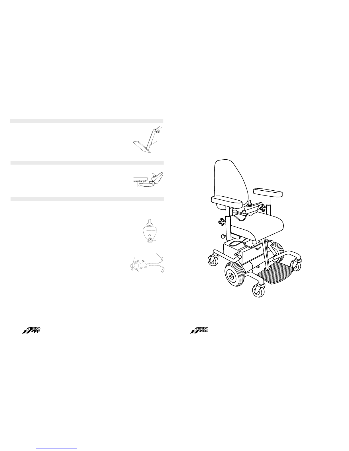
Adjustment of control box position
The control box can be adjusted for depth and sideways position. To adjust the depth, undo screw
(1) with a 5mm Allen key. Move the control arm to the required position (out of three possible)
and return the screw. The control box can also be moved sideways to either the inside or the outside
of the armrest. The control arm is jointed at two points. This allows the control box to be moved
horizontally and laterally without the use of tools. Push the control box into the desired position
and it locks into position itself. The control box can be placed on either side of the chair. 1
5
4
Box 1074, 181 22 Lidingö Telefon 08-555 143 00 Fax 08-555 143 99 E-post [email protected]
Export Office: Nobelweg 22, 3899 BN Zeewolde, The Netherlands, E-mail:[email protected]
www.mercado-medic.nl Tel: +31-(0)-36 521 99 95 Fax +31-(0)-36 521 99 90
INSTRUCTIONS
for USE and CARE
REAL 6100
Foot-plate/leg position
The foot-plate can be adjusted for height and angle. To adjust the height of the foo-tplate:
loosen screw (1). Adjust the foot-plate to the required height and tighten the screw. NB: ensure
that the screw enters one of the inner tube’s countersunk depressions. The angle of the foot-
plate is adjusted using screw (3) with a 5mm Allen key. To lower, turn the screw clockwise; to
raise, turn the screw anti-clockwise. The leg position can be adjusted to four positions. Loosen
and remove screw (2) with a 5mm Allen key. Set the required angle, return the screw into the
relevant hole and tighten.
2
1
3
Mercado 0604
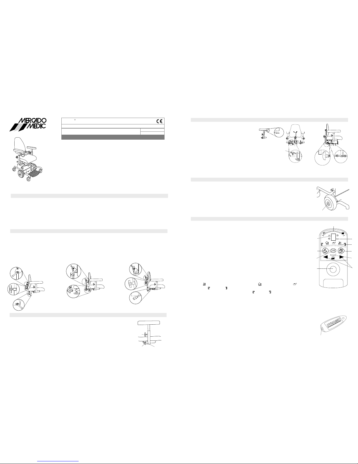
Control panel, manoeuvring the chair
Brake release
Disengaging the brake enables the chair to be moved manually. Turn the manoeuvre plate (1)
on both wheels a quarter turn anti-clockwise to disengage the brakes. If it is difficult to turn the
manoeuvre plate, try moving the chair backwards and forwards a little. To re-engage the brakes,
turn the plate (1) on both wheels a quarter turn clockwise and roll the chair carefully until the
brakes are engaged with an audible "click". NB: On no account must the main switch be on
when the brakes are disengaged. The brakes must never be engaged using the motor. The chair
must never be transported with the brakes disengaged. 1
Manoeuvring Driving
Turn on power switch (1). Check battery level (4). The battery level should not be down in the
red area. (see “charging”)
Driving: Check that the function display (3) shows number 2 (normal speed) or 1 (low speed). If
not, press function button (2) until one of the numbers is shown. Push joystick (5) straight ahead
for forward motion and diagonally forward left/right to turn. The chair can be spun around by
pushing the joystick (5) straight left/right. To back up, pull the joystick (5) back.
Manoeuvring Seating Unit:
For raising/lowering the seating unit or adjusting the electric seating angle/back angle or leg
support angle. Press option button (6). The electrical functions that are mounted on the chair
light up on the option display (7); the active electrical function blinks. Push joystick right/left
to switch between symbols on the option display and forward/backwards for manoeuvring the
various options.
(Symbol ) steers raising/lowering chair, (Symbol ) seating angle, (Symbol ) back angle
and (Symbol ) (Symbol ) for left/right leg support angle. The two leg support angles can be
manoeuvred simultaneously when both (Symbol ) (Symbol ) for left/right leg support angling
blink at the same time. When the chair’s electrical function is not used for five minutes, it shuts
off automatically in order to save battery capacity.
In order to start the electronics, press power switch (1) or touch the joystick (5). The time interval
for turning off is adjustable.
Signal horn: Press button (8).
Locking function: Use the magnetic key (9) in order to lock the electronics. The electronics must
be turned on with the power switch (1) when locking/unlocking. The magnetic key (9) is held
against the key symbol (10) for locking/unlocking. When locking, the manoeuvre panel turns off
completely, and the key symbol light blinks red; in order to unlock, the power switch (1) must be
turned on. When the chair is locked (and turned on), the red key symbol (10) lamp blinks; re-do
the procedure with the magnetic key (9).
The buttons (11) have not been programmed for any function.
9
Seat angle adjustment
Handle control
Gas spring
2
3
4
1
4
There are three alternative designs for adjusting
the angle of the seat: manual, gas spring and
handle control. Manual adjustment is done by
loosening the knob (1) beneath the seat. Adjust
to the position required and then lock the knob.
Please note! This knob should always be locked
when the chair is in use. The control for the gas
spring is situated at the back left-hand edge of
the seat (2) and is manoeuvred by pushing the
lever forward carefully. The controls may also be
placed under one of the armrests (3). The handle
device is manoeuvred using the handle (4).
REAL 6100
R
The REAL chair combines exchangeable components, accessories and func-
tions, with adjustability to your individual requirements. The chair is only to be
used by the person and for the purpose intended. The chair is designed for
indoor use only and should not be exposed to water, other liquids or chemicals.
It should not be exposed to high temperatures or long periods of intensive
sunlight or other radiation. The chair shall not be fitted with accessories or com-
ponents other than those approved by Mercado Medic AB. Repairs and other
technical measures may only be carried out by personnel authorised by Mer-
cado Medic AB. Please read the instructions carefully before using the chair.
INSTRUCTIONS for USE and CARE
Armrests
Articleno: 801974
April 2006
The armrests can be adjusted for height and width and can be folded back. The height is adjusted
with knob (1). To lower the armrest, unscrew the knob. To raise, life the armrest to the required
height and then lock in place with the knob. The width is adjusted using knob (2). Loosen
the knob, adjust and lock. Use knob (3) to fold the armrests back. Pull out and fold back. The
mechanism locks into position automatically when the armrests are folded back into an upright
position. It is possible to override the automatic locking by turning knob (3) a quarter turn.
Electrically powered wheelchair for indoor use for people with reduced functionality in the neck/back, in the legs and arms
1
23
Back rest
There are three types of back mechanisms: Standard, Medic and Comfort. The backrest is available in both a low
and a high design (all the chairs illustrated show the high backrest design). All back mechanisms have separate
adjustment controls for height (1) and angle (2). Loosen the knob, adjust to the desired height/angle and then lock
the knob. On the Comfort model with a gas spring device, push the lever forward to change the angle. On the
Medic model the depth can be adjusted by using the knob (3). In the high position the angle of the backrest itself
can be adjusted by using the knob. (4).
1
3
2
4
4
4
2
1
2
Standard Comfort
Medic
1
2
11
8
6
7
10
4
5
1
2
3
Importan t information
REAL 6100 belongs to class A and is only to be used indoors
Max user weight: 130 kg.
REAL 6100 is tried and approves according to the EMC-directive.
Cell phones do not compromise the REAL 6100 driving quality.
REAL 6100 can influence electromagnetic fields.
2
2
2
2
2
2
2
Other Mercado Medic Mobility Aid manuals


Popular Mobility Aid manuals by other brands


Jenile
Jenile Pack Hotel instruction manual

Direct Healthcare Group
Direct Healthcare Group SystemRoMedic BureDouble 2.0 Instructions for use

Invacare
Invacare IVC Heavy Duty Shower Chair 9780 Installation & operating instructions

Ki Mobility
Ki Mobility Little Wave Tyke User instruction manual & warranty

Krabat
Krabat Sheriff S1 user manual

aidapt
aidapt VM990BLK Usage and maintenance instructions


