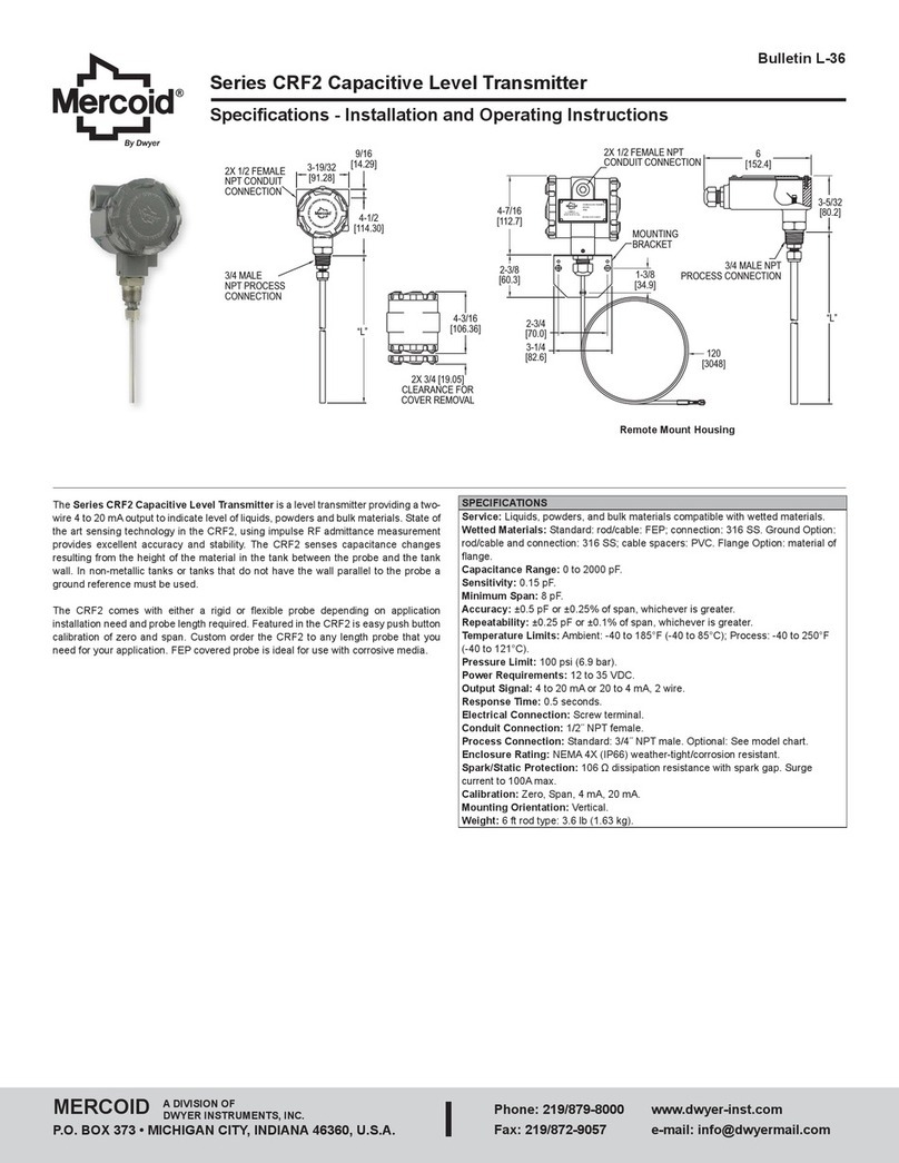
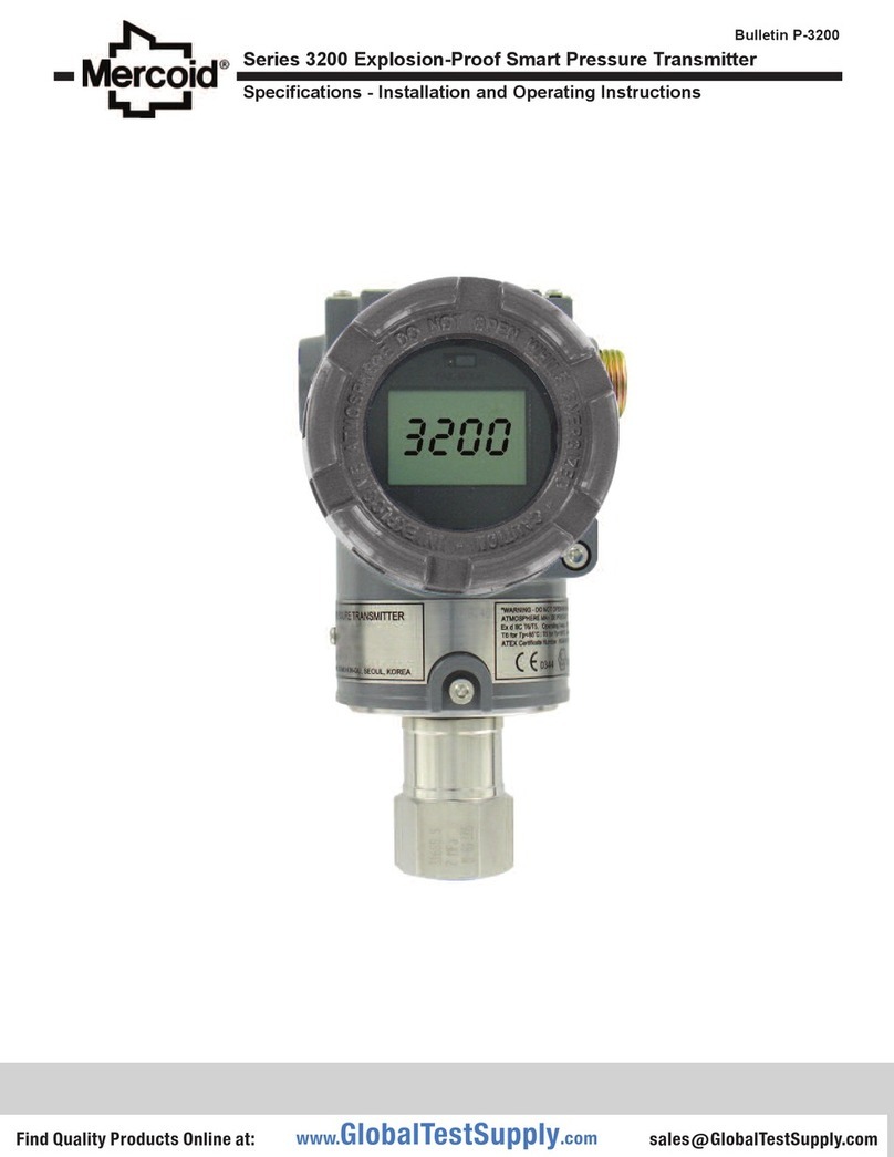
Mercoid 3100 User manual

Series 3100 Explosion-Proof Differential Pressure Transmitter
Specications - Installation and Operating Instructions
Bulletin P-3100
DWYER INSTRUMENTS, LLC
P.O. BOX 373 • MICHIGAN CITY, INDIANA 46360, U.S.A.
Phone: 219-879-8000
Fax: 219-872-9057
www.dwyer-inst.com
e-mail: [email protected]
Table of Contents
Chapter 1. Introduction
1.1 Using This Manual
1.2 Overview of Transmitter
1.3 Software Compatibility
Chapter 2. Handling Cautions
2.1 UnpackingTransmittersandSpecicationsCheck
2.2 ModelsandSpecicationsCheck
2.3 Storage
2.4 Selecting Installation Locations
2.5 Calibration after Installation
2.6 Pressure Connections
2.7 WaterproongCableConduitConnections
2.8 Restrictions on Use of Radio Transceiver
2.9 Installation Resistance Test and Dielectric Strength Test
2.10 Explosion-Proof Transmitters
2.11 EMC Conformity Standards
Chapter 3. Transmitter Functions
3.1 Overview
3.2 Safety Messages
3.3 Warning
3.4 Fail Mode Alarm
3.5 EEProm-Write Enable/Disable Mode Jumper
3.6 CongurationofAlarmandSecurityJumperProcedures
3.7 CongurationofZeroandSpanProcedures
3.8 Commissioning on the Bench with HHT
Chapter 4. Installation
4.1 Overview
4.2 Safety Messages
4.3 Warning
4.4 Commissioning on the Bench with Hand-Held Terminal
4.5 General Considerations
4.6 Electrical Considerations (Power Supply)
4.7 Wiring
4.8 Mechanical Considerations
4.9 Environmental Considerations
Chapter 5. On-line Operation
5.1 Overview
5.2 Safety Messages
5.3 CongurationDataReview
5.4 CongurationVerication
5.5 Basic Setup
5.6 Detailed Setup
5.7 CongurationVariablesSetup
5.8 Diagnostics and Services
5.9 Calibration
Chapter 6. Maintenance
6.1 Overview
6.2 Safety Messages
6.3 Hardware Diagnostics
6.4 Hardware Maintenance
Appendix I
3100 Smart Pressure Transmitter LCD Display Code

Step Job Job Details Instrument
1
2
3
4
5
6
7
8
9
10
11
Unpacking
Model and
Specications
Storage
Calibration
Installation
Locations
Mechanical
Considerations
Electrical
Considerations
Mounting and
Installation
Calibration on
Spot
Pressure
Operation
• Unpack transmitter packing
• Make sure the transmitter nameplate
matches the model number on the P.O.
• In a dry, non-vibration and non-impact
area
• Ambient temperature around 77°F
(25°C) and 65% relative humidity
•CongurationoftheRange,Zero/
Span, Unit, Tag, Dampening Time,
Transfer Function, DA Trim and other
parameters
• Where ambient temperature are
constant
• Exposure to chemical corrosion, etc.
• Where shock and vibration are minimal
• Wheretheareaclassicationdoesnot
exceed the explosion-proof rating
• Where maintenance is easy
• Where the transmitter can be handled
easily
• Be cautious of process connections
leaking
• 24VDC(PowerSupplyis11.9–45
VDC)
• For HART®communication, resistance
on transmitter terminal loop should be
between250–550Ωs
• When mounting the transmitter, an
appropriate bracket should be used
• The transmitter should be mounted
securely to prevent swing
• SensorZeroTrimshouldbedoneten
seconds after differential pressure
stabilizes
• MakesurethatPVvalueiszeroand
current is 4 mA
• Do not apply a regulated differential
pressure and line pressure
• Close the equalizing valve on the 3
valve manifold and then open the
valve on high and low side slowly and
simultaneously
• Make sure the transmitter operates
properly
• HHT
• Pressure
Source
• Galvanometer
• (Engineering)
• (Engineering)
• (Engineering)
• (Mounting and
Installation)
• HHTorZero/
Span button
• (Applying
pressure)
• Eye or HHT
Chapter 1 Introduction
The 3100 Smart Pressure Transmitter is calibrated at the factory before shipping. To
ensurecorrectandefcientuseoftheinstrument,pleasereadthemanualthoroughly
and fully understand how to operate the instrument before operation.
1. The contents of this manual are subject to change without prior notice.
2. All rights are reserved. No part of this manual may be reproduced in any form
without Dwyer Instruments, LLC written permission.
3. If any question arises, errors are found or if any information is missing from this
manual, please inform Dwyer Instruments, LLC
4. Thespecicationscoveredbythismanualarelimitedtostandardtransmittersand
do not cover custom-made instrument.
5. Pleasenotethatchangesinthespecications,construction,orcomponentparts
oftheinstrument maynotimmediatelybe reectedinthismanualatthetimeof
change,providedthatpostponementofrevisionswillnotcausedifcultytotheuser
from a functional or performance standpoint.
1.1 Using This Manual
The operating manual provides information on installing, operating, and maintaining
the Mercoid®Model 3100 Smart Pressure Transmitter. The Chapters are organized
as follows.
Chapter 2 Handling Cautions
Chapter 2 provides instructions on commissioning and operating the Model 3100
Smart Pressure Transmitters. Informations on software functions, conguration
parameters, and on-line variables are also included.
Chapter 3 Transmitter Functions
Chapter 3 contains suggestions on handling the Model 3100 Smart Pressure
Transmitter.
Chapter 4 Installation
Chapter 4 contains mechanical, environment consideration and electrical installation
instructions for the Model 3100 Smart Pressure Transmitter.
Chapter 5 On-line Operation
Chapter 5 describes how to congure the parameters of the Model 3100 Smart
Pressure Transmitter. See the following list for the details.
1. Regulations for circuit’s Input/Output characteristics; Sensor or Output Trim
2. Changing the output characteristic; Range Conguration, Output Type,
Dampening, Unit
3. Changing the general data; Tag No., Date, Message etc.
Chapter 6 Maintenance
Chapter 6 contains hardware diagnostics, troubleshooting and maintenance task.
1.2 Overview of Transmitter
The Mercoid®Smart Pressure Transmitter is a microprocessor based pressure
transmitter with a capacitance sensor optimized for draft measurement. The Model
3100 has a true draft analog range from 0 to 20 mA. This transmitter is explosion-
proof, high precision accuracy, reliability and has digital communication for remote
communication system.
The Model 3100 is enabled with HART®communication with Host, HHT (HART®
Communicator) or PC Congurator. The transmitter’s various variables in host are
abletobechanged,conguredandcalibratedbyusers.TheHART®Communication
betweenDCpowersupplyandtransmitterrequiresa250~550Ωresistance.
1.3 Software Compatibility
The Mercoid®Smart Pressure Transmitter’s software is implemented at the factory.
ThefollowingfunctionscanbeconguredusingaHHT(Hart®Communicator).
Function
Function Supports
ZERO/SPAN Button PC/PDA HART HHT
Rev.58
ZERO/SPAN
ZEROTRIM
ZEROAdj
Units set
Range set
Dampening set
LCD decimal set
•
•
•
•
•
•
•
•
•
•
•
•
•
•
•
•
•
•
•
•
∆
• : Supported
∆: Supported but update required
Chapter 2 Handling Cautions
This chapter consists of cautions for transmitter handling, storage, installation,
insulation and explosion structure, etc.
2.1 Unpacking Transmitters
When moving the transmitter to the installation site, keep it in the original packaging.
Unpack the transmitter at the installation site to avoid damage on the way.
2.2 Model and Specications Check
Themodelnumberandspecicationsareindicatedonthenameplate.Pleasecheck
thespecicationandmodelnumber.
2.3 Storage
The following precautions must be observed when storing the instrument, especially
for a long period of time.
1. Select a storage area that meets the following conditions:
• is not exposed to rain or water.
• minimal vibration and shock.
• stored at normal temperature and humidity (approx. 77°F (25°C), 65% RH).
The ambient temperature and relative humidity ratings are:
Ambient Temperature: -40 to 185°F (-40 to 85°C)
(without LCD module)
-22 to 176°F (-30 to 80°C)
(with LCD module)
General Use: -4 to 140°F (-20 to 60°C)
Relative Humidity: 5% ~ 98% RH at 104°F (40°C)
2. When storing the transmitter, repack it the way it was delivered from the factory.
3. If storing a used transmitter, thoroughly clean the diaphragm surfaces, so that
no media remains. Make sure the transmitter assemblies are securely mounted
before storing.

2.4 Selecting Installation Locations
The transmitter is designed to withstand severe environmental conditions. However,
to ensure stable and accurate operation, the following precautions must be observed
when selecting an installation location.
1. Ambient Temperature
Avoidlocationssubjecttowidetemperaturevariationsorasignicanttemperature
gradient. If the location is exposed to radiant heat from plant equipment, provide
adequate insulation or ventilation.
2. Ambient Atmosphere
Avoid installing the transmitter in a corrosive atmosphere. If the transmitter must
be installed in a corrosive atmosphere, there must be adequate ventilation.
Precautions must be put into place to prevent intrusion or stagnation of rainwater
in conduits.
3. ShockandVibration
Select an installation site with minimum shock and vibration (although the
transmitter is designed to be relatively resistant to shock and vibration).
4. Installation of Explosion-Proof Transmitters
Explosion-Proof transmitters can be installed in hazardous areas according to the
gastypesforwhichtheyarecertied.
5. Select a place where the transmitter can be maintenanced easily.
2.5 Calibration after Installation
1. SensorZeroTrimshouldbedoneaftertransmitterisinstalled,becausethezero
pointisnotconguredformountingstatus.
2. When calibrating the Sensor Zero Trim apply a pressure for zero in advance,
Sensor Zero Trim the sensor when the pressure is sufciently stabilized (after
approximately 10 seconds).
3. There are two ways to pressure zero. One way is to apply zero differential pressure
(making pressure the same on both the high and low side). The other is to close
High and Low side of a 3 valve manifold and open the equalizing valve.
4. Sensor Zero Trimming can also be done with the Zero/Span button or a HHT
(HART®Communicator),PCorPDAcongurator.
5. RefertoOn-lineOperationforconguringotherparameters.
2.6 Pressure Connections
The following precautions must be observed in order to safely operate the transmitter
under pressure.
1. Neverapplyapressurehigherthanthespeciedmaximumworkingpressure.
2. Conrmtheoptionpressureoftransmitter.Itisnecessarytousestandardizedand
quality-approved parts.
3. There should be isolation valves in case of leakage.
2.7 Waterproong Cable Conduit Connections
Apply a non-hardening sealant (silicone or tape, etc.) to the threads to waterproof the
transmitter cable conduit connections.
2.8 Restrictions on Use of Radio Transceivers
2.9 Installation Resistance Test and Dielectric Strength Test
Since the transmitter has undergone insulation resistance and dielectric strength tests
at the factory, normally these tests are not required. However, if required, observe the
following precautions in the test procedures.
1. Do not perform such tests more frequently than necessary. Even test voltages,
that do not cause visible damage to the insulation, may degrade the insulation and
reduce safety margins.
2. Neverapplyavoltageexceeding500VDCfortheinsulationresistancetest,ora
voltageexceeding500VACforthedielectricstrengthtest.
3. Before conducting these tests, disconnect all signal lines from the transmitter
terminals. Perform the tests in the following procedures.
Insulation Resistance test
1. Short-circuit the + and - SUPPLY terminals in the terminal box.
2. Turn OFF the insulation tester. Then connect the insulation tester plus (+)
lead-wire to the shorted SUPPLY terminals and the minus (-) lead wire to the
grounding terminal.
3. Turn ON the insulation tester power and measure the insulation resistance. The
voltage should be applied briey to verify that insulation resistance is at least
20MΩ.
4. After completing the test and being very careful not to touch exposed conductors.
Disconnect the insulation tester and connect a 100kW resistor between the
grounding terminal and the shortcircuiting SUPPLY terminals. Leave this resistor
connected at least three seconds to discharge any static potential. Do not touch the
terminal while it is discharging.
Dielectric Strength Test
1. Short-circuit the + and - SUPPLY terminals in the terminal box.
2. Turn off the dielectric strength tester. Then connect the tester between the shorted
SUPPLY terminal and the grounding terminal. Be sure to connect the grounding
lead of the dielectric strength tester to the ground terminal.
3. Set the current limit on the dielectric strength tester to 10 mA, then turn on the
powerandgraduallyincreasethetestervoltagefrom‘0’tothespeciedvoltage.
4. Whenthespeciedvoltageisreached,holditforoneminute.
5. After completing this test, slowly decrease the voltage to avoid any voltage surges.
2.10 Explosion-Proof Rating
2-10-1. FM Certication
HAZARDOUSLOCATIONELECTRICALEQUIPMENT
Equipment Rating: Explosion-Proof for use in Class I, Division 1, Groups A, B, C
and D;
Dust- Ignition-Proof for Class II/III, Division 1, Groups E, F and G;
Nonincensive for use in Class I, Division 2, Groups A, B, C and D;
Suitable for use in Class II, Division 2, Groups E, F and G; and Suitable for Class
III, Division 1;
Hazardous(classied)location,indoorandoutdoor(NEMAType4X/IP67).
1. SupplyVoltage:42VDC max
2. Output Signal: 4-20 mA + HART
1. All wiring shall comply with local installation requirement.
2. The cableglands and blanking elements shallbe of a certied ameproof type,
suitable for the condition of use and correctly installed. Also those devices should
be endured at the 130°C.
3. Housing Ground must be followed to “local electrical codes”.The most efcient
ground procedure is to connect directly to the earth as least impedance.
1. How to Housing Ground:
A. Internal Ground Connection:
Internal ground connection screw is located in terminal in housing; the
screwcanbeidentiedasgroundsign.
B. External Ground Assembly:
Thisislocatedintherightsideofhousingandidentiedasgroundsign.
(Grounding with a cable lug)
2. When use tubing, stopping boxes must be connected with the wall of housing
directly.
3. Tubing is installed a minimum of 5 threads.
4. Sensor is to be threaded a minimum of 7 threads and prevented from turing by
tightening the housing rotation set screw.
5. Do not disassemble ameproof Joints but in an unavoidable case to
disassemble it or need the specication of ameproof Joints, contact the
manufacturer before doing.
1. Take care not to generate mechanical spark when access to the instrument and
peripheral devices in hazardous location.
The instrument modication or parts replacement by other than authorized
representative of Dwyer/Mercoid is prohobited and will void explosion-proof/
ameproof.
Instrument installed in the process under pressure. Never loosen
ortightenasitmaycausedangerousspoutingofprocessuid.If
theprocessuidistoxicorotherwiseharmful,takeappropriatecaretoavoidcontact
or inhalation of vapors even after disconnecting the instrument from process line for
maintenance.
CAUTION
Although the transmitter has been designed to resist high
frequency electrical noise, if a radio transceiver is used near the
transmitters external wiring, the transmitter may be affected by high frequency noise
pickup. To test for such effects, bring the transceiver in slowly from a distance of
several feet from the transmitter, and observe the measurement loop for noise affects.
Always use the transceiver outside the area affected by noise.
WARNING
Electrical Data
NOTICE
Electrical Connection : 2 x 1/2-14 NPT Female
NOTICE
Installation
NOTICE
Operation
NOTICE
DONOTOPENWHENANEXPLOSIVEATMOSPHEREMAYBE
PRESENT.
WARNING
Maintenance and Repair
NOTICE

2.11 EMC Conformity Standards
EMI (Emission): EN55011
EMS (Immunity): EN50082-2
Dwyer Instruments, LLC recommends customer use metal conduit wiring or twisted
pair shield cable for signal wiring to conform with EMC regulation, when installing the
Mercoid®3100 transmitters.
Chapter 3 Transmitter Functions
3.1 Overview
This Chapter contains information on operating the Model 3100. Tasks that should be
performed on the bench prior to installation are explained in this chapter.
3.2 Safety Messages
Procedures and instructions in this chapter may require special precautions to ensure
the safety of the personnel performing the operations. Potential safety issues are
indicated by a warning symbol ( ). Refer to the following safety messages before
performing an operation preceded by this symbol.
3.3 Warning
3.4 Fail Mode Alarm
Mercoid®Smart Pressure Transmitter automatically and continuously performs self-
diagnostic test. If the self-diagnostic test detects a failure, the transmitter drives the
output outside of the normal operation values. The transmitter will drive its output low
(down) or high (up) based on the position of the failure mode alarm jumper. See Table
3.1 for output values.
Fail Safe mode can be set via Jumper switches provided on the LCD module or the
main CPU module. The jumper switch for an indicating transmitter, located on the LCD
module,canbesettotheright(faildowni.e.≤3.75mA)orleft(failupi.e.≥21.75mA).
For non-indicating transmitters the jumper switch is located on the main CPU module,
itcanbesetup(failup to ≥ 21.75mA)ordown(faildownto≤3.75mA). Refer to
Figure 3-1 for detailed summary of jumper settings for both CPU and LCD modules.
Table 3.1 Standard alarm and saturation values
1. WR_EN (EEPROM Write Enable)
DOWN : ENABLE
UP : DISABLE
2. Fail Mode(Alarm)
DOWN : LOW
UP : HIGH
3-5 EEProm-Write Enable / Disable Mode Switch
EEPROM (Electrically Erasable Programmable ROM), included on the CPU module,
is used by the transmitter to save/restore conguration variables. To protect the
transmitter from any unauthorized changes, a hardware lockout feature can be
implemented by using the Write-Protect mode jumper switch provided on the main
CPU Module. If the jumper switch is connected to DIS, this disables writing/changing
of any data saved in the EEPROM. On the other hand, if the jumper switch is set to
“EN”, changes can be made to the conguration data stored in the EEPROM. The
factory default setting is “EN” (Enable) for all transmitters. The location of the Wire
Protect Jumper Switch can be seen in Figure 3-3.
The 3100 has two security settings.
1. SecurityJumper:thetransmittercongurationparametersareprotected.
2. PhysicallyremovingZeroandSpanMagneticButtons:youareunabletoregulate
zero and span locally.
3.5.1 Security Jumper (EEPROM Write Protect)
Preventsthetransmitter’sconguredparametersfrombeingchanged.
3.5.2 Zero and Span Buttons
ByremovingtheMagneticButtons,youcan’tcongurethetransmitterusingtheZero
and Span locally.
3.6 Conguration of Alarm and Security Jumper Procedures Changing jumper
position.
1. If the transmitter is installed, cutoff power.
2. Open the front cover. If the transmitter is powered, don’t open the cover.
3. Move the jumper to the preferred position.
4. Close the front housing covers. You must fully engage the cover to meet explosion-
proof requirements.
Explosion can result in death or serious injury:
Do not remove the transmitter covers in explosion environments
when the circuit is powered. Transmitter covers must be fully engaged to meet
explosion-proof requirements.
DANGER
Electrical shock can result in serious injury:
Onlyqualiedpersonnelcaninstallthetransmitter.
WARNING
Level 4~20 mA Saturation 4~20 mA Alarm
Low/Down
High/Up
3.9 mA
20.8 mA
≤3.75mA
≥21.75mA
Electrical shock can result in serious injury:
Avoid contact with the leads and terminals. High voltage, that may
be present, on leads can cause electrical shock.
WARNING
OH
12
UP
DOWN
Fail Safe Mode Selection (LCD & CPU Module)
Select Fail
Mode
Both LCD Module and
CPU Module
Only CPU
Module
CPU Module
Down
Down
Up
LCD Module
D
U
U or D
LCD Module
D
U
U
Fail Down
Fail Up
Figure 3-2: Fail mode selection jumper switch for LCD module
Figure 3-1: Fail mode and EEPROM-write selection jumper switch
Fail Mode for LCD Module Selection Jumper Switch
UOOO OOOD OOOD
(If Down) FAIL MODE (If Up)
Figure 3-3: CPU module fail mode, EEPROM-write selection jumper switch
Fail mode select
jumper switch
CPU module jumper switch
1) Fail mode selection

3.7 Conguration of Zero and Span Procedures
The ZERO and SPAN Buttons are under the transmitter’s nameplate. The ZERO,
SPAN, ZERO TRIM, ZEROADJ, Units, Range, Dampening, LCD and decimal set
functionsarecongurableusingtheZERO/SPANbuttons.
Zero/Span Conguration Process
Remove both name plate screws on the upper part of transmitter. Remove top name
platetoaccesstheZeroandSpanButtons(followingFigure 3-4).
1. ZeroCongurations
SetthecurrentprocessvalueforLowerRangeValue(4mA).Applyzeropressure
for10secondsandpushtheZeroButtonfor5seconds.TheLCDshoulddisplay
“Zero”. Push the Zero button for 3 seconds, after 1 second the LCD should
display“-ZE-”.Thismessagemeansthezerocongurationisnished.Ifthezero
congurationfailed,theLCDwilldisplay“SPEr”or“SEtE”,tryrepeatingthezero
congurationsteps.
2. SpanCongurations
Apply the desired pressure for 10 seconds and push the Span Button for 5
seconds. The LCD should display “Span”. Push the Span button for 3 seconds,
after 1 second the LCD should display “-SP-”. This message means that the span
congurationisnished.IfthespancongurationfailedtheLCDwilldisplay“SPEr”
or“SEtE”,tryrepeatingthespancongurationsteps.
• Please refer to Appendix 1 for the button error and LCD display message. The
otherfunctionssupportedbytheZERO/SPANButtonsarebelow.
4. How to select a numerical value
A. Functionsusenumericalvalues:12ZeroAdjustment,22ChangeUpperRange
Value,23ChangeLowerRangeValue,24DampeningSecond
B. How to select numerical value: First, select an increasing rate (10n), then
change each decimal value to increase or decrease as wanted. For example,
select 3810 : Select increasing rate 1000 -> Increase 3 times -> Select
increasing rate 100 -> Increase 8 times -> Select increasing rate as 10 ->
Increase 1 time
C. To select the increase / decrease steps: SelInc message will be displayed
onthebottomoftheLCD.SelectparameterandpresstheZerobutton:The
decimalvaluewillbechangedwhentheZerobuttonispressed.Afterset,press
the span button to execute the parameter.
D. TosettherequiredvaluesusingZero/Spanbuttons:VALUEmessagewillbe
displayed on the bottom of the LCD.
1. PresstheZerobutton,themenuwillincrease1item.
2. Press the Span button, the menu will decrease 1 item.
3. Aftersetting,savetheparameterbypressingtheZero+Spanbuttons.
E. Tosetthenalvalue,repeatCandD.
F. After setting the nal parameter, exit the menu by pressing the Zero+Span
buttons.
5. Exercises for each function
• ZEROTRIM
1. AccessthemenubypressingtheZero+Spanbuttons.
2. Move to the sub directory using the Span button until the 1 TRIM message
appears on the display.
3. ChangetheZeroTrimFunctionbyusingtheSpanbuttonuntilthe11Z-TRIM
message appears on the display.
• ZEROADJUSTMENT:ChangethePVvalueto14
1. ExitthemenubypressingtheZero+Spanbutton.
2. Moving through the sub directory using the Span button until 1 TRIM message
appears.
3. Moving through the sub directory using the Zero button until 11 Z-TRIM
message appears.
4. AccesstheZeroAdjustmentfunctionbypressingtheSpanbuttonuntilthe12
Z-ADJmessagesappears.
5. WhentheSelIncmessageappears,presstheZero button repetitively until
the 10.0 message appears on the LCD. Set the value by pressing the Span
button.
6. WhenVALUEmessageappears,changetheLCDvalueto10.0andpressthe
Zerobutton,thenpresstheZero+Spanbuttons.
7. When Sellnc message appears, change the LCD value to 1.0 and press
the Zero button, then set the value and press the Span button. Press the
Zero+SpanbuttonsaftertheLCDvaluechangesto14.0.
8. Tosavethesettings,presstheZero+SpanbuttonsuntiltheSelIncmessage
appears.
• CHANGE UNITS
1. AccessthemenubypressingtheZero+Spanbuttons.
2. MovingtonextmenubypressingtheZerobuttonuntilthe1TRIMmessage
appears.
3. Moving through the sub directory press the Span button until the 2 SETUP
message appears.
4. Press the Span button to access 21 UNIT, press Span again to access
Change Unit.
5. Save the values by pressing the Span button when the desired value is
displayed on the LCD.
• CHANGEUPPERRANGEVALUE
1. AccessthemenubypressingtheZero+Spanbuttons.
2. MovetothenextmenubypressingtheZerobuttonuntilthe1TRIMmessage
appears.
3. Press the Span button until the 2 SETUP message appears.
4. Press the Span button until the 21 Unit message appears.
5. PresstheZerobuttonuntilthe22U-RNGmessageappears.
6. PresstheSpanbuttonuntiltheZeroAdjustmentmessageappears.
• CHANGELOWERRANGEVALUE
1. AccessthemenubypressingtheZero+Spanbuttons.
2. MovethetonextmenubypressingtheZerobuttonuntilthe1TRIMmessage
appears.
3. Press the Span button until the 2 SETUP message appears.
4. Press the Span button until the 21 Unit message appears.
5. PresstheZerobuttonuntilthe22U-RNGmessageappears.
6. PresstheZerobuttonuntilthe23L-RNGmessageappears.
7. Press the Span button until the Change Lower Range Value message
appears.
PushZero ZeroCalibration
Push Span
{Menu}
1 Trim
2 Setup
3 LCD
11Z-Trim
12Z-Adi.
21 Unit
31 LCD-MD
32 Dec-PL
22 U-Rng.
23 L-Rng.
24 Damp
ZeroTrim
Zero
Adjust
Select
Eng. Unit
SetPV
-%-mA
rotation
Set Display
Resolution
Upper
Range
Lower
Range
Damping
Span Calibration
{ZeroorSpan}
Push
Both
S&Z
S = Span Button
Z=ZeroButton
Zero+Span
(previous or store)
< >
Smart transmitter quick push-button bench-calibration
[MenuTreeforZero+SpanButtonFunction]
1. Movingbetweenmenus:Zero
2. Enter or moving to sub menu: Span
3. Movingtotopmenu:Zero+Span
• Press the button for 3 seconds to execute each function. After 3 seconds press
theZero+Spanbuttons,theLCDdisplaywillchangefromMenutoTrim.Tosee
thenextmenu,presstheZerobuttonfor3seconds.UsetheZerobuttontomove
down the directory.
• Use the Span button to select the displayed menu. The same procedure will be
used for the sub menus.
30 seconds without any action, the button function will return to
normal operation.
CAUTION

• CHANGE LCD MODE (Cyclic or Fixed Display)
1. Enter programming menu by pushing both (ZERO+SPAN) button together
for 5 seconds. Release buttons when LCD displays Menu and display will
automaticallychangeto“1TRIM”conrmingaccessintoprogrammingmenu.
2. Push (ZERO) button when “1 TRIM” message appears on LCD. Release
button when display changes to “2 SETUP”.
3. Push(Zero)buttonandreleasewhendisplaychangesto“3LCD”.
4. To move into sub directory push (Span) button after “3 LCD” message
appears on display. Release button when 31 LCDMD message is displayed.
5. To enter this sub-menu, push (Span) button and release when display
changes to 311. Bottom line of display will show current Mode setting e.g.
NOR-RO,NOR-PVetc.
6. Push (Zero) button to cycle through available mode options and select
desired LCD rotation mode. Options are: NOR-RO (rotate all PV, %, mA),
NOR-PV(xedPV), NOR-% (xed %), NOR-mAxed, ENG-RO,ENG-PV,
ENG-% or ENG-mA
7. Push(Span)tosavechangesandEXITprogrammingmode.
• DECIMAL PLACE
1. AccessthemenubypressingtheZero+Spanbuttons.
2. MovetothenextmenubypressingtheZerobuttonuntilthe1TRIMmessage
appears.
3. Press the Span button until the 2 SETUP message appears.
4. Press the Span button until the 3 LCD message appears.
5. Press the Span button until the 31 DEC-PL message appears.
6. Press the Span button until the Decimal Place message appears, the decimal
place will appear on the second line of the LCD as follows.
Display Explanation Max. Value
AUTO
5-0
4-1
3-2
2-3
1-4
Target value will be displayed automatically
No decimal place
Display one decimal place
Display two decimal places
Display three decimal places
Display four decimal places
99999
99999
9999.9
999.99
99.999
9.9999
7. TherstlineontheLCDwilldisplay0.0.
8. The Decimal Place can be changed by pressing the Zero button. Save
the setting by pressing the Span button after the decimal place has been
selected.
9. ThesetvaluewilldisplaythePVvalueandEngineeringvalue.
10.TheLCDwilldisplayLCD_OVandthesavedUnitwhenthepressureisover
or under a set value.
Figure 3-4: Transmitter zero/span conguration buttons
3.8 Commissioning on the Bench with HHT
The 3100 Pressure Transmitter can be commissioned using an HHT before or after
installation.
Connect an HHT (HART®HANDHELD Communicator) across the COMM pins
for HART®communication. The TEST pin connections can be used for connecting a
multimeter to measure the output current directly from the transmitter. Since the 3100
isa2-wirelooppoweredtransmitter,itrequiresanexternallooppowersupply(11.9V
to45VDC)toenableHART®communication. Any HART®communication via HHT (or
PCbasedcongurator)requiresaminimum250~550(max)Ωloopresistance.
Figure 3-5: Connecting the transmitter to HHT
Chapter 4 Installation
4.1 Overview
The information in Chapter 4 explains installation.
4.2 Safety Messages
Procedures and instructions in this chapter may require special safety measures to
ensure the safety of the personnel performing the operation. Potential installation
safety issues are indicated by a safety alert symbol ( ). Refer to the following safety
messages before installing the 3100 pressure transmitter.
4.3 Warning
Explosion can result in death or serious injury: Do not remove
the transmitter covers in an explosion-proof environment when
the circuit is powered. Both transmitter covers must be fully engaged to meet the
explosion-proof requirements.
Electrical shock can result in death or serious injury: Avoid contact
with the leads and terminals.
DANGER
DANGER
Electrical shock can result in serious injury: Only qualied
personnel can wire the pressure transmitter.
WARNING
Process leaks can cause death or serious injury: Install and tighten
before applying pressure. If you don’t, it can cause process leaks.
WARNING
4.4 Commissioning on the Bench with Hand-Held Terminal
The 3100 Pressure Transmitter can be commissioned before and after installation.
CommissioningiseasierifthetransmitterisconguredonabenchwithanHHTbefore
installation.
4.5 General Considerations
The transmitter can be mounted near the process to minimize piping. Keep in mind
that easy access is required for personnel, eld calibration, and installation. Install
thetransmitterinanareawithminimalvibration,shock,andtemperatureuctuations.
4.6 Electrical Considerations (Power Supply)
The transmitter housing is composed of two parts. One side is electronics, and the
other side is terminal block. The terminal block side is the transmitter’s front side
and is labeled “Field Terminal” on the housing. The terminal block can be accessed
by removing the front cover. When wiring the power supply to the transmitter make
surethepositiveandnegativewiresareconnectedcorrectly.AHHTconguratorcan
be connected directly across the (COMM) pin terminal located just below the power
supply (PWR) terminal block connections.
Zero/span
buttons
LOCAL
TEST OR
REMOTE
INDICA
TOR
POWER SUPPLY
HHT
HART MODEM
(HART/RS232)
PC
CONFIGURATOR
POWER/SIGNAL CONNECTIONS
INDICATOR RECORDER
CONTROLLER DCS...ETC.
250-550 OHM
(24VDC)
1.HHT (HART COMMUNICATOR) OR PC CONFIGUATOR MAY BE CONNECTED AT
ANY TERMINAL PONT IN THE SIGNAL LOOP.
2.HART COMMUNICATION REQUIRES A LOOP RESISTENACE 250 AND 550 OHM
(24VDC).
3.TRANSMITTER OPERATES ON 11.9 TO 45.0 VDC TERMINAL VOLTAGE.
[APPLIED POWER]
*11.9 ~ 45.0 VDC FOR GENERAL OPERATION
*17.4 ~ 45.0 VDC FOR HART COMMUNICATION
CONTROL ROOMFIELD

4.6.1 Power Supply
The3100PressureTransmitterrequiresan11.9–45VDCpowersupply.A250~
550Ω(24VDC)loopresistanceisrecommendedforHART®communication. Loop
resistance is the sum of the resistance in the loop.
Max Loop Resistance [Ω] = (E-11.9) [VDC] / 0.022 [mA]
4.7 Wiring
4.7.1 Wiring Caution
1. Install the signal cables away from potential sources of electrical noise such as
transformers, electrical motors, etc.
2. Before wiring, remove electrical conduit cap.
3. All screwed connections on the housing must be sealed with waterproof sealant.
We recommend use of silicone based sealants to minimize post-hardening.
4. Avoid running DC signal and AC power cables in the same ducts/cable conduits to
avoid signal noise issues.
5. All explosion-proof transmitters must meet the wiring & installation requirements
speciedwithintheapplicableelectricalcodes.
4.7.2 Selecting the Wiring Materials
1. Use600VshieldedPVCwireorstandardwireofthesameclass(Toensureproper
communication use 24 AWG or larger wire, and do not exceed 5000 feet).
2. Use shielded wire in areas with electrical noise.
3. In areas with high or low ambient temperatures, use wire or cable that is rated for
the extreme temperatures.
4. If the wire or cable is going to be used in oil, solvent, toxic gas or liquid, make sure
it is rated accordingly.
5. Process wire or cable must not be soldered to the terminal lug. Spade connectors
are recommended to connect the process wires to the transmitter.
4.7.3 Connecting External Wires to Transmitter Terminal Box
1. Open the cover indicated “FIELD TERMINAL”. Do not open the cover if the
transmitter is located in an explosion-proof area and powered. Connect the power
supply to the terminal indicated “+PWR”(left terminal) and “-” in the central terminal.
Do not connect “+” power supply to “+” terminal “TEST”. It will damage the test
diode.
2. Seal and close the conduit connection to prevent humidity and explosion-proof
atmosphere from entering the housing.
3. Transmitter power is supplied by signal wire. Do not install near high voltage wires
or high voltage equipment.
4. Close the transmitter cover. To meet the explosion-proof ratings make sure the
covers are fully engaged. Note: Do not power the transmitter with high voltage
(AC). It can damage the transmitter.
5. Youmustconnecta250~550ΩResistorinCurrentLoop(betweenPowerSupply
and Transmitter) for HART®Communication. See Figure 4-2.
4.7.4 Wiring (Loop Conguration)
A. Loop Conguration
Mercoid®3100 Pressure Transmitters use a two-wire system for power, 4~20mA
analog signal transmission and HART®digital transmission. A DC Power Supply
is required for the transmitter loop. The transmitter and power supply should be
connected as shown below.
250~550 Ω
(24 VDC)
DCS OR
POWER SUPPLY
Figure 4-2: Wiring the 3100 pressure transmitter
Figure 4-3: Picture of transmitter wiring terminal
Explosion can result in death or serious injury: Do not remove the
transmitter covers in an explosion-proof environment when the
circuit is powered. Both transmitter covers must be fully engaged to meet explosion-
proof requirements.
DANGER
HAZARDOUS LOCATION
TRANSMITTER TERMINAL BOX NONHAZARDOUS LOCATION
OTHER DEVICES
(DCS,
RECORDER...)
POWER
SUPPLY
11.9~45VDC
Figure 4-1: Installation ow chart
Start
End
Do you satisfy spec?
Basic Setup
a) Unit setup
b) Range setup
c) Dampening setup
d) Transmitter function setup
Yes
Verify
a) Pressure support
Field Install
a) Jumper/switch setup
b) Transmitter takes up
c) Transmitter leads
d) Transmitter for Power Supply
No
Maintenance
Do you want
Galvanoometer
- +

4.7.5 Grounding
a. Grounding should satisfy KS requirements (grounding resistance should be 10
Ωorless).Groundingisrequiredforexplosion-proofapplicationsandtheground
resistancemustbebelow10Ωs.Note: In case of Built-in Lightening Protector,
GroundingshouldsatisfySpecialKSrequirements(groundingresistance,10Ω
or less).
b. There are ground terminals on the inside and outside of the transmitter. Either of
these terminals may be used.
c. Use600VinsulatedPVCwireforgrounding.
INTERNAL
GROUND
TERMINAL
EXTERNA
L
GROUND
TERMINAL
3100 Smart Pressure Transmitter
Internal and External Ground Terminal
4.7.6 Power Supply Voltage and Load Resistance
Whenconguringtheloop,makesurethattheexternalloadresistanceiswithinthe
range(seegurebelow).Thetransmittersupplyvoltageshouldbe:
• Standard: 11.9-45 VDC
• HART®Communication: 17.4-45 VDC
And maximum loop current is 24mA, Load resistance R:
R=(E-11.9)/0.022(E=PowerSupplyVoltage)
4.8 Mechanical Considerations
Figure 4-6 is a dimensional drawing for the 3100. Figure 4-7 shows how the A-630
angle bracket is mounted to a pipe.
Figure 4-6: Model 3100 outline dimension drawing
B. Wiring Installation
General-use (Figure 4-4a)
1. Use metallic conduit or waterproof cable glands for wiring.
a. Apply non-hardening sealant to the terminal box and the threads on the
exiblemetalconduitforwaterproong.
Figure 4-4a: Typical mounting using exible metal conduit
Explosion-proof
1. Explosion-proof metal conduit wiring (Figure 4-4b)
a. Asealttingmustbeinstalledneartheterminalboxport.
b. Apply a non-hardening sealant to the threads of the terminal connection box.
FLEXIBLE METAL
CONDUIT
WIRING METAL
CONDUIT
APPLY A NONHARDENING
SEALANT TO THE THREADS
FOR WATERPROOFING
TEE
DRAIN PLUG
Figure 4-4b: Typical wiring using explosion-proof conduit
NON-HAZARDOUS
AREA
HAZARDOUS
AREA
GAS SEALING
DEVICE
FLAMEPROOF
FLEXIBLE
METAL
CONDUIT
FLAMEPROOF
HEAVY-GAUGE
STEEL CONDUIT
TEE
DRAIN PLUG
APPLY A NONHARDENING
SEALANT TO THE
THREADS
OF THESE FITTINGS FOR
WATERPROOFING
SEAL FITTING
AFTER WIRING, IMPREGNATE
THEFITTING WITH A
COMPOUND TO SEAL TUBING
Figure 4-7: A-630 mounting bracket
R=(E-11.9)/0.022
HART COMMUNICATION
APPLICABLE RANGE
POWER SUPPLY VOLTAGE E(VDC)
11.9 17.4 25.1 42.0 45.
0
0
250
600
1500
EXTERNAL LOAD R(Ω)
2.875
[73 mm]
1.536
[39 mm]
4.055
[103 mm]
2.717
[69 mm]
4.411
[112 mm]
3.860
[98 mm]
REMOVAL
CLEARANCE
FOR
ALL COVERS
VERTICAL PIPE
MOUNTING
HORIZONTAL PIPE
MOUNTING
VERTICAL MOUNTING TYPE
2˝ PIPE MOUNTING BRACKET
MODEL: A-630

5.5.2 Set Output Units
Select from the following engineering units:
Volumetric Flow Unit:
CubicFeet/min, Gallons/min, Liters/min, ImperialGallons/min, CubicMeter/hr, Ft/s,
meters/s, Gallons/s, mGallons/day, Liters/s, mLiters/day, CubicFeet/s, CubicMeter/s,
CubicMeter/day, ImperialGallons/hr, ImperialGallons/day, NormalCubicMeter/hr,
NormalLiter/hr, StandardCubicFeet/min, CubicFeet/hr, CubicFeet/day, CubicMeters/
min, Barrels/s, Barrels/min, Barrels/hr, Barrels/day, Gallons/hr, ImperialGallons/s,
Liters/hr, Gallons/day
Mass Flow
Grams/s, Grams/min, Grams/hr, Kilograms/s, Kilograms/min, Kilograms/hr,
Kilograms/day, MetricTons/min, MetricTons/hr, MetricTons/day, Pounds/s, Pounds/
min, Pounds/hr, Pounds/day, ShortTons/min, ShortTons/hr, ShortTons/day,
LongTons/hr, LongTons/day
Pressure
kPa, mmH2O, InH2O, InHg, FtH2O, mmHg, psi, bar, mbar, g/cm^2, Kg/cm^2,
Pascals, MPa, torr, ATM
Miscellaneous
%
Time
Min, sec, hr, days
Mass
Grams, kilograms, metric tons, pounds, short tons, long tons, ounce
Volume
Gallons, liters, imperial gallons, cubic meters, barrels, bushels, cubic yards, cubic
feet, cubic inches, bbl liq, normal cubic meter, normal liter, standard cubic feet,
hectoliters
5.5.3 4-20mA Conguration
SettheZeroandSpanforthe4~20mAanalogoutput.
5.6 Detailed Setup
5.6.1 Set Fail Mode
When the sensor or microprocessor is not operating properly, the transmitter will
output 3.75mA or 21.75mA based on the Fail Mode setting.
5.6.2 Set Dampening Time
The Dampening Seconds value changes the response time of the transmitter to
smooth out variations caused by rapid process changes. Determine the appropriate
dampening setting based on the required response time, signal stability, and other
requirements of your system. The Dampening Seconds can be set from 0-60
seconds; the default dampening value is 1.0 second.
PRESSURE RELEASED
RESPONSE TIME =
TD + TC
TD TC
20 MA
9.89 MA
4 MA
TIME
63.2% OF TOTAL
STEP CHANGE
THE MEANING OF
DAMPENING TIME
IS TO REACH 63.2%
OF TARGET
4.8.1 Mounting
Avoid installing transmitters in environments with excessive vibration. If it cannot be
avoided it is highly recommended to provide adequate support when mounting.
4.8.2 Transmitter Access
When selecting the installation location, accessibility must be taken into consideration.
• Housing rotation: The housing can be rotated 90°.
• Wiring terminals: The cover and wiring terminals are easily accessible.
• LCD/Circuits: Install the transmitter in a location where it can be seen. For transmitters
without an LCD, the cover and jumpers are easily accessible.
4.9 Environmental Considerations
4.9.1 Ambient Temperature
The transmitter ambient temperature range is 4 to 180°F (-20 to 60°C). If the ambient
temperature is going to exceed the temperature range, precautions must be taken to
keep the temperature within the temperature limits.
4.9.2 Toxic and Moist Environments
The 3100 housing will protect the transmitter against moisture or toxic material. The
electronic circuit is separated from the terminals. The housing covers have O-rings
that seal the housing, but moisture can penetrate the housing through the conduit.
The transmitter should be mounted in a position to prevent moisture from entering
the housing through the conduit.
4.9.3 Installation in Hazardous Location
The transmitter is designed with an explosion-proof housing. Installation environment
must not exceed the explosion-proof rating.
Chapter 5 On-Line Operation
5.1 Overview
This chapter describes how to congure the 3100 Smart Pressure Transmitter.
Thetransmittercanbecongured inOn-LineorOff-Linemode. InOn-LineModea
compatibleHHTorPCcongurationdevicemustbeused.
5.2 Safety Messages
Foraddedoperatorsafetypleasepayspecicattentiontoproceduresoutlinedinthis
manual listed under the warning symbol ( ).
5.2.1 Warning
Explosion can result in death or serious injury: Do not remove
the transmitter covers in explosion-proof environments when the
circuit is powered. Both transmitter covers must be fully engaged to meet explosion-
proof requirements.
DANGER
Electrical shock can result in serious injury: When installing
transmitters in close proximity of high voltage sources (near
power lines) the transmitter leads can be subject to high voltages. Avoid contact with
the leads and terminals.
DANGER
5.2.2 Current to Passive Mode Conguration
Formulti-dropmodethecurrentoutputmustbeconguredaspassivemode.Please
disregard any other messages shown on HHT.
5.3 Conguration Data Review
Beforeoperatingthetransmittermakesurethecongurationdataonthenameplate
matches the application.
5.4 Conguration Verication
Before the transmitter is ready for service, the conguration must be checked to
conrmthesettingsareconguredfortheapplication.
5.4.1 Process Variable
There are two process variables in the 3100 Smart Pressure Transmitter. The
primaryvariableandtemperaturecompensatedSV(SecondVariable),thePVvalue
outputs the 4~20mA analog value.
5.5 Basic Setup
Thecorrelationvariablemustbeconguredbeforeoperatingthetransmitter.
5.5.1 Select Sensor Range
The pressure range must be selected when ordering the pressure transmitter.
5.7 Conguration of Information Variable
5.7.1 Set Tag
Tags are an easy way to classify transmitters in multi transmitter application. Tags
can use 8 words/numbers.
5.7.2 Set Messages
Whenusingseveraltransmitters,theusercandeneeachtransmitterbyusing32
words/numbers. This message is saved in EEPROM.

Symptom Potential Source Corrective Action
Transmitter does
not Communicate
with HART®
Communicator
• Loop Wiring • Checkfora250-550Ωs
resistance between the
power supply and HHT.
• Check for adequate voltage
to the transmitter (the
transmitter requires 11.9 ~
45 VDC).
• Check for intermittent
shorts, open circuits, and
multiple grounds.
High Output • Sensor Input Failure
• Loop Wiring
• Power Supply
• Electronics Module
• Connect HHT and enter
the transmitter test mode to
isolate a sensor failure.
• Check for dirty or defective
terminals, interconnecting
pins, or receptacles.
• Check the output voltage
of the power supply at the
transmitter terminals. It
should be 11.9-45 VDC.
• Connect HHT and enter
the transmitter test mode
to isolate module failure.
Check the sensor limits
to ensure the calibration
adjustments are within the
sensor range.
Erratic Output • Loop Wiring
• Electronics Module
• Check the output voltage
of the power supply at the
transmitter terminals. It
should be 11.9-45 VDC.
• Check for intermittent
shorts, open circuits, and
multiple grounds.
• Check for proper polarity at
the signal terminals.
• Connect HHT and enter
the transmitter test mode to
isolate an electronics mode
failure.
Low Output or No
Output
• Sensor Element
• Loop Wiring
• Electronics Module
• Connect HHT and enter
the transmitter test mode to
isolate a sensor failure.
• IsthePVoutofrange.
• Check for adequate voltage
to the transmitter (the
transmitter requires 11.9 ~
45 VDC).
• Check for intermittent
shorts, open circuits, and
multiple grounds.
• Check polarity of signal
terminal.
• Check the loop impedance.
• Connect HHT and check
the sensor limits to ensure
calibration adjustments are
within the sensor range.
6.4 Hardware Maintenance
The Mercoid®3100 Smart Transmitter has no moving parts and requires little
maintenance. If a transmitter fails, it must be returned to Dwyer Instruments, LLC for
inspection, repair, or replacement.
6.4.1 Test Terminals
The test terminals are marked TEST on the terminal block. The test and negative
terminals are connected to the power terminals; so long as the voltage across the
receptacles are below the diode threshold voltage, no current will pass through the
diode. To ensure that current isn’t leaking through the diode, test the reading with an
indicatingmeter.Thetestconnectionshouldnotexceed10Ωs.Aresistancevalueof
30Ωswillcauseanapproximate10percentofreadingerror.
6.3 Hardware Diagnostics
If there is a failure despite a diagnostic message on the HHT, Table 6.1 can help
troubleshoot the problem.
5.8 Diagnostics and Service
5.8.1 Loop Test
TheLoopTestveriestheoutputofthetransmitter,theintegrityoftheloop,andthe
operations of any recorders or similar devices installed in the loop. The following
procedures are required for a loop test.
• Connect a reference meter to the transmitter.
• Select the Loop Test on the HHT and operate the Loop Test.
• Select current output (4mA/20mA/etc.)
• If the readings match, then the transmitter and the loop are congured and
functioning properly. If the readings do not match, then you may have the current
meter attached to the wrong loop, there may be a fault in the wiring, the transmitter
may require an output trim, or the current meter may be malfunctioning.
5.9 Calibration
The scale is implemented by calibrating the transmitter. Trim function has several
calibration functions. Smart transmitters operate differently than analog transmitter. A
smart transmitter uses a microprocessor that contains information about the sensor’s
specic characteristics in response to pressure and temperature for calculating the
process variable. 4-20mA conguration sets the transmitter’s analog output to a
selected upper and lower range and can be done with or without an applied pressure.
4-20mA conguration does not change the factory characterization curve stored in
the microprocessor. Sensor trimming requires an accurate pressure input and adds
additional compensation that adjusts the factory characterization curve to optimize
transmitter performance over a specic pressure range. 4-20mA conguration
provides the ability to readjust the 4~20mA sensor inputs without an applied
pressure. Reranging does not change the factory or characterization curve stored in
the microprocessor. Sensor trimming requires an accurate pressure input and adds
additional compensation to the factory characterization curve to optimize transmitter
performanceoveraspecicpressurerange.Rerangeprovidesabilitytoreadjustthe
4~20 mA points sensor inputs.
5.9.1 Sensor Trim
The Sensor trim function adjusts the A/D signal conversion within the transmitter
sensor electronics and determines how it digitally interprets any pressure changes
applied to the sensor inputs. It is highly recommended to perform a sensor trim
whenrstcommissioning thetransmitteronsite.Therearethreewaystotrim the
sensor: Sensor zero trim, full trim and zero adjustment. Sensor zero trim is a one-
point adjustment typically used to compensate for the mounting position. Two point
trim is a full sensor trim, in which two accurate pressures are applied (equal to or
greater than the range values), and the output is linear. You should always adjust the
lowtrimvaluersttoestablishthecorrectoffset.
5.9.2 D/A (Digital to Analog) Trim
The D/A trim function makes minor adjustments to the analog (4-20mA) output
scaling from the transmitter. It is recommended to do a D/A trim on both hi (20mA) &
low (4mA) values for best results. This function corrects any minuscule offsets within
the D/A conversion of the transmitter.
Chapter 6 Maintenance
6.1 Overview
This chapter describes diagnostic and maintenance.
6.2 Safety Messages
When the transmitter is in operation, operators should follow all safety messages.
Potential safety issues are indicated by a safety alert symbol ( ). Refer to the following
safety messages before performing any operation proceeded by a ( ) symbol.
6.2.1 Warning
Explosion can result in death or serious injury: Do not remove
the transmitter covers in explosion-proof environments when the
circuit is powered. Both transmitter covers must be fully engaged to meet explosion-
proof requirements.
DANGER
Electrical shock can result in serious injury: When installing
transmitters in close proximity of high voltage sources (near
power lines) the transmitter leads can be subject to high voltages. Avoid contact with
the leads and terminals.
DANGER
Electrical shock can result in death or serious injury: Only
qualied personnel can congure and wire the 3100 Smart
Pressure Transmitter.
WARNING
Table 6.1 Troubleshooting

Appendix I
3100 SMART PRESSURE TRANSMITTER - LCD DISPLAY CODE
Message Description
ADJ-U
ADJ-L
ZERO
SPAN
BT-ERR
P-LOCK
ZT-ERR
-TR-
ZR-ERR
SP-ERR
-ZR-
-SP-
-ZA-
-DONE-
RNGOVR
LCD_OV
SCD-ER
F-RST
F-LOCK
F-FAIL
-FR-
A-RST
A-STOR
A-FAIL
-AC-
S-FL
S-OP
AEP-RF
TS-FL
AEP-WF
EOSC
FAVE
Zeroadjustmentvalue–usedtoconguretransmitterwhenitisoutof
range (on higher side)
Zeroadjustmentvalue–usedtoconguretransmitterwhenitisoutof
range (on low side)
InitialmessagewhenusingZerobutton
Initial message when using Span button
Button Sequence error
Button input error - Protect Locked
ZeroTrimvalueisoverlimit(10%)
ZeroTrimdone
SettingLimiterrorwhenexecutingZerobuttonfunction
Setting Limit error when executing Span button function
Zerobuttonfunctiondone
Span button function done
ZeroAdjustmentdone
Congurationcompletedusingbuttons
Limit error when executing other setting function
OverValuesforLCD
Sensor Code Error
Flash Setting Data Reset
Flash Setting Data Reset, Protect Locked
Flash Setting Data Reset Failure
Flash Reset done
Analog EEPROM Initializing Start
Analog EEPROM Stored
FailureinwritingcongurationvaluesontotheEEPROMoftransmitter
CPU
AnalogEEPROMCongurationdone
Sensor Fail
Sensor Overpressure
Check error with EEPROM on CPU board
Temperature Sensor Error
Analog EEPROM write fail
Crystal Element Defect Alarm
FlashAccessViolation
6.4.2 Disassembling the Housing
The transmitter is designed with dual-compartment housing; one contains the
electronics module, and the other contains all wiring terminals and communication
terminal.
6.4.3 Fail Mode Jumper Switch and EEPROM-Write
Fail-mode jumper switch and EEPROM-Write is located behind the front cover.
Figure 6-1: Test terminals
Figure 6-2: Structure of housing
Figure 6-3: Structure of electronics module
Galvanoometer
- +
Analog
connector
CPU and
power module
Power (24 VDC)
connector
Electronic
module
Wiring
terminal

Printed in U.S.A. 6/23 FR# R6-443807-00 Rev. 7©Copyright 2023 Dwyer Instruments, LLC
NOTES
__________________________________________________________________________________________________________________________________________
__________________________________________________________________________________________________________________________________________
__________________________________________________________________________________________________________________________________________
__________________________________________________________________________________________________________________________________________
__________________________________________________________________________________________________________________________________________
__________________________________________________________________________________________________________________________________________
__________________________________________________________________________________________________________________________________________
__________________________________________________________________________________________________________________________________________
__________________________________________________________________________________________________________________________________________
__________________________________________________________________________________________________________________________________________
__________________________________________________________________________________________________________________________________________
__________________________________________________________________________________________________________________________________________
__________________________________________________________________________________________________________________________________________
__________________________________________________________________________________________________________________________________________
__________________________________________________________________________________________________________________________________________
__________________________________________________________________________________________________________________________________________
__________________________________________________________________________________________________________________________________________
__________________________________________________________________________________________________________________________________________
__________________________________________________________________________________________________________________________________________
__________________________________________________________________________________________________________________________________________
__________________________________________________________________________________________________________________________________________
__________________________________________________________________________________________________________________________________________
__________________________________________________________________________________________________________________________________________
__________________________________________________________________________________________________________________________________________
__________________________________________________________________________________________________________________________________________
DWYER INSTRUMENTS, LLC
P.O. BOX 373 • MICHIGAN CITY, INDIANA 46360, U.S.A.
Phone: 219-879-8000
Fax: 219-872-9057
www.dwyer-inst.com
e-mail: [email protected]
HART®is a registered trademark of Fieldcomm Group, Inc.
Other manuals for 3100
1
Table of contents
Other Mercoid Transmitter manuals
Popular Transmitter manuals by other brands

Rf-t
Rf-t Safe Place Baby Check user guide

AVPro Edge
AVPro Edge ConferX AC-CXWP-HDMO-T user manual

Timeguard
Timeguard TLTXDCB Installation & operating instructions
Rosemount
Rosemount 3244MV Reference manual
BWI Eagle
BWI Eagle AIR-EAGLE XLT 44-10100-120I-AC Product information bulletin
Vaisala
Vaisala GMW90 Series user guide

