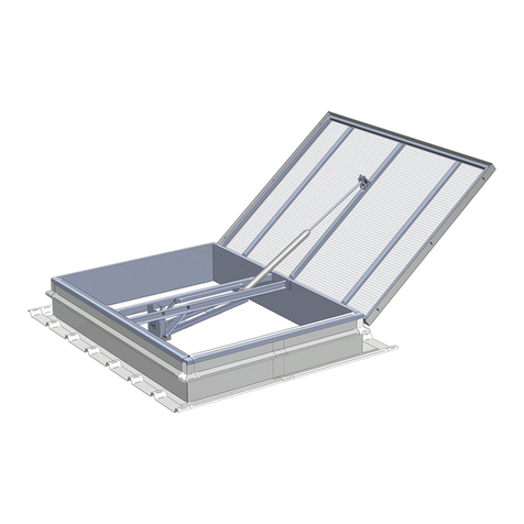
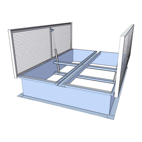
mercor mcr-PROLIGHT C User manual

Gdansk
Release 2.2.4 - 2014.03.28
2, Grzegorza z Sanoka
80-408 Gdansk
Phone No. +48 58 341 42 45
Phone / Fax No. +48 58 341 39 85
OPERATIONS AND MAINTENANCE MANUAL
Spot Smoke Vents
mcr-PROLIGHT - C, E, NG-A types
type C
type E
type NG-A

C,
E,
NG-A
T
YPE
mcr-PROLIGHT
V
ENTS
O
PERATIONS AND
M
AINTENANCE
M
ANUAL
(DTR)
Page 2 of 26
TABLE OF CONTENT:
1. INTRODUCTION. ..............................................................................................................3
2. PURPOSE OF SMOKE EXHAUST VENTS.......................................................................3
3. DESIGN AND OPERATING PRINCIPLES.........................................................................3
4. TRANSPORT and DELIVERY. ..........................................................................................6
5. INSTALLATION. ................................................................................................................6
5.1. Methods of smoke vent setting..........................................................................................8
6. WIND DEFELCTOR AND INLET DEFLECTOR...............................................................12
6.1. Wind deflectors................................................................................................................12
6.2. Inlet deflector...................................................................................................................13
7. VENT LEAF ADJUSTMENT.............................................................................................14
8. CONTROL.......................................................................................................................15
8.1. Pneumatic control............................................................................................................15
8.2. Electric control.................................................................................................................17
8.3. Ventilation function..........................................................................................................17
9. INSTALLATION OF DETACHED OPENING MECHANISM. ............................................19
10. VENTS WITH SECURITY BARS AND NETS.................................................................20
11. LEAF FILLING. ..............................................................................................................23
12. MAINTENANCE.............................................................................................................24
13. TERMS AND CONDITIONS OF WARRANTY AND SERVICE SUPPORT.....................25
14. CERTIFICATE OF CONFORMITY.................................................................................26
WARNING
Thermal valves in vents with pneumatic control are not armed for
safety reasons.
Such vents are NOT ready for operations.
Arm the thermal valve and screw in CO
2
cartridge (see section 8.1).

C,
E,
NG-A
T
YPE
mcr-PROLIGHT
V
ENTS
O
PERATIONS AND
M
AINTENANCE
M
ANUAL
(DTR)
Page 3 of 26
1. INTRODUCTION.
The present Operations and Maintenance Manual describes the purpose, design, operating
principles, correct assembling, and support of spot smoke vents as well as smoke and
ventilation dampers: C, E, and NG-A type mcr-PROLIGHT units. Furthermore, the
documentation includes additional data on operations, maintenance, and warranty conditions.
Not only will the consistency with the recommendations contained in this Manual ensure regular
functioning of the systems designed for smoke evacuation and/or ventilation, but also guarantee
safety to the users.
WARNING
All the works connected with assembling, operations, maintenance, and service support
of vents and skylights should be conducted in compliance with occupational health and
safety rules. Applicable personal protections should be used, including mostly
protections from fall from a different level. High-rise works, works on electric systems,
etc., should be conducted by competent personnel only.
2. PURPOSE OF SMOKE EXHAUST VENTS.
Smoke exhaust vents mcr-PROLIGHT are automatic appliances the primary function of which
consists in evacuation of smoke, fire fumes, and thermal energy from closed spaces (production
buildings; warehouse buildings; public buildings, etc.) to the outside, thus contributing to
protection of life and property thanks to:
• Maintenance of low smoke level on the escape routes;
• Assistance in fire fighting and extinguishing procedures by means of a bottom layer
featuring low smoke level;
• Protection of structural elements and equipment inside the building, and
• Reduction in fire damages produced by smoke, hot fire gases, and thermal
decomposition products.
Smoke exhaust vents may be used also as ventilation systems, smoke and ventilation dampers,
as well as additional roof lights.
Installation of smoke exhaust vents means a number of benefits to the investors, such as e.g.:
• Reduced fire resistance class of the building,
• Expansion of admissible fire zones, and
• Extension of fire routes.
mcr-PROLIGHT smoke exhaust vents are integral parts of smoke control systems which include
other components manufactured by MERCOR SA, such as e.g.: smoke vents in mcr-
PROLIGHT roof skylights and skylights, mcr-PROSMOKE smoke curtains, mcr 9705 and mcr
0204 smoke control units, and many other products.
mcr-PROLIGHT smoke exhaust vents are delivered with Certificate of Conformity No. WE
1488-CPD-0151/W issued by Instytut Techniki Budowlanej w Warszawie (Building
Research Institute in Warsaw) and confirming that the vents are manufactured in
compliance with the requirements contained in PN-EN 12101-2:2005 Standard.
3. DESIGN AND OPERATING PRINCIPLES.
Depending on individual requirements, MERCOR offers smoke exhaust vents on simple and
diagonal bases with wide array of structural opening dimensions and base heights.
All the steel elements are protected by means of hot dip or electrolytic zinc coating.
Standard base models are delivered inclusive of 20 mm thick thermal insulation. Thickness and
type of thermal insulation may be individually selected on request.

C,
E,
NG-A
T
YPE
mcr-PROLIGHT
V
ENTS
O
PERATIONS AND
M
AINTENANCE
M
ANUAL
(DTR)
Page 4 of 26
Available are active leaf filling types as follows:
• Cellular polycarbonate, 10 mm through 25 mm thick, with various light transmittance
values and heat transfer coefficients;
• Double and triple acrylic domes;
• Double and triple polycarbonate domes, and
• 'ALU' composite panels (e.g. aluminium-thermal insulation-aluminium).
C, E, NG-A type mcr-PROLIGHT vents are delivered with control systems specified below:
• Pneumatic control;
• Electric control, and
• Mechanical control.
Smoke exhaust vents and smoke and ventilation dampers are triggered either manually by the
user or automatically by means of thermal valves and mcr-type smoke control or fire signalling
central units.
C, E, NG-A type mcr-PROLIGHT smoke exhaust vents and smoke and ventilation dampers are
composed of fixed part (base) and active part (leaf with filling).
(a) C, E type
1. Filling
2. Clamp frame
3. Frame bearer
4. Spreader boom
5. Actuator holder
6. Smoke exhaust actuator
7. Ventilation actuator
(option)
8. Hooked bracket
9. Base
10. Base thermal insulation
11. Leaf seal
12. Base flange
13. Hinge
14. External detailing: zinc-
coated galvanised steel
sheet
(b) NG-A type
1. Filling
2. Clamp frame
3. Frame bearer
4. Spreader boom
5. Actuator holder
6. Smoke exhaust actuator
7. Ventilation actuator
(option)
8. Hooked bracket
9. Base
10. Base thermal insulation
11. Leaf seal
12. Base flange
13. Hinge
14. External detailing: zinc-
coated galvanised steel
sheet
Fig. 1. mcr-PROLIGHT vents: cross-section.

C,
E,
NG-A
T
YPE
mcr-PROLIGHT
V
ENTS
O
PERATIONS AND
M
AINTENANCE
M
ANUAL
(DTR)
Page 5 of 26
(a) polycarbonate panel
(b) ALU composite panel
(c) polycabonate and polyester
panels [Broof(t1) class]
(d) double acrylic dome
(e) triple acrylic dome
Fig. 2. Typical filling of mcr-PROLIGHT smoke vents.

C,
E,
NG-A
T
YPE
mcr-PROLIGHT
V
ENTS
O
PERATIONS AND
M
AINTENANCE
M
ANUAL
(DTR)
Page 6 of 26
4. TRANSPORT and DELIVERY.
C, E, NG-A type mcr-PROLIGHT vents are delivered as assembled units. In special
circumstances, however (additional external treatment, low base, etc.), vents may be supplied
as detached subassemblies components, except wind deflectors which always come separately
because individual elements must be protected from damages during the transport in order to
ensure road traffic safety. Unloading should be monitored by a person authorised by the
manufacturer. For unloading, use commonly available appliances or unload by hand, in
compliance with applicable occupational health and safety rules.
(a)
(
b)
Spreaders
Fig. 3. Transport by means of crane (a) and fork lift truck (b).
5. INSTALLATION.
Smoke vents should be installed in compliance with any applicable occupational health and
safety rules, specifically as regards high-rise works, using relevant personal protections.
Vents should be set on roof structural elements, such as e.g. purlins, trimmers, roof structural
sheet, reinforced concrete curbs, etc. Any elements which may produce collisions with the vent
leaf (entire range) should be removed.
Vents may be installed on steel, concrete, or timber roof structures. A recess (shelf) in the
bottom part of the vent base is designed for backing up and fixing the vent to the supporting
structure.
Selection of connectors depends on supporting structure materials in compliance with the table
below. Connectors should be spaced every 50 to 60 cm (max.).
Type of supporting structure Minimum diameter of connector
Steel min. Ø 4.8 mm
Concrete min. Ø 6 mm
Timber min. Ø 6 mm

C,
E,
NG-A
T
YPE
mcr-PROLIGHT
V
ENTS
O
PERATIONS AND
M
AINTENANCE
M
ANUAL
(DTR)
Page 7 of 26
Fig. 4. Method of setting mcr-PROLIGHT vent on the roof: connector spacing.
Smoke vent bases are adapted to roof works made of building felt, PVC membrane, or metal
sheet.
The entire perimeter of the vent top part is equipped with a galvanised steel sheet belt for
bolting roof works / cover. If the roof is covered with PVC membrane, the belt will be made of
PVC-coated sheet (option) in order to facilitate the installation.
Roof membrane should be welded or stuck to the PVC-coated steel sheet belt along the entire
perimeter of the base, in compliance with the best detailing practices. Building felt should be
first welded to the galvanised steel sheet belt along the entire perimeter of the base and
afterwards, fixed by means of mechanical methods.
Roof works must be fixed under the base edge. Roof works must not be laid out the base edge.
WARNING:
1. If the building felt is welded to the above mentioned sheet belt, vent leaf and
spacing sleeves SHOULD BE protected from the impact of fire / hot air by means
of safety screens.
2. Having installed the vent remove the protective film from external aluminium
parts of the vent (clamp frames; clamp strip) and from the vent filling (PCA;
composite panels; acrylic panels), otherwise the film may discolour the elements
and become difficult to remove.
3. If the vent is delivered in parts, pay special attention to the installation of
polycarbonate panels. Any damage to polycarbonate panel edge protective strip
will contribute to penetration of impurities into PCA cells and make the warranty
null and void.

C,
E,
NG-A
T
YPE
mcr-PROLIGHT
V
ENTS
O
PERATIONS AND
M
AINTENANCE
M
ANUAL
(DTR)
Page 8 of 26
5.1. Methods of smoke vent setting.
Fig. 5. Setting the steel base on the roof (DETAIL B) and method of sealing by means of roof membrane
or building felt (DETAIL A).
Detail A
1. Steel base
2. Base thermal insulation
3. Sheet belt for installation of roof membrane
or building felt
4. Roof membrane or building felt
5. Base edge
6. Leaf seal
7. Frame bearer
8. Clamp frame
9. Leaf filling
Fig. 6. Method of sealing with roof membrane or building felt (Detail A).

C,
E,
NG-A
T
YPE
mcr-PROLIGHT
V
ENTS
O
PERATIONS AND
M
AINTENANCE
M
ANUAL
(DTR)
Page 9 of 26
Detail B
(a) (b)
1. Vent steel base
2. Base thermal
insulation
3. Roof works with
membrane or felt
4. Roof thermal insulation
5. Reinforced concrete
slab
Fig. 7. Steel base on reinforced concrete slab: (a) membrane work; (b) felt work.
(a) (b)
1. Vent steel base
2. Base thermal
insulation
3. Roof works with
membrane or felt
4. Roof thermal insulation
5. Roofing sheet
6. Additional roof work
7. Steel supporting
structure
Fig. 8. Steel base on steel structure: (a) membrane work; (b) felt work.
(a) (b)
1. Vent steel base
2. Base thermal
insulation
3. Roof works with
membrane or felt
4. Roof thermal insulation
5. Steel supporting
structure
6. Roofing sheet
Fig. 9. Steel base on steel structure: (a) membrane work; (b) felt work.

C,
E,
NG-A
T
YPE
mcr-PROLIGHT
V
ENTS
O
PERATIONS AND
M
AINTENANCE
M
ANUAL
(DTR)
Page 10 of 26
(a) (b)
1. Vent steel base
2. Base thermal insulation
3. Roof works with
membrane or felt
4. Roof thermal insulation
5. Roofing sheet
6. Steel supporting
structure
Fig. 10. Steel base on steel structure: (a) membrane work; (b) felt work.
1. Skew vent steel base
2. Base thermal insulation
3. Roof works with membrane or felt
4. Roof thermal insulation
5. Roofing sheet
6. Steel supporting structure
Fig. 11. Skew steel base on steel structure.

C,
E,
NG-A
T
YPE
mcr-PROLIGHT
V
ENTS
O
PERATIONS AND
M
AINTENANCE
M
ANUAL
(DTR)
Page 11 of 26
1. Vent steel overlay base
2. Base thermal insulation
3. Overlay thermal insulation
4. Base overlay
5. Roof works with membrane or felt
6. Reinforced concrete curb
7. Roof thermal insulation
Fig. 12. Steel base on steel, timber, or reinforced concrete curb.
If mcr-PROLIGHT smoke vents are installed on pitched roofs, the bases shall be set so as
to position vent hinges at the lowest point on the roof.
Fig. 13. Vent installation on pitched roofs.
Roof pitch

C,
E,
NG-A
T
YPE
mcr-PROLIGHT
V
ENTS
O
PERATIONS AND
M
AINTENANCE
M
ANUAL
(DTR)
Page 12 of 26
6. WIND DEFELCTOR AND INLET DEFLECTOR
6.1. Wind deflectors.
Wind deflectors increase the active area of smoke vents. Standard models are made of
aluminium sheet.
Wind deflectors are delivered as customised bent elements or prefabricated products for
manual bending (with pre-marked recesses at the bending points), along with wind
deflectors holders fixed to the vent base.
Wind deflectors may be additionally equipped with reinforcing jibs which are factory fixed to
the wind deflectors.
Two Al / steel Ø 4.8 x 8 mm rivets per one assembling holder should be used for
installation of wind deflectors.
Fig. 14. Installation of wind deflector on the vent base: view from the outside of the vent.
Fig. 15. Installation of wind deflectors
on the vent base: view from the inside of the vent.
1
2
3
4
1
2
3
5
1. Wind deflector
2. Vent base with mineral wool filling
3. Assembling holder: place for wind
deflector riveting
4. Recesses for easy folding the wind
deflector by hand
5. Reinforcing jib (customised
dimensions)

C,
E,
NG-A
T
YPE
mcr-PROLIGHT
V
ENTS
O
PERATIONS AND
M
AINTENANCE
M
ANUAL
(DTR)
Page 13 of 26
6.2. Inlet deflector.
Inlet deflector slats will increase active aerodynamic efficiency of C and E type vents,
which means increased smoke venting surface. Fixed at the bottom part of the vent base,
the inlet deflector is made of zinc coated steel sheet or, as an option, of aluminium sheet,
and may be painted in any RAL chart colour. The inlet deflector is pre-fixed to the vent in
transport position which should be changed to working position once the vent is installed
on site:
•Undo the assembling holder screws on Side B of the slat (existing bean-shaped
holes);
•Undo the assembling holder screws on Side B of the slat (existing Ø 6.5 mm
holes);
•Lower the inlet deflector to the working position; mind the existing holes, and
•Tighten the clamping screws (use locked nuts only).
Fig. 16. Inlet deflector (assembling holders in transport position).
Fig. 17. Inlet deflector in transport position (inside the vent).
2
5
1
3
4
1. Inlet deflector (Side A with bean-shaped
holes)
2. Inlet deflector (Side B with Ø 6.5 mm
holes)
3. Assembling holder

C,
E,
NG-A
T
YPE
mcr-PROLIGHT
V
ENTS
O
PERATIONS AND
M
AINTENANCE
M
ANUAL
(DTR)
Page 14 of 26
Fig. 18. Inlet deflector in working position.
7. VENT LEAF ADJUSTMENT.
(HOOKED BRACKET, EYE BOLTS AND 'T' BOLTS)
Vent leaf is linked with actuator via the hooked bracket which is locked on the 'T' bolt.
Pneumatic actuators and electric spindle actuators are connected with the hooked bracket
by means of an eye bolt which is screwed into the actuator piston rod / spindle. Vent leaf
clearance is minimized by screwing in the eye bolt or adjusting the 'T' bolt. Eye bolt
or 'T' bolt should be protected from undoing by means of a retaining nut. If an
additional 230 V~ electric actuator is used for ventilation to co-operate with the pneumatic
actuator, 'T' bolt will be screwed into the toothed bar or 230 V~ electric actuator spindle.
Fig. 19. 'T' bolt. Fig. 20. Hooked bracket. Fig. 21. Eye bolt.

C,
E,
NG-A
T
YPE
mcr-PROLIGHT
V
ENTS
O
PERATIONS AND
M
AINTENANCE
M
ANUAL
(DTR)
Page 15 of 26
Fig. 22. Connection of actuators with hooked bracket.
8. CONTROL.
Smoke exhaust vents and smoke and ventilation dampers make use of opening and
closing mechanisms which compose the systems for smoke exhaust or exhaust &
ventilation control. Depending on the components, smoke control systems may be:
• Pneumatic,
• Electric,
• Mechanical.
Depending on the method of control, mcr-PROLIGHT smoke vents include pneumatic
actuators with thermal valves or electric actuators as well as pneumatic actuators and
electric actuators as additional equipment for natural ventilation control.
The user must immediately notify the service support (see section 12) of any such failure
of control system which prevents the vent leaf from closing.
In case of emergency the user can immediately close the vent leaf without waiting for the
service team by switching the defective actuator off (e.g.: disconnect the eye bolt from the
hooked bracket or undo the eye bolt from the actuator or disconnect actuator E from the
fixing bracket), shut the leaf and lock it in closed position.
8.1. Pneumatic control.
Depending on system configuration, the vent may additional pneumatic pipes (such as e.g.
copper / steel tubes running towards the alarm box with fuses).
Threaded connections of the union with valves, actuators, etc., should be sealed with
suitable chemical preparations, such as e.g. Loctite 243 (recommended) or Teflon® tape to
be winded on the thread. Loctite 243 should be coated drop by drop (2-3) onto the thread.
Once the threaded connection is tightened, Loctite 243 will set and seal the connection
thus protecting it from uncontrolled loosening (which is important in the case of actuator
connections). To undo such unions, the user is required to employ manual tools.
Vents with pneumatic control are equipped with cords which limit the range of leaf
movement. Cords should be released prior to start-up (they should freely hang down).

C,
E,
NG-A
T
YPE
mcr-PROLIGHT
V
ENTS
O
PERATIONS AND
M
AINTENANCE
M
ANUAL
(DTR)
Page 16 of 26
Fig. 23. Pneumatic system flexible tubing: assembling method.
Fig. 24. Connection of union with copper / steel tube.
WARNING
For safety reasons, smoke vent thermal valve is not armed. Once the vents are
installed on the roof, eliminate potential leaf clearance by adjusting the leaf and
arm the thermal valve.
Thermal valve arming:
- Make sure whether, or not, the striker tightening spring (1) is unscrewed; if
negative, it should be unscrewed home by
hand.
- Install alcohol fuse (2) in the seat of gas flow
regulator placing its pointed tip towards the
body; tighten the phial press bolt by hand.
- Place the valve slider (4).
- Manually tighten the striker spring home by
means of the screw (1).
- Make sure whether, or not, the fuse striker is
hidden. The seal must be present in the fuse
seat.
- Screw in CO
2
cartridge (3) by hand.
Nut
Pipe
Clamping ring
Sleeve (plastic tubing)
Body
3
1
2
4
Copper tube
Clamping ring
Nut
Body

C,
E,
NG-A
T
YPE
mcr-PROLIGHT
V
ENTS
O
PERATIONS AND
M
AINTENANCE
M
ANUAL
(DTR)
Page 17 of 26
Fig. 25. Thermal valve.
Fig. 26. Pneumatic actuator PUAV: direction of releasing the lock.
Pneumatic actuator used in smoke evacuation systems are equipped with internal locks
which prevent completely open vent leaves from closing. Shown below is the method of
closing the vent leaves following the emergency opening when the systems have no
remote closing option:
1. Decompress CO
2
: unscrew the fuse from thermal trigger or alarm box (Warning:
High pressure; undo slowly since the fuse may defrost).
2. Release actuator’s locks (5): lift them in the same direction as actuator working
movement (follow the arrow - see Fig. 25).
3. Lower the vent leaf.
4. Check the leaf closing condition.
5. Place a new CO
2
fuse inside thermal trigger or alarm box.
6. In case of need replace thermal fuse [alcohol phial (2)].
8.2. Electric control.
Leaf opening control system with a 24 V DC electric actuator for smoke evacuation is
factory installed inside the vent. Even so, it should be set for operations: connect the
electric actuator eye bolt with the hooked bracket bolt and make suitable adjustment to get
the bracket reliably locked on bolt 'T' as well as to make simultaneously the electric
actuator switch off once the vent is closed thanks to the limit switch instead of the overload
switch.
Method of connecting mcr-W / mcr-WSG actuator (wire poles):
Brown wire
+
Spindle moves in
Brown wire
-
Spindle moves
out
Blue wire – Blue wire +
mcr9705 and mcr0204 smoke exhaust and ventilation control units inclusive of mcrR0424
and/or mcrR0448 extension modules should be used for the purpose of control and power
supply of mcr-W / mcr-WSG electric actuators of mcr-PROLIGHT vents.
We recommend no more than 30° deflection of the vent leaf with 24V actuator, which
corresponds to the opening time of about 20 sec.
8.3. Ventilation function.
There are two embodiments:
- Pneumatic actuators with applicable systems, or
- An additional 230 V~ electric actuator (see the figure below).
5

C,
E,
NG-A
T
YPE
mcr-PROLIGHT
V
ENTS
O
PERATIONS AND
M
AINTENANCE
M
ANUAL
(DTR)
Page 18 of 26
Typically, ventilation electric actuator is not factory installed for transport reasons. It should
be mounted in the opening system bracket by means of ST12-1/8 bolts (Exxx-230
actuator) or screw bolts (JMB actuators) delivered together with the actuator. Screws ST12
should be protected from unscrewing by means of Loctite 243 or similar preparation.
Actuator has a T-shaped screw which should be installed instead of eye bolt. Hooked
bracket should be locked on the 'T' screw.
We recommend using a weather automatic control unit, such as e.g. mcrP054, in the
ventilation control system. With this unit, the system will close open vents in case of strong
wind or rainfall and hence, protect user's property and vent structures from damages.
Fig. 27. Ventilation control actuator Fig. 28. 'T' type screw. Fig. 29. ST12 1/8 screw.
(Exxx-230 type).
Circuit diagram 230 VAC Ventilation electric actuator
(a) Exxx - 230 V type actuator has two circuits:
• operating: movement sense control (black / brown / blue wires);
• signalling (2 x white wires; actuator opening signalling:
neutral contact).
Fig. 30. Exx-230 type actuator
(b) JMBB-500-300-LA type actuator has two circuits:
• operating: movement sense control
(wires: brown / black 1 - blue),
• signalling (wires: black 2 / black 3;
actuator opening signalling: neutral contact).
Fig. 31. JMBB-500-300-LA actuator.
black
brown
blue
white
white
Brown
black 1
blue
black 2
black 3

C,
E,
NG-A
T
YPE
mcr-PROLIGHT
V
ENTS
O
PERATIONS AND
M
AINTENANCE
M
ANUAL
(DTR)
Page 19 of 26
9. INSTALLATION OF DETACHED OPENING MECHANISM.
If the control system is delivered as a separate item, the installation should follow the
instructions specified below:
A. Align the control system with the axis of the smoke vent.
B. Fasten the control system to the vent
base using 12 self-tapping bolts ø 6.3 for
metal sheets.
C. Connect the actuator with the hooked
bracket fastened to the vent leaf: remove
the split pin and push the mandrel through
the eye bolt.
D. Subject to type of control, connect the unit with the system in compliance with section 9
and adjust it in compliance with section 8.
Control system
Smoke vent

C,
E,
NG-A
T
YPE
mcr-PROLIGHT
V
ENTS
O
PERATIONS AND
M
AINTENANCE
M
ANUAL
(DTR)
Page 20 of 26
10. VENTS WITH SECURITY BARS AND NETS.
mcr-PROLIGHT PLUS smoke vents may be equipped with anti-burglar bars (C and E
types) or nets (C, E, and NG types).
Security nets are delivered as integrated elements along with the vents; they are resistant
to the maximum 1,200 J impact of a large soft solid.
Fig. 32. mcr-PROLIGHT PLUS vent with security net.
Security bars comply with Class 2 requirements of PN-ENV 1627:2006 Standard,
concerning the resistance to burglary; they are resistant to the < 1,200 J impact of a large
soft solid. Bars are delivered as separate elements. Install the bars following the
instructions below:
I. Installation of the bracing on the spreader boom of the opening system.
1
2
L
L/2
- Place the bar bracing at the vent half width.
- Install the bracing by means of self-tapping bolts ø 6.3 on the vent base through the holes
in the catch plate.
- Bracing should be fastened to the opening mechanism spreader boom from the bottom
and from the top, by means of self-tapping bolts ø 6.3.
1. Vent opening mechanism spreader boom.
2. Bar bracing with catches.
L: vent width.
Arrows indicate the places for fastening the bolts.
Other manuals for mcr-PROLIGHT C
1
This manual suits for next models
2
Table of contents
Other mercor Fan manuals