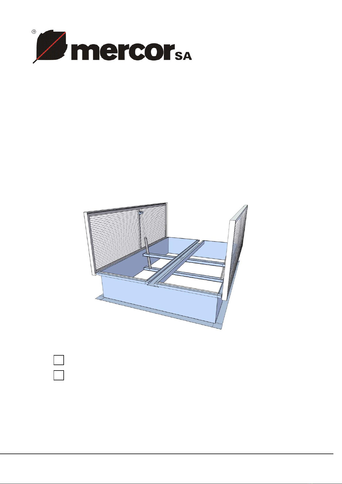
mcr-PROLIGHT VENTS,TYPE:DVP, DVPS
OPERATION AND MAINTENANCE MANUAL
Page 3 of 30
1. INTRODUCTION
This operation and maintenance manual (OMM) allows the user to learn the purpose, design,
principle of operation and correct installation of mcr-PROLIGHT smoke vents and smoke &
ventilation vents type DVP and DVPS. The documentation also covers additional information
on the conditions for use, maintenance and terms of the product's warranty.
Observing the guidelines contained herein will ensure the proper functioning of systems in
terms of their smoke exhausting and/or ventilation function, and the safety of system operators.
NOTE
Any works related with installation, operation, maintenance and servicing of the vents
and skylights may only be performed in compliance with SHE requirements, and with use
of appropriate personal protective equipment - including fall arresting devices. Any
works necessitating working at height in order to make electrical connections, etc. may
only be performed by duly licensed persons.
2. PURPOSE OF DEVICE
mcr-PROLIGHT smoke vents are automatic smoke venting devices. The principal function of
mcr-PROLIGHT smoke vents is the removal of heat energy, fire gases, and smoke from
enclosed spaces (production floors, storage rooms, public amenity buildings, etc.) outside the
building, contributing to the protection of life and property, through:
• maintaining escape routes in a state of moderate smoke intensity,
• facilitating fire fighting and rescue operations by providing a bottom corridor with
moderate smoking intensity,
• ensuring protection for the building structure and its equipment,
• limiting fire damage caused by smoke, hot burning fumes and thermal decomposition
byproducts
The smoke vents may also serve the purpose of ventilation vents, smoke & ventilation vents, or
roof skylights.
The use of smoke vents provides the following opportunities to the Investor:
• lowering the building's fire resistance grade
• extending permissible fire zones,
• elongating evacuation routes
mcr-PROLIGHT smoke vents are part of a smoke control system that comprises other
MERCOR SA products, including, among others: mcr-PROLIGHT smoke vents in continuous
skylights and single skylights, mcr-PROSMOKE smoke curtains, mcr 9705 and mcr 0204 control
units, and others.
mcr-PROLIGHT smoke vents have a Certificate of Conformity WE 1488-CPD-0151/W,
issued by the Institute for Building Technologies in Warsaw, certifying the conformance
of the vents design with the requirements of PN-EN12101-2:2005, and Certificate of
Conformity 1396-CPD-0040 issued by Fires s.r.o., NB 1396, Slovakia, certifying the
conformance of the vents design with the requirements of EN 12101-2:2003.
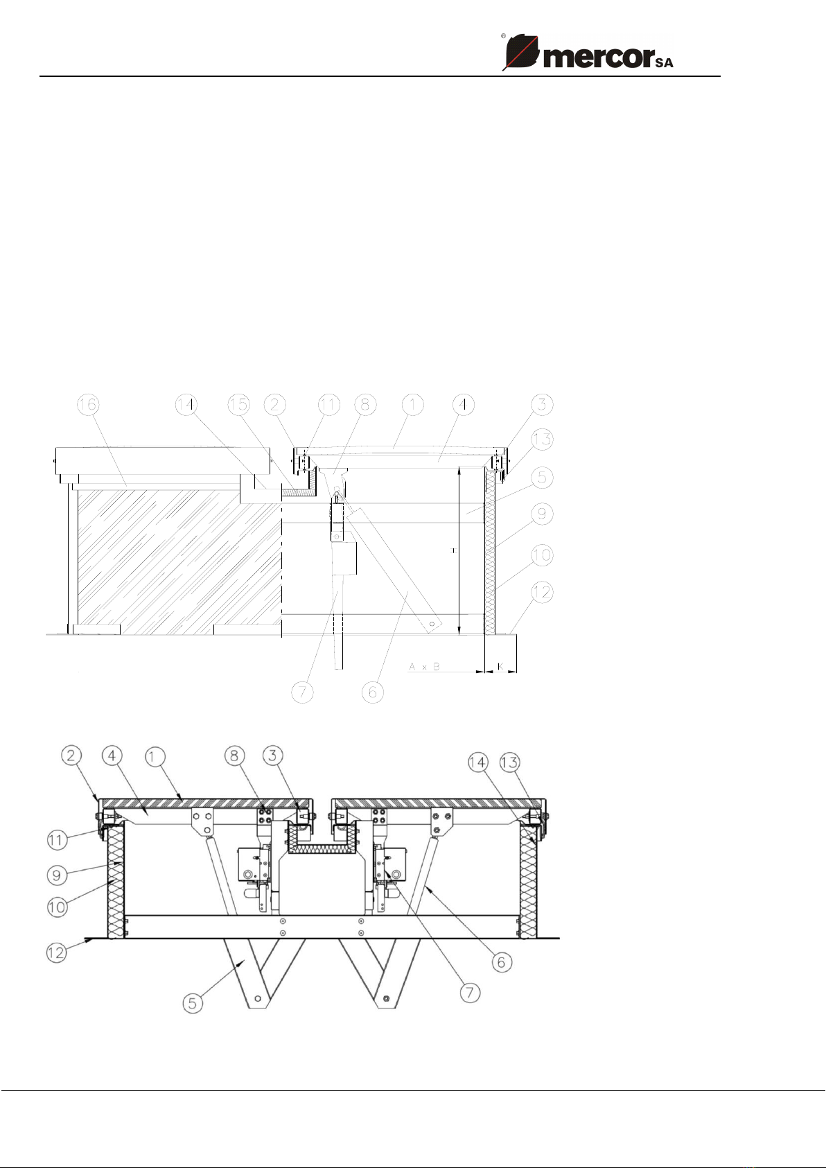
3. DEVICE DESIGN AND PRINCIPLE OF OPERATION
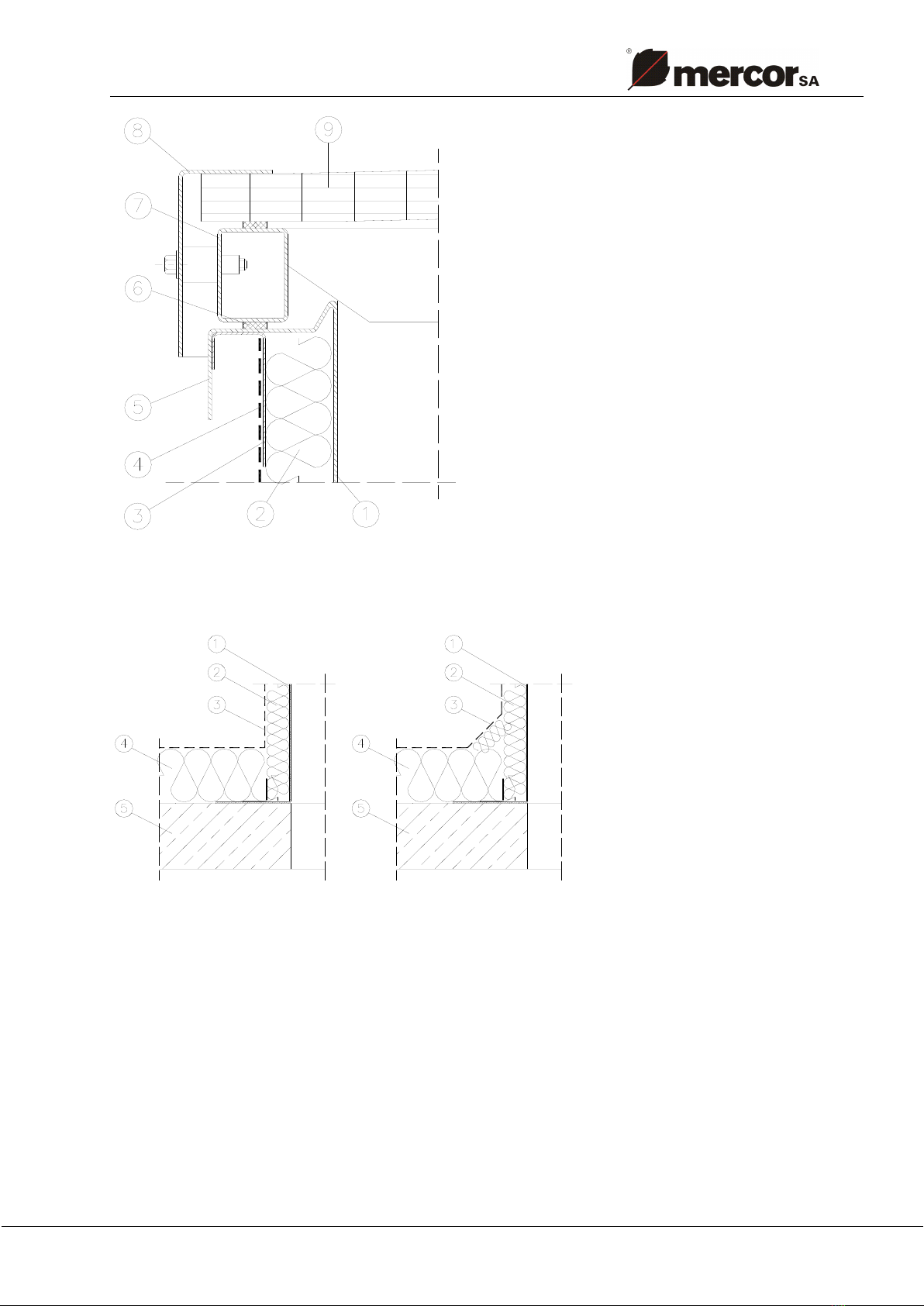
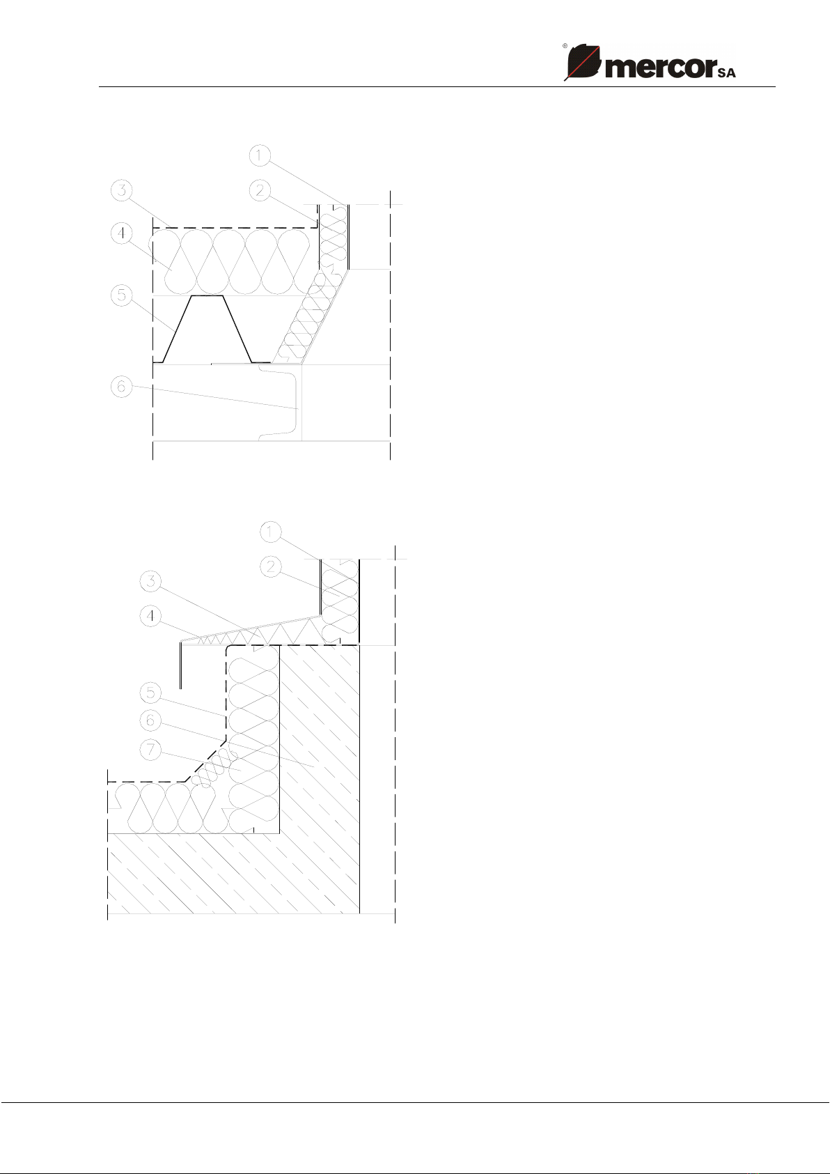
Depending on the customer's individual requirement, MERCOR offers double-leaf smoke vents
and fixed and opening skylights, on straight bases, in a broad range of clear dimensions and
base heights.
All steel elements of the vents are protected with a zinc coat, applied using hot-dip or galvanic
method.
In standard, the bases are supplied with thermal insulation of thickness 20 mm. Custom
thickness and thermal insulation type is possible.
The glazing options for the opening leaf are as follows: