Installation manual of mcr PROLIGHT continuous rooflight with smoke vents
Page 2 of 104
Table of Contents
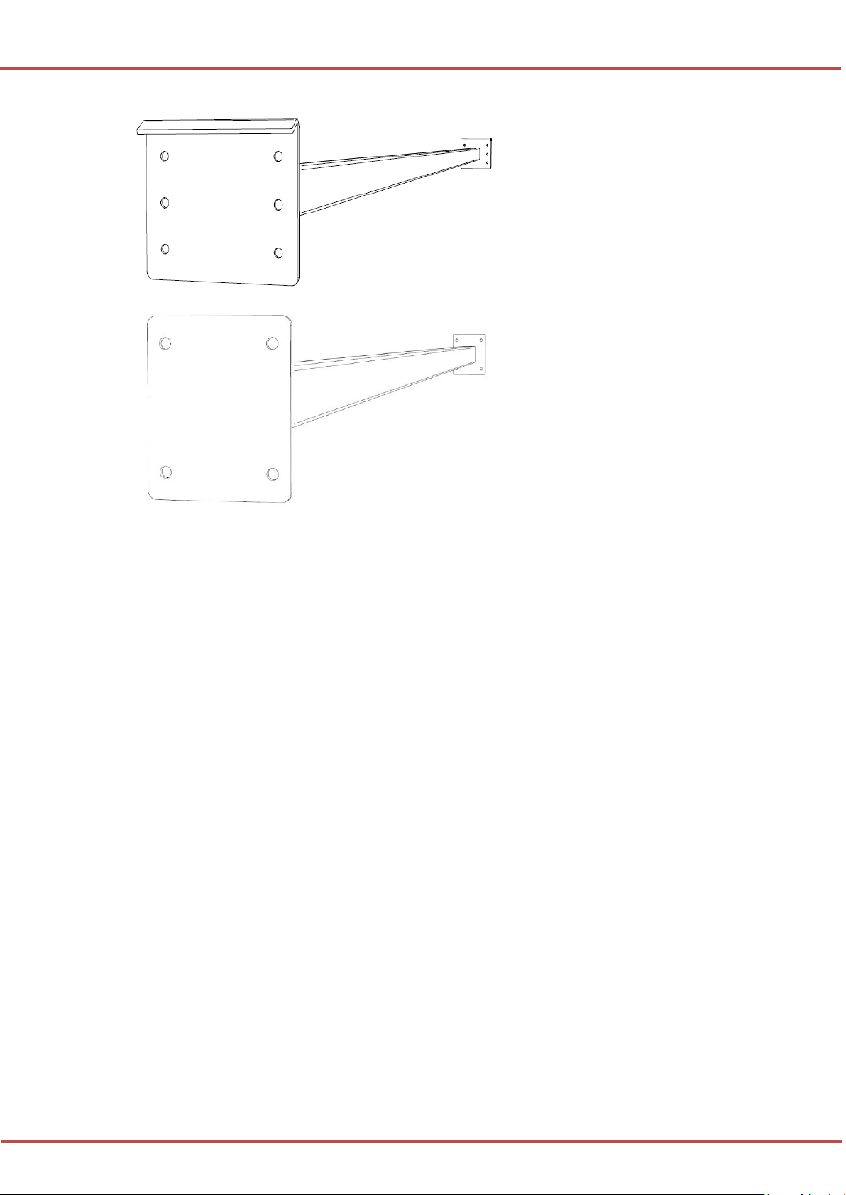
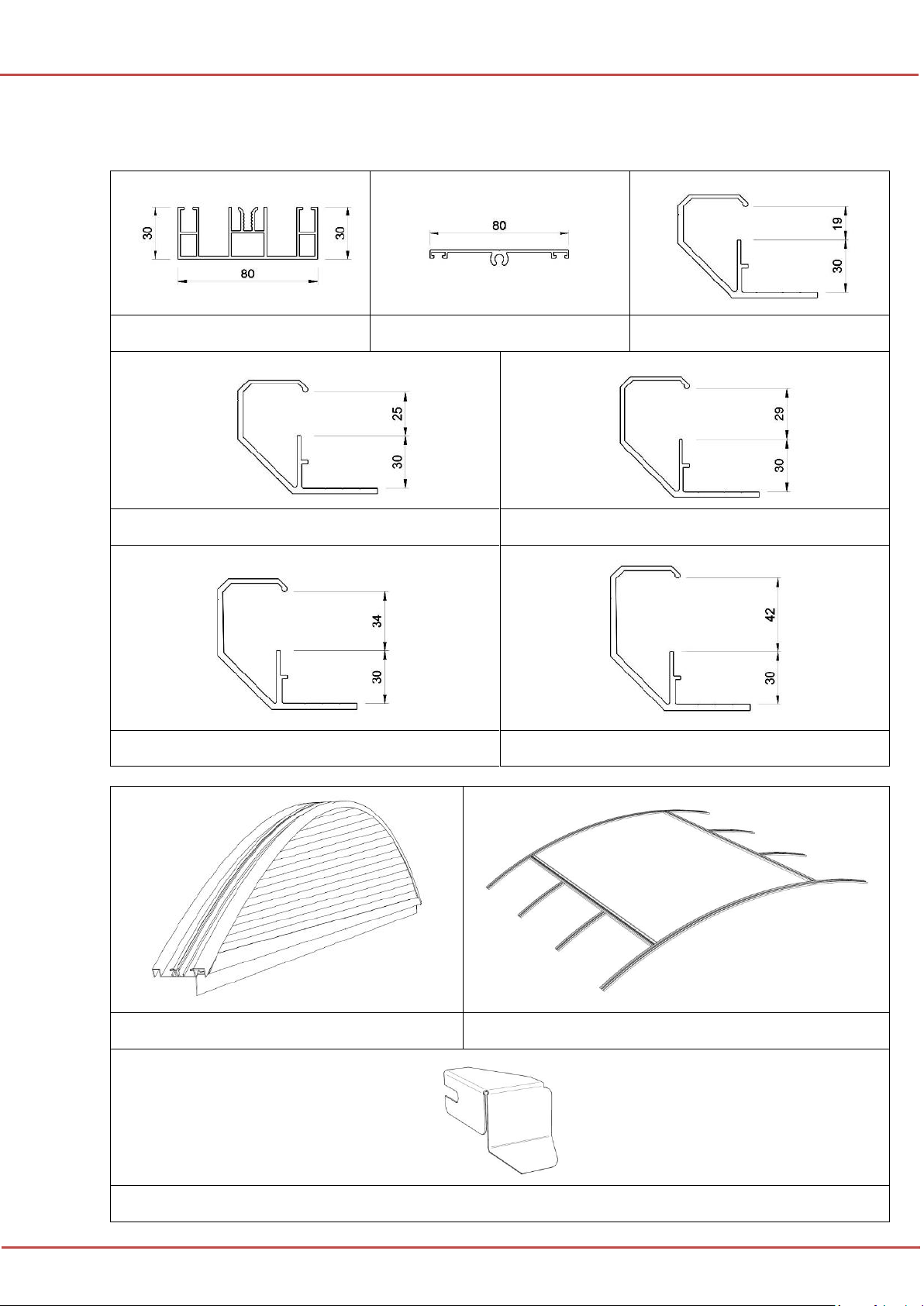
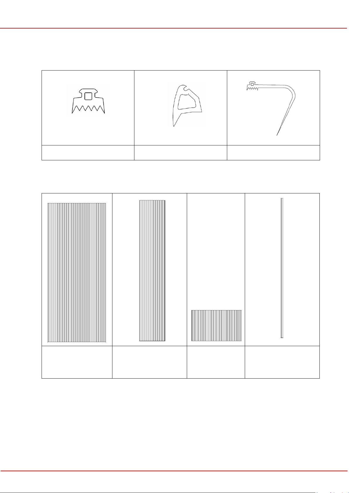
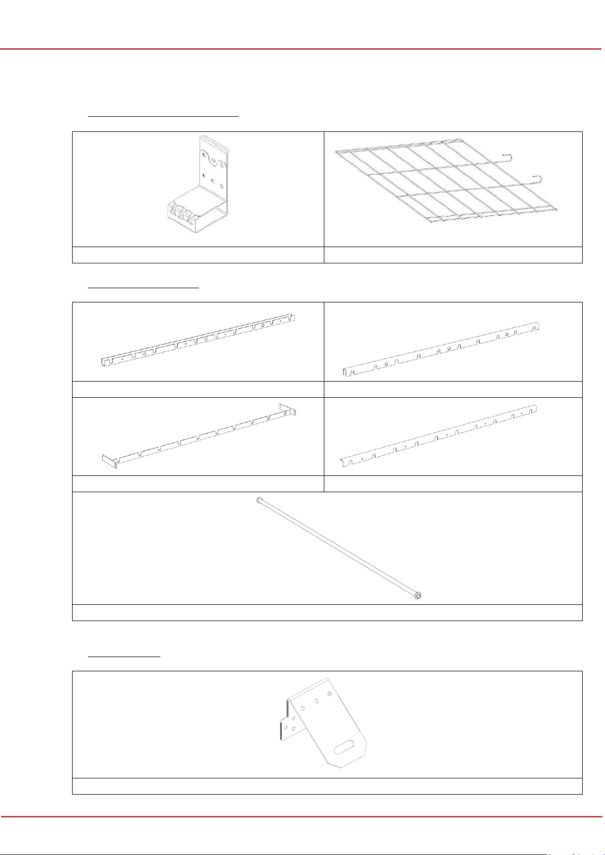
I. Components of continuous rooflight and components of continuous rooflights
with sandwich panels........................................................................................................3
II. Installation of the rooflight base.....................................................................................13
III. Installation of an overlay base ........................................................................................18
IV. Installation of a safety nets / an anti-burglar grids..........................................................20
A. Installation of a safety net...............................................................................................20
B. Installation of the anti-burglar grid.................................................................................23
C. Installation of PAS anchorage points..............................................................................25
V. Double glazings –possible configurations and installation sequence............................27
VI. Assembly of the top section of the continuous rooflight................................................37
VII. Additional operations limiting errors in roofing works at the tympanum panel ............54
VIII. 1200 J reinforcements to the top section structure..........................................................55
A. Types of 1200J reinforcements.......................................................................................55
B. Spacing of 1200 J braces ................................................................................................56
C. Installation of 1200 J reinforcements..............................................................................58
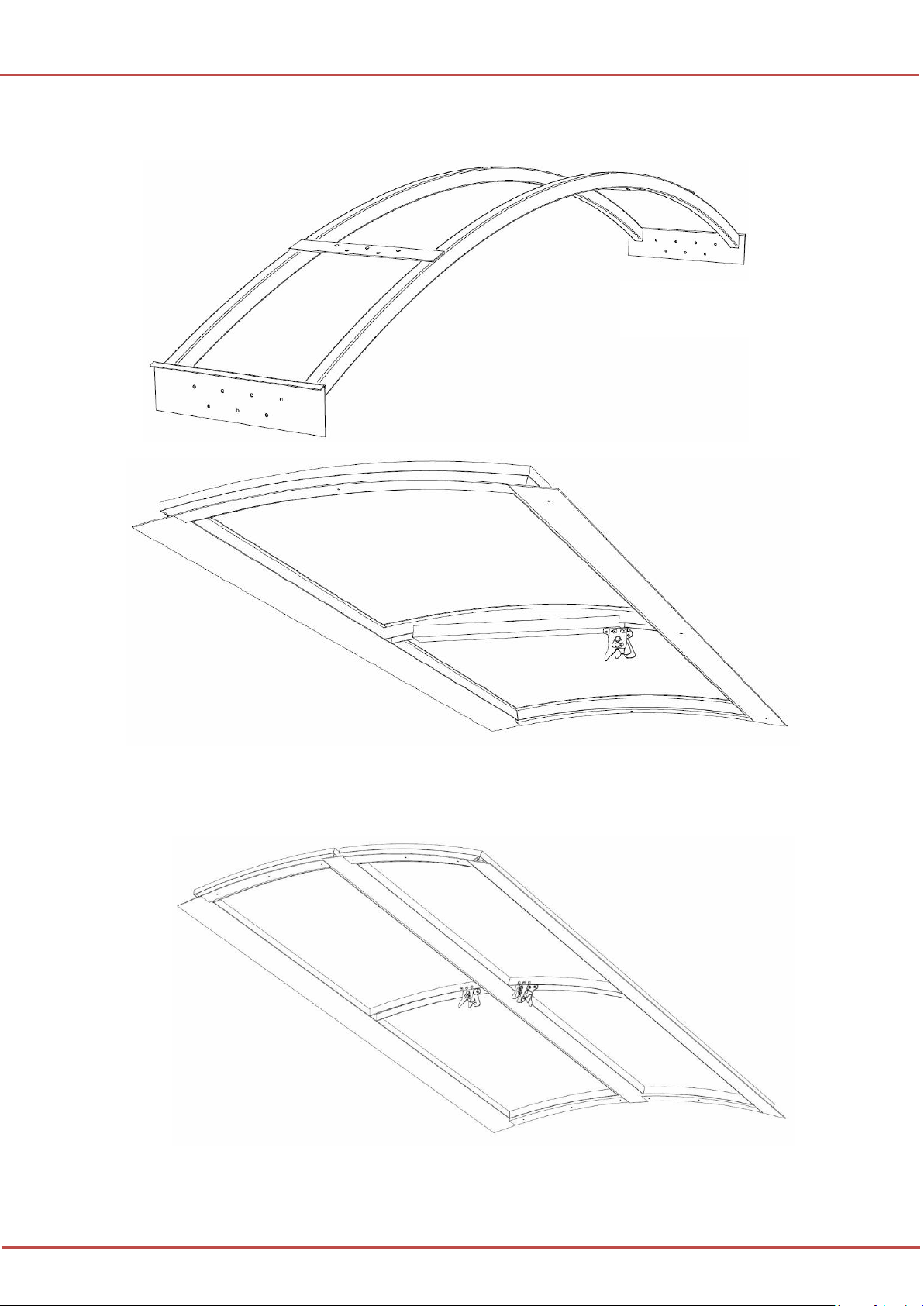
IX. Assembly of triangular rooflight.....................................................................................61
X. Installation of a double-leaf vent integrated into a continuous rooflight........................67
XI. Installation of a single-leaf vent in a continuous rooflight.............................................74
XII. Installation of wind deflectors ........................................................................................78
XIII. Instruction for the installation of the continuous rooflight crossing the roof ridge........80
XIV. Roof ridge crossing: how to install the 1200 J reinforcements.......................................98