9
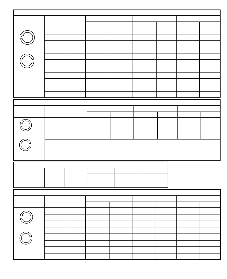
ON-IRM48C
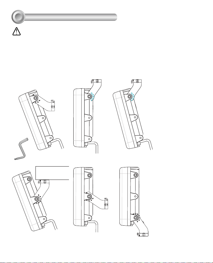
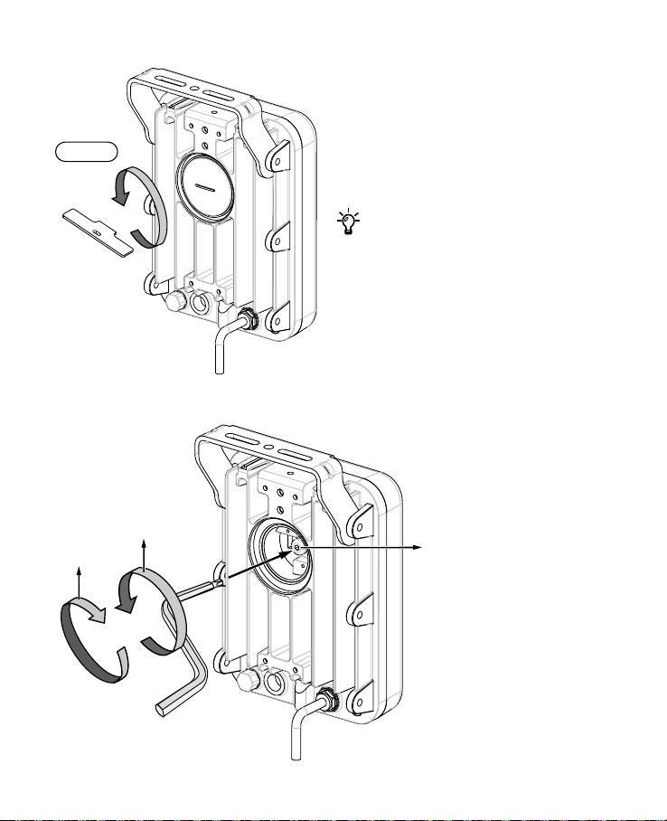
Rotate
direction
Full circle Beam angle Single mount Double mount Triple mount
Distance(m) Width(m) Distance(m) Width(m) Distance(m) Width(m)
0 80° 60 100.7 84.9 142.4 103.9 174.4
1 77° 62 98.6 87.7 139.5 107.4 170.8
2 74° 64 96.5 90.5 136.4 110.9 167.1
3 66° 67 87.0 94.8 123.1 116.0 150.7
4 63° 69 84.6 97.6 119.6 119.5 146.5
5 60° 71 82.0 100.4 115.9 123.0 142.0
6 55° 75 78.1 106.1 110.4 129.9 135.2
7 52° 79 77.1 111.7 109.0 136.8 133.5
8 50° 82 76.5 116.0 108.2 142.0 132.5
9 45° 86 71.2 121.6 100.8 149.0 123.4
10 40° 90 65.5 127.3 92.7 155.9 113.5
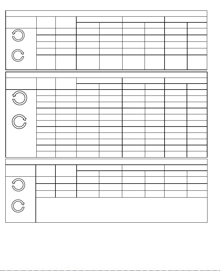
ON-IRM48D
Rotate
direction
Full circle Beam angle Single mount Double mount Triple mount
Distance(m) Width(m) Distance(m) Width(m) Distance(m) Width(m)
0 120° 45 155.9 63.6 220.5 77.9 270.0
1 105° 50 130.3 70.7 184.3 86.6 225.7
2 90° 55 110.0 77.8 155.6 95.3 190.5
Counter-clockwide
Narrower
Clockwide
Narrower
Clockwide
ON-IRM48E
Rotate
direction
Full circle Beam angle Single mount Double mount Triple mount
Distance(m) Distance(m) Distance(m)
Fixed angle N/A 180° 40 56.6 69.3
ON-IRM48AW5
Rotate
direction
Full circle Beam angle Single mount Double mount Triple mount
Distance(m) Width(m) Distance(m) Width(m) Distance(m) Width(m)
0 40° 100 72.8 141.4 102.9 173.2 126.1
1 36° 107 69.5 151.3 98.3 185.3 120.4
2 30° 127 68.1 179.6 96.3 220.0 117.9
3 27° 137 65.8 193.7 93.0 237.3 113.9
4 24° 150 63.8 212.1 90.2 259.8 110.4
5 16° 206 57.9 291.3 81.9 356.8 100.3
6 15° 215 56.6 304.1 80.1 372.4 98.1
7 10° 250 43.7 353.6 61.9 433.0 75.8
Narrower
Clockwide