MerCs ME-ELR-DD User manual

02 4047 0777 www.mercs.com.au02 4047 0788
MerCs Pty Ltd, 55 Pendlebury Rd, Cardi, NSW, 2285, Australia | 2018 V1.1
Earth Leakage Relay
User Manual
ME-ELR-DD
• Adjustable sensitivity
• Adjustable time delay
• LED Status indicators
• Leakage current indication
• Remote test and reset switching
• DIN rail mounting
• Current measurement based on fundamental frequency, prevents nuisance tripping
• Dial adjustment for ease of use
• Robust casing protects the unit from external interference
• Serial Number Tracked
Features
The ME-ELR-DD are microprocessors based earth leakage relays designed for measure the
low-level leakage or unbalanced currents due to insulation loss in conductors or equipment to be
protected. A zero phase current transformer is used to sense the leakage current. All conductors
of the circuit to be protected shall go through the ME-T.
For better fault preventive control of the system or equipment, ME-ELR-DD comes with a pre-
fault alarm contact and a positive safety contact. The pre-fault alarm contact is energized when-
ever the leakage current exceed 50% of the sensitivity setting, I n. The positive safety contact is
energized if the relay is power up and function correctly.
DescriptionApplications
Technical Data
• Industrial equipment protection
• Personnel protection from Earth Leakage
faults
• Suitable for low voltage distribution
protection
Auxiliary Supply
ME-ELR-DD-110A 94 ~ 127 VAC
ME-ELR-DD-24A 21 ~ 28 VDC
Rated frequency 50Hz
VA rating 3 VA typical
Setting Ranges
Sensitivity adjustment
30mA, 50mA,
0.10A – 1.00A (Step = 50mA),
1.00A – 5.0A (Step = 1.00A)
Delay time adjustment 0.05s - 0.5s (Step = 0.05s)
Record
Fault record 3 latest tripped fault currents
Storage Non-volatile memory
Input
Remote reset N.O. dry contact
Outputs
Trip contact 5A / 250V AC1
Positive safety contact 5A / 250V AC1
Pre-fault alarm contact 5A / 250V AC1
Contact Specication
Contact arrangement 3 latest tripped fault currents
Contact material Non-volatile memory
Expected electrical life 100,000 at rated current
Expected mechanical life 5x10⁶operations
02 4047 0777 www.mercs.com.au02 4047 0788
MerCs Pty Ltd, 55 Pendlebury Rd, Cardi, NSW, 2285, Australia | 2020 V1.1
Earth Leakage Relay ME-ELR-DD
Indicator Status
Trip Alarm FUNC DP DATA
0 0 0 0 0 No auxiliary power supply
0 0 0 0 1 Normal condition, no tripping
0 B X X X Leakage current exceeded 50% of the sensitivity
setting, I△n
0 FB X X X Leakage current exceeded 85% of the sensitivity
setting, I△n. Time delay countdown started
1 1 0 0 B Delay time lapsed and relay tripped
0 X 1 0 1 Scroll through setting
0 X 1 1 1 Scroll through records
0 X B 0 1 Programming mode
Light Indicators
The indicators display the status of the system as follow:
Indicators
Pre-fault alarm Red indicator
Time delay Red indicator
Leakage trip 7-segment display &
red indicator
ME-T fault 7-segment display & red indicator
Real-time leakage current 7-segment display
Zero-Phase Current Transformer
To operate with Mikro's ME-T series of current transformer
Delay time adjustment 0.05s - 0.5s (Step = 0.05s)
Mechanical
Mounting method Standard 35mm DIN rail mounting
Approximate weight 0.38kg (excluding ME-T)
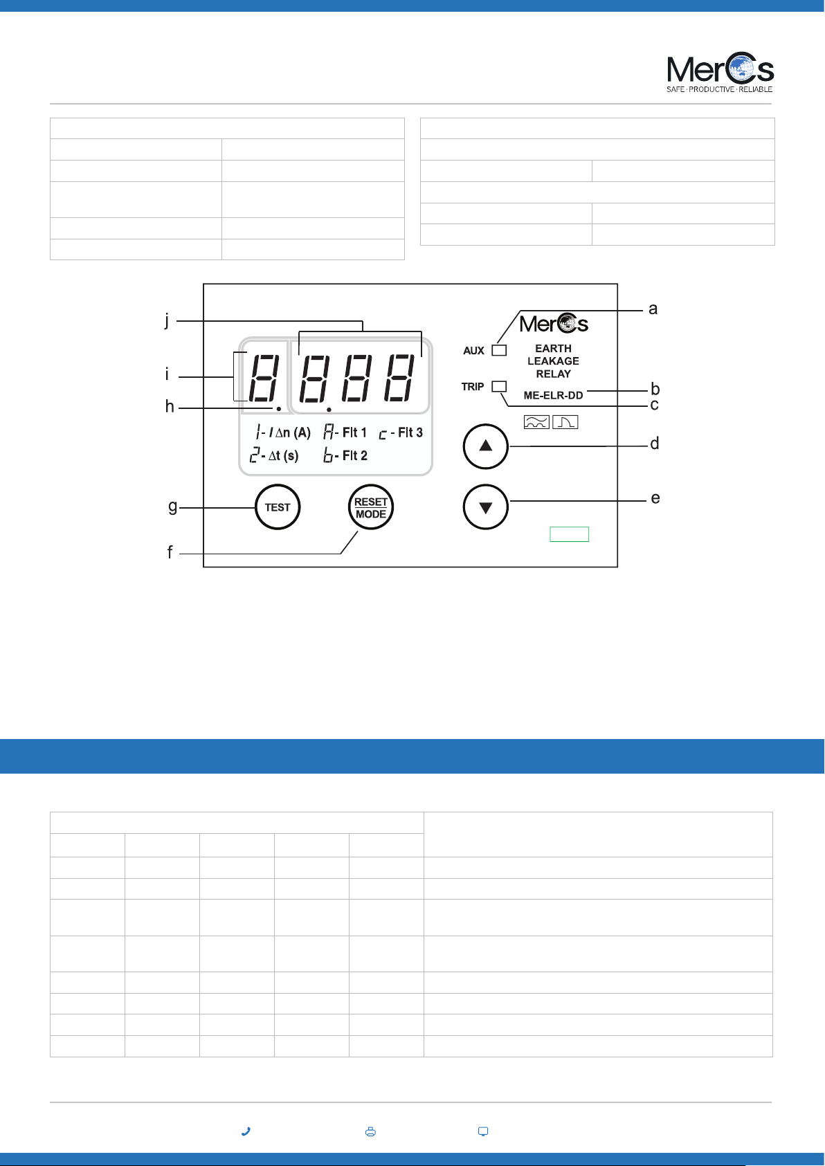
a - Trip status indicator
b - Model
c - Alarm status indicator
d - Up button
e - Down button
f - Reset/mode button
g - Integral test button
h - DP indicator
i - FUNCTION indicator
j - DATA indicator
Symbols
I△n - Sensitivity setting
△t - Time delay setting
Flt 1 - Fault record 1 (Newest)
Flt 2 - Fault record 2
Flt 3 - Fault record 3 (Oldest)

02 4047 0777 www.mercs.com.au02 4047 0788
MerCs Pty Ltd, 55 Pendlebury Rd, Cardi, NSW, 2285, Australia | 2020 V1.1
Earth Leakage Relay ME-ELR-DD
e. Program Setting
Step 1: Press “RESET” button until the function digit shows the required function.
Step 2: Press the “UP” and “DOWN” button simultaneously and hold for 1 sec to enter programming mode. The function digit will blinks
to indicates the relay is in programming mode.
Step 3: Use the “UP” or “DOWN” button to select the desired value.
Step 4: To save the selected value, press the “UP” and “DOWN” button simultaneously and hold for 1 sec again. It will exit the program-
ing mode with data digits displaying new setting.
To exit programming mode without saving the selected setting, press the “RESET” button once.
Push Button Operations
a. Integral Trip Test:
Press the “TEST” button to perform an integral test on the relay ranging from analog sensing circuitry to output contact(s) of the relay
as well as the relay indicators and display.
b. Trip Reset:
Press the “RESET” button to reset the relay when tripped
c. CT Fault:
Press the “RESET” button to reset the relay after xing the ME-T connection error. No reset function is carry out if the fault is not
cleared.
d. View Setting:
When the relay is not under tripped condition or ME-T fault condition pressing the “RESET” button will scroll through the various
functions.
FUNC DP DATA
o o Real time leakage current
1 o Sensitivity setting
2 o Delay time setting
A on Fault record 1 (Newest)
b on Fault record 2
c on Fault record 3 (Oldest)
Message Description
‘ Ct’ Error in ME-T connection
‘tSt’ Relay tripped under test mode
Table 2: Function codes
Table 3: Display messages
Table 1: System status
1 = ON
0 = OFF
X = Don’t care
B = Normal blinking
FB = Fast blinking
FUNC = FUNCTION

02 4047 0777 www.mercs.com.au02 4047 0788
MerCs Pty Ltd, 55 Pendlebury Rd, Cardi, NSW, 2285, Australia | 2020 V1.1
Earth Leakage Relay ME-ELR-DD
Connection Diagrams
Case Dimension
Record
The ME-ELR-DD incorporates a fault record function. It records the 3 latest tripped faults current and stored in non-volatile memory. No data
is recorded if the tripping is triggered by integral test button.
Remote Input
The ME-ELR-DD built in one remote reset input. Tis digital input is to remotely reset the relay when tripped or afer xing the ME-T connec-
tion error. To reset the relay, make a connection between terminals 4 and 5 of the relay.
Output Contact
a. Trip Contact
This is the latching type contact. It is energized either relay tripped due to leakage fault or broken connection between the relay and
the ME-T.
b. Positive Safety Contact
Contact energized when the relay is power up and function correctly with no tripping.
c. Pre -Fault Contact
Contact energized when the leakage current exceeded 50% of the sensitivity setting and deenergized when the leakage current drop
below 45% of the sensitivity setting.
Contact is energized and latched if the relay is either tripped due to leakage fault or broken connection between the relay and the ME-T.
Other MerCs Relay manuals


