Mercury Racing VesselView Use and care manual

©2008, Mercury Marine. All rights reserved. 90-8M8022154 APRIL 2008
VesselView Race Edition Installation, Calibration & Operation Manual 90-8M8022154 APRIL 2008
8m8022154_vesselviewraceedcvr.qxp 4/23/2008 2:18 PM Page 1

© 2008 Mercury Marine VesselView Race Edition *8M8022154* 90-8M8022154 408
Safety Alerts and Notices
Throughout this publication, dangers, warnings, cautions, and notices, accompanied
by the international HAZARD symbol !, are used to alert the technician to special
instructions concerning a particular service or operation that may be hazardous if
performed incorrectly or carelessly. These safety alerts follow ANSI standard
Z535.6‑2006 for product safety information in product manuals, instructions, and
other collateral materials. Observe these safety alerts carefully.
These safety alerts alone can not eliminate the hazards they signal. Strict compliance
to these special instructions when performing the service, and common sense
operation are major accident prevention measures.
! DANGER
Indicates a hazardous situation which, if not avoided, will result in death or serious
injury.
! WARNING
Indicates a hazardous situation which, if not avoided, could result in death or
serious injury.
! CAUTION
Indicates a hazardous situation which, if not avoided, could result in minor or
moderate injury.
NOTICE
Indicates a situation which, if not avoided, could result in engine or major
component failure.
IMPORTANT: Identifies information essential to the successful completion of the
task.
NOTE: Indicates information that helps in the understanding of a particular step or
action.
Approved Practices and Procedures
This manual is written to aid in the installation, setup and operation of SmartCraft
equipment. Persons who are not familiar with these or similar products produced by
Mercury Marine, and who have not been trained in the recommended servicing or
installation procedures should have the work performed by an authorized Mercury
Marine dealer technician. Improper installation or servicing of this product could
result in damage to the product or personal injury.
Whenever removing components for service, retain each component in order. At the
time of installation, install each component in the same locations and with the same
mating surfaces as removed.
Cleanliness and Care of Product
Clean the SmartCraft screen with water and a soft cloth. Do not use detergents.

Manual Revisions and Current Information
Mercury Marine reserves the right to make changes to this manual without prior notification.
Information contained in this document supersedes all information issued before the
publication date of this manual. Refer to dealer service bulletins; operation, maintenance,
and warranty manuals; and installation manuals for other pertinent information concerning
the products described in this manual.
Related Service Bulletin List
Use the following table to record any future service bulletins that affect or add to the
information in this manual. List the bulletin numbers and affected sections or pages in this
manual for your reference.
Bulletin Type Service Bulletin Bulletin Description/Title Section/Page
Affected
Copyright and Trademark Information
Mercury Marine, Fond du Lac, Wisconsin U.S.A.
Printed in U.S.A.
© 2008, Mercury Marine
Mercury, Mercury Marine, MerCruiser, Mercury MerCruiser, Mercury Racing, Mercury
Precision Parts, Mercury Propellers, Mariner, Verado, Vazer, #1 On The Water, Alpha,
Bravo, Pro Max, OptiMax, Sport‑Jet, K‑Planes, MerCathode, SmartCraft, VesselView,
Quicksilver, Zero Effort, M with Waves logo, Mercury with Waves logo, and SmartCraft logo
are all registered trademarks of Brunswick Corporation. Mercury Product Protection logo
is a registered service mark of Brunswick Corporation.

90-8M8022154 APRIL 2008 Page i
TABLE OF CONTENTS
Section 1 - Getting Started
VesselView Specifications.......................................2
VesselView Race Edition Components and Part
Numbers.............................................................2
Overview..................................................................2
Keypad Functions....................................................4
X Button..............................................................4
Check Button......................................................4
Arrow Trackpad..................................................4
Propulsion, Vessel, and Environment Buttons....5
Brightness and Alarm Button..............................5
Menu Button.......................................................5
Turning the VesselView Unit On or Off....................5
Restarting VesselView.............................................5
Cleanliness and Care of Product.............................5
Using the Menu Panel.............................................6
Navigating Through the Screens........................8
Using Dialog Boxes and Pop‑Up Windows.............9
Dialog Boxes.......................................................9
Pop‑Up Window Preferences.............................9
Alarm Details Pop‑Up Window.......................9
Trim/Tab Pop‑Up Window Settings..............10
Page/Screen Organization....................................11
Screen Brightness.................................................12
Using Brightness/Alarm Button.........................12
Using the "Clock/Light" Menu Option................12
Status Bar..............................................................13
Fault Icons........................................................14
Fuel Alarms..................................................15
Saving Settings......................................................16
Section 2 - Initial Setup and Calibration
Setup Wizard Overview.........................................18
Setup Wizard.........................................................18
Import Configuration (optional).........................19
Engine Setup....................................................21
Display Setup....................................................22
Device Setup....................................................23
Tank Setup and Calibration..............................24
Tab Setup and Calibration................................36
Complete..........................................................40
Section 3 - VesselView Race Edition Screen Overview
Available VesselView Race Edition Display
Screens.................................................................42
MerCruiser Display Screens.............................42
Outboard and Jet Drive Display Screens..........43
VesselView Race Edition Display Screens............43
Propulsion.........................................................44
Vessel...............................................................48
Environment and Navigation.............................50
VesselView Race Edition Setup Screens..............52
Calibrate...........................................................52
Settings.............................................................54
Settings 2..........................................................55
Alarms...............................................................57
System Info.......................................................57
Tech..................................................................58
Section 4 - Main Menu
Calibrate (Without Use of Wizard).........................60
Calibrate Menu Options..................................60
Tank Calibration.............................................60
Tank Type, Size, and Location Selection.....60
Tank Calibration Theory...............................63
Tank Calibration Using Default Method.....63
Default Method Procedure.........................63
Tank Calibration Using Manual Method.....65
Manual Method Procedure........................66
Tank Calibration Using Fill Tank Method...68
Fill Tank Method Procedure.......................68

Page ii 90-8M8022154 APRIL 2008
Tab Calibration..............................................71
Theory.........................................................71
Procedure................................................... 72
Trim Calibration Theory.................................74
Default Method Theory............................... 75
Default Method Procedure........................75
Manual Method Theory...............................77
Manual Method Procedure....................... 77
Configuration.................................................79
Factory Reset................................................81
Reset Settings.............................................81
Adding or Removing Sensors to the
Vessel......................................................... 81
Save Configuration........................................82
Load Configuration........................................85
Settings................................................................ 87
Settings Menu Options..................................87
Screen Options............................................. 87
Status Bar................................................... 89
Steering.......................................................90
Clock/Light.................................................... 91
Preferences...................................................92
Sensors.........................................................93
Warnings.......................................................94
Units..............................................................95
Units 2...........................................................96
Offsets...........................................................97
Settings 2............................................................. 98
Settings 2 Menu Options...............................98
Tabs.............................................................. 98
Calibration or Adjustment............................99
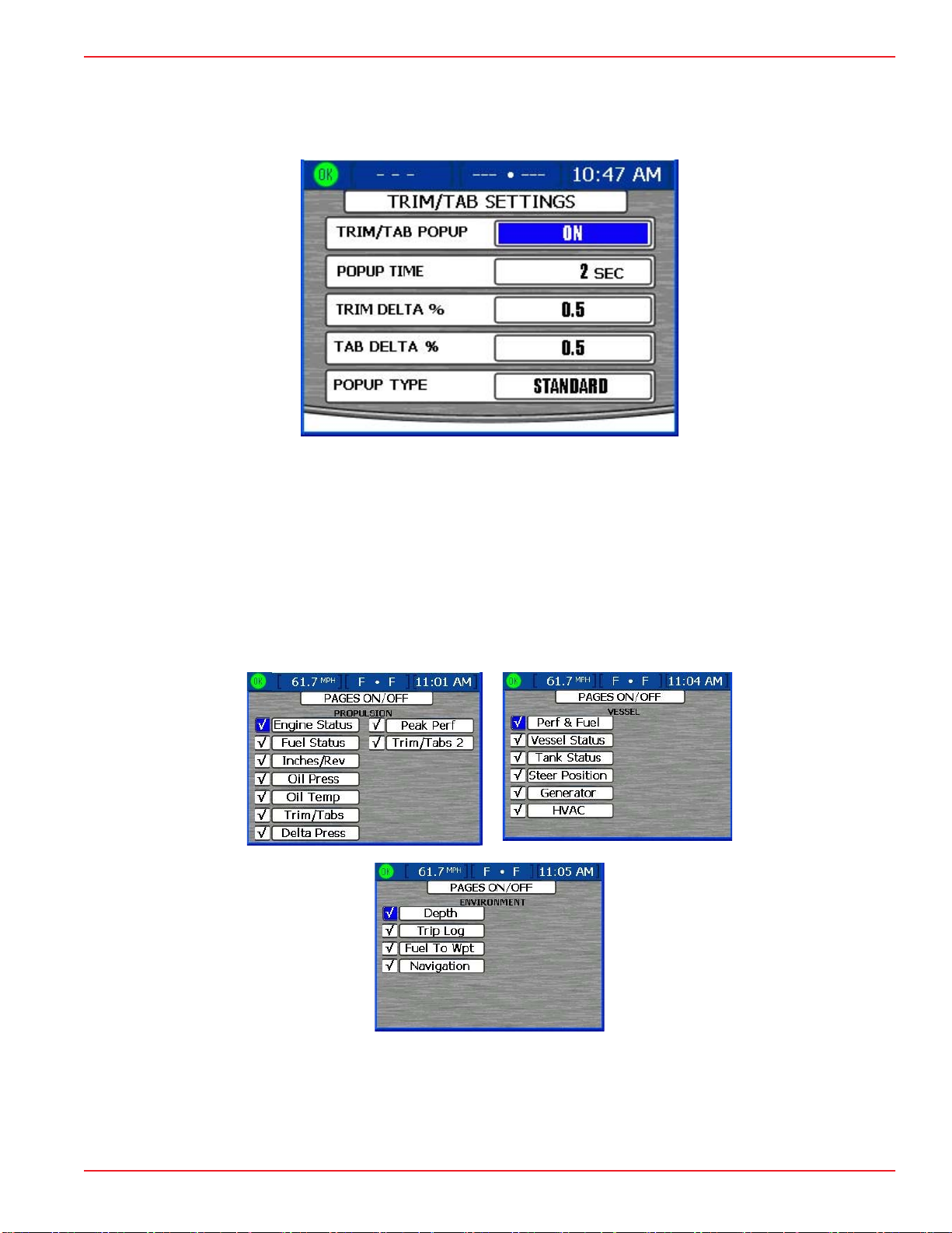
Trim/Tab Pop‑Up (Settings)........................102
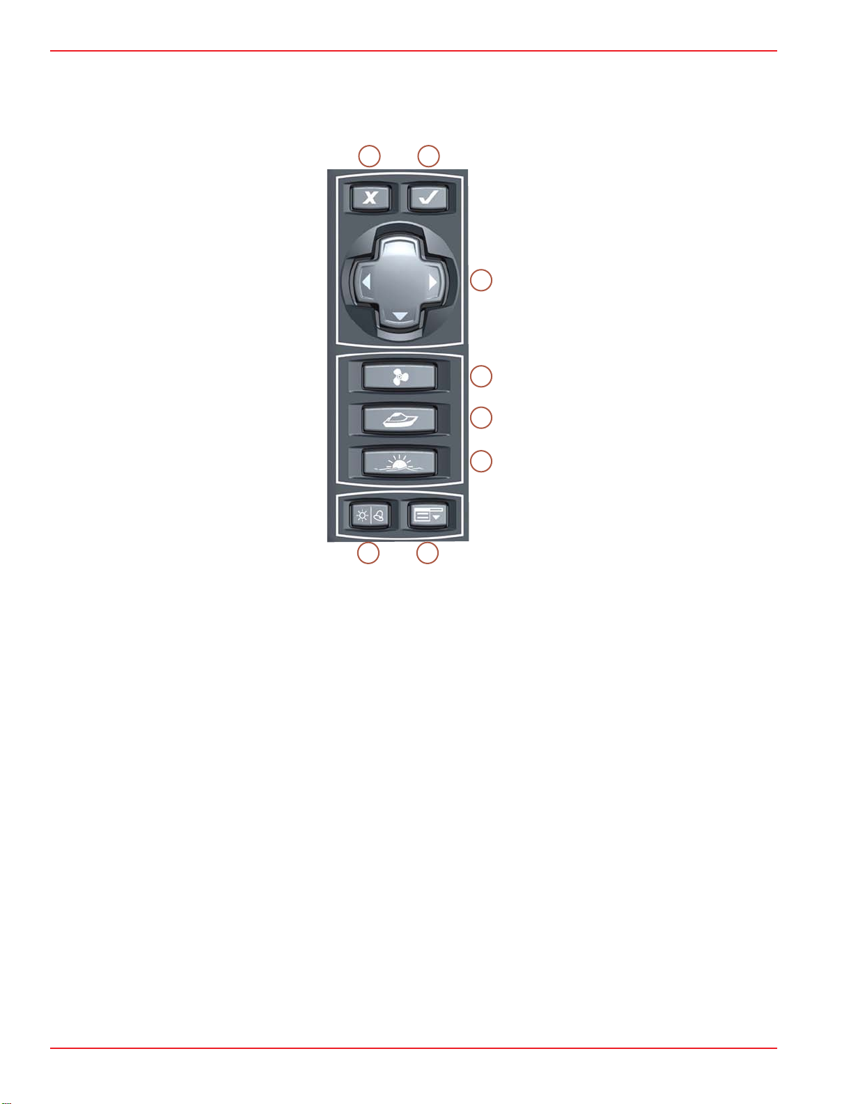
Hot Keys......................................................104
Pages On/Off..............................................107
Alarms................................................................109
Alarms Menu Options..................................109
VesselView Warning Horn Strategy............109
Active Alarms..............................................110
Fault Icons................................................111
Viewing Active Alarms..............................112
Viewing Alarm Details...............................113
Alarm History...............................................113
Alarm History Details................................114
Clearing Alarm History..............................115
System Information............................................116
System Information Menu Options..............116
Software Info...............................................116
Hardware Info..............................................117
Tech...................................................................117
Tech Menu Options.....................................117
RPM Bands.................................................117
Section 5 - Propulsion Menu
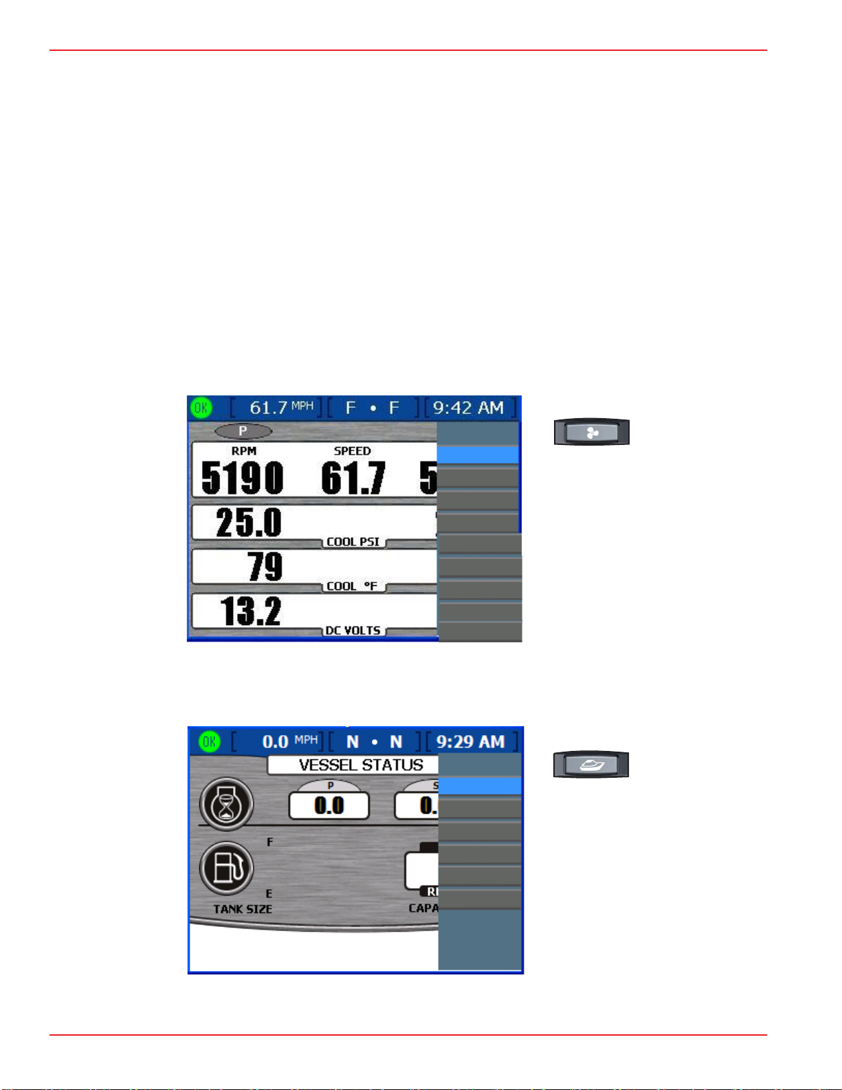
Using Propulsion Screens..................................120
Viewing Engine Status...................................120
Viewing Fuel Status.......................................121
Resetting Fuel Used.................................122
Viewing Inches/Rev.......................................122
Viewing Oil Pressure.....................................123
Viewing Oil Temperature...............................124
Viewing Trim/Tabs.........................................125
Viewing Delta Pressure.................................125
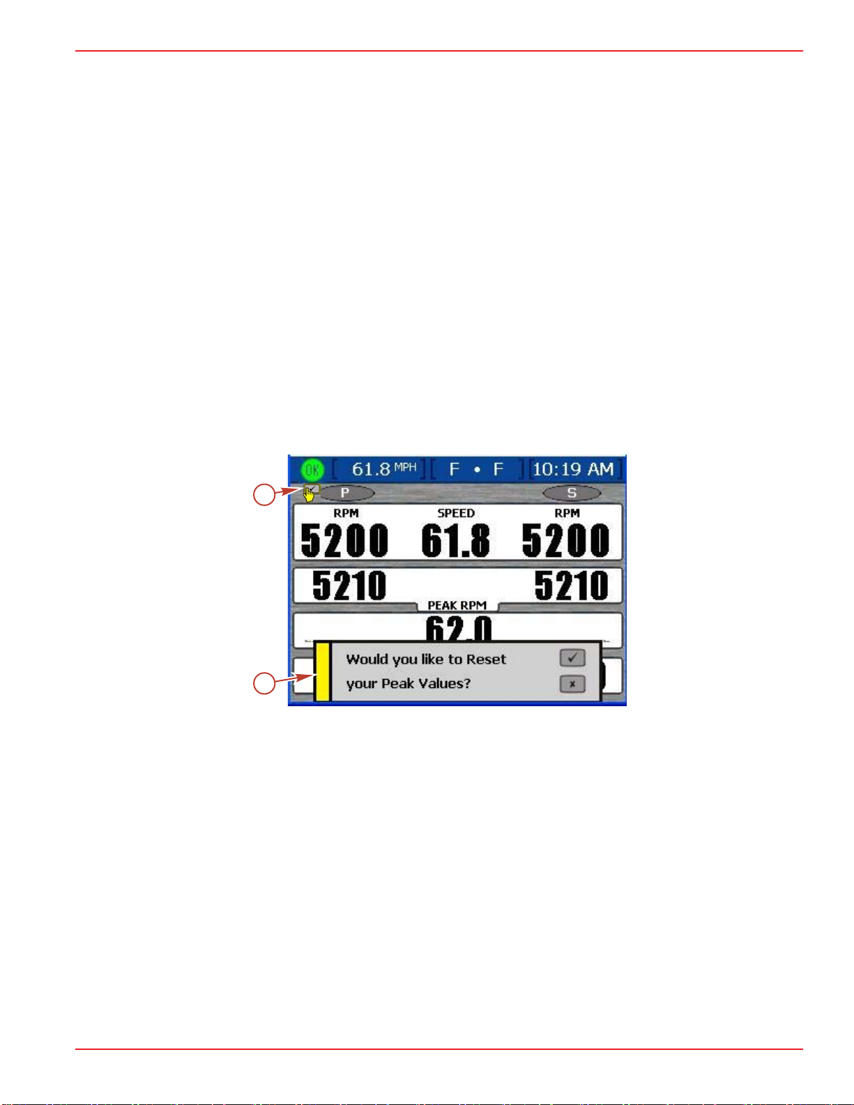
Viewing Peak Performance...........................127
Resetting Peak Values..............................128
Viewing Trim/Tabs 2......................................128
Section 6 - Vessel Menu
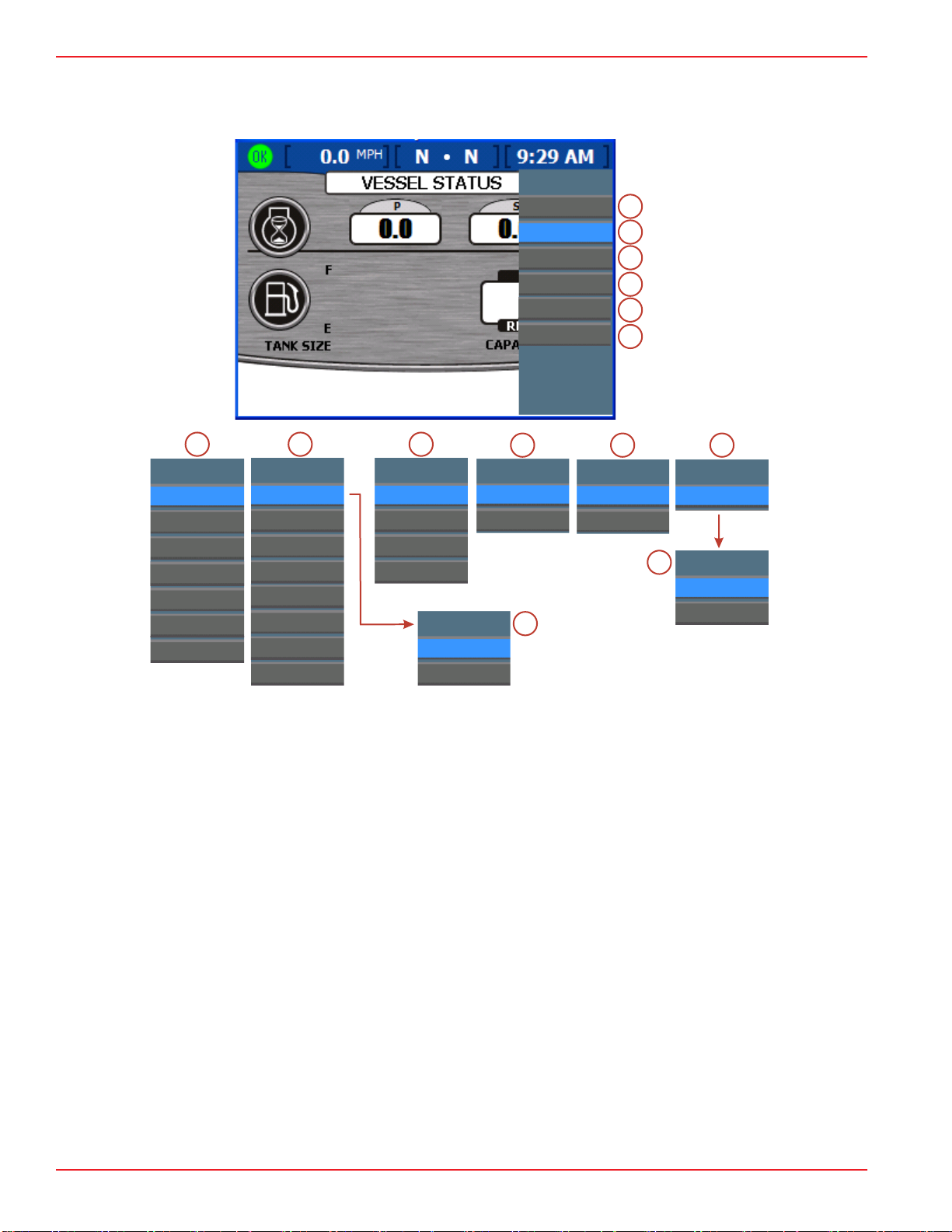
Using Vessel Screens........................................132
Viewing Performance and Fuel.....................133
Resetting Total Fuel Used........................134
Checking Vessel Status.................................134
Checking Tank Status....................................135
Viewing Steering Position..............................136
Viewing Generator Data................................137
Section 7 - Environment and Navigation Menu
Using Environment and Navigation Screens......140
Viewing Depth and Water Temperature........141
Setting Depth Alerts..................................141
Viewing Trip Log Information.........................143
Resetting Trip Log Amounts.....................144
Viewing Fuel to Waypoint Data......................144
Viewing Navigation Data................................146

90-8M8022154 APRIL 2008 Page iii
Section 8 - Installation and Wiring
Cutting the Instrument Panel...............................148
Preparing the Mounting Location.................148
Cutting the Panel..........................................148
Securing VesselView to the Instrument
Panel............................................................149
VesselView Bezel Removal..........................149
DTS Wiring Guidelines........................................150
Wiring Guidelines for Electrical Boat Accessories
........................................................................150
Harness Installation Guidelines......................150
VesselView Harness Connection for SmartCraft
Version 07 and Up...............................................151
Wiring Connections for SmartCraft Version 07....152
VesselView Harness and Adapter..................152
MerCruiser and Outboard Applications ‑ Single
Engine ............................................................154
MerCruiser and Outboard Applications ‑ Dual
Engine.............................................................156
MerCruiser and Outboard Applications ‑ Triple
Engine.............................................................160
MerCruiser and Outboard Applications ‑ Quad
Engine.............................................................164
Mercury Racing Sterndrive Applications.........167
Installing the Ambient Air Temperature Sensor...168
Installing the NMEA 0183 Adapter Harness........169
NMEA 0183 Connector...................................170
Calibration Logs...................................................172
Tank Calibration Reference Sample Log........172
Tank Calibration Reference Log.....................174
Manual Tank Calibration Screen Log.............175
VesselView Template Cutout..............................175
Section 9 - Glossary of Terms and Service Contact Information
VesselView Systems Terminology......................180 Mercury Marine Service Offices..........................182

Page iv 90-8M8022154 APRIL 2008

Section 1 - Getting Started
90-8M8022154 APRIL 2008 Page 1
Section 1 - Getting Started
Table of Contents
VesselView Specifications.................................... 2
VesselView Race Edition Components and Part
Numbers ......................................................... 2
Overview............................................................... 2
Keypad Functions................................................. 4
X Button ......................................................... 4
Check Button .................................................. 4
Arrow Trackpad .............................................. 4
Propulsion, Vessel, and Environment Buttons
....................................................................... 5
Brightness and Alarm Button ......................... 5
Menu Button ................................................... 5
Turning the VesselView Unit On or Off................. 5
Restarting VesselView.......................................... 5
Cleanliness and Care of Product.......................... 5
Using the Menu Panel.......................................... 6
Navigating Through the Screens .................... 8
Using Dialog Boxes and Pop-Up Windows........... 9
Dialog Boxes .................................................. 9
Pop-Up Window Preferences ......................... 9
Alarm Details Pop-Up Window ................. 9
Trim/Tab Pop-Up Window Settings ........ 10
Page/Screen Organization.................................. 11
Screen Brightness.............................................. 12
Using Brightness/Alarm Button .................... 12
Using the "Clock/Light" Menu Option ........... 12
Status Bar........................................................... 13
Fault Icons .................................................... 14
Fuel Alarms ............................................ 15
Saving Settings................................................... 16
1

Section 1 - Getting Started
Page 2 90-8M8022154 APRIL 2008
VesselView Specifications
Component Specification
Power / Digital Communications 2‑24 Pin VesselView Female Harness Connectors
USB Port
V1.1 or V2.0 (That is stated to be backwards compatible to
V1.1)
IMPORTANT: VesselView unit will not recognize memory sticks
that are only V2.0 compatible.
Ethernet Port For future option.
VesselView Unit Dimensions
Case 180.5 mm x 112.0 mm
(7.1 in. x 4.4 in.)
Bezel 197.8 mm x 132.5 mm
(7.8 in. x 5.2 in.)
Net Weight (VesselView Unit without Harness) 0.82 kg (1.8 lb)
VesselView Race Edition Components and Part Numbers
IMPORTANT: A SystemView harness is NOT compatible with VesselView. VesselView
must only be installed using the harness contained in the VesselView kit.
VesselView Race Edition Kits
Harness/Kit/Component Part Number
Service Kit: Includes only the display unit. 79‑898277K14
Kit Without GPS: Includes display, vessel harness assy., GPS harness assy., VesselView
adapter harness, and USB extension harness with dash mount plug. 79‑898277K15
Kit With GPS: Includes K15, GPS antenna, and CAN P extension harness. 79‑898277K16
VesselView Race Edition Kit Components
Harness/Kit/Component Part Number
Vessel Harness Assembly 84‑898273T01
VesselView Adapter Harness (Not required if a Mercury Racing Sterndrive Rigging Kit is
installed on vessel.) 84‑889278T01
GPS Antenna 879172T64
VesselView NEMA 0183 Adapter Harness Assembly 84‑899751T01
CAN P GPS Harness 84‑879171T23
Temperature Sensor Assembly 56‑820386A76
USB Extension Harness With Dash Mount Plug 84‑8M2100083
Overview
VesselView Race Edition is a comprehensive vessel information center. VesselView Race
Edition displays vital information for up to three engines at one time and link gauge support
for a fourth engine. It continuously monitors and reports basic operating data, as well as
detailed information such as sea water temperature and depth, trim status, vessel speed
and steering angle, and the status of fuel, oil, water, and waste tanks.
VesselView Race Edition can be fully integrated with a vessels global positioning system
(GPS) or other NMEA‑compatible device to provide navigation, speed, and
fuel‑to‑destination information.

Section 1 - Getting Started
90-8M8022154 APRIL 2008 Page 3
The VesselView unit is equipped with a USB port that enables configuration settings to be
saved to, or imported from, a USB memory stick.
32711
a
b
c
VesselView Race Edition display screens are grouped into three categories:
a - Propulsion button enables you to
quickly access the propulsion
screens that are related to
propulsion, trim, tabs, and engine
performance.
b - Vessel button enables you to
quickly access the vessel screens
that are related to fuel use, tank
levels, and other items such as
generators, heating and air
conditioning systems, and
ventilation.
c - Environment and Navigation
button enables you to quickly
access the environment and
navigation screens that are related
to depth, navigation, and GPS.

Section 1 - Getting Started
Page 4 90-8M8022154 APRIL 2008
Keypad Functions
Mounted on the VesselView unit are seven buttons and an arrow trackpad for easy
navigation through screens and pages.
a
b
c
d
e
f
g
h
25354
a - X button
b - Check button
c - Arrow trackpad
d - Propulsion button
e - Vessel button
f - Environment and navigation button
g - Brightness and alarm button
h - Menu button
X Button
•Enables a full shut down of VesselView when held down while the engine key
switch is turned off.
• Deactivates or cancels the highlighted selection.
• Performs other functions as described in the on‑screen prompts.
• Closes the menu panel.
Check Button
• Activates or confirms the highlighted selection.
• Accesses functions within pages.
• Performs other functions as described in the on‑screen prompts.
Arrow Trackpad
• Operates the up, down, and side‑to‑side movement of the VesselView cursor to
navigate through the various screens and function prompts.
• Toggles through the available category screens.

Section 1 - Getting Started
90-8M8022154 APRIL 2008 Page 5
• Performs other functions as described in the on‑screen prompts.
Propulsion, Vessel, and Environment Buttons
• Opens the last screen viewed in the particular category.
• Toggles through the available category screens.
Brightness and Alarm Button
• Opens the screen brightness control for brightness adjustment of the VesselView
screen (when no faults are present).
• Enables quick access to the "ACTIVE ALARMS" screen where active faults and their
details are shown (when faults are present).
Menu Button
• Opens the menu panel of the active category.
• Toggles between the "Main" menu and the menu of the active category.
Turning the VesselView Unit On or Off
The VesselView unit automatically turns on when the key switch for any engine connected
to the unit is turned to the "RUN" position.
VesselView enters suspend mode 48 hours after the key switches for all engines connected
to the VesselView unit are turned to the "OFF" position. When any engine key switch is
turned to the "RUN" position again, VesselView quickly displays the last active screen.
To shut down the VesselView unit completely for storage or to save configuration session
changes, press the X button while turning the engine key switches to the "OFF" position.
Do not interrupt power to the unit while it displays the powering off screen. If power is
interrupted while VesselView is shutting down, changes made during that session may be
lost. When any engine key switch is turned to the "RUN" position again, VesselView
displays the last active screen after it completes the boot sequence.
IMPORTANT: If the battery switches are turned off, the VesselView unit will shut down
immediately, while this will not damage the unit, all session configuration changes made
since the last configuration save will be lost.
NOTE: When not in use, cover the VesselView unit with its protective cover to prevent the
screen from becoming damaged.
During the initial startup sequence for VesselView, a setup wizard screen appears,
prompting you to enter the initial setup for the unit. If this happens, follow the procedures in
Section 2 - Setup and Calibration. This setup wizard does not return once completed
unless a factory reset is performed.
Restarting VesselView
At any time you can restart VesselView without the loss of any information or configuration
changes.
To restart VesselView, press and hold the X button and the check button at the same time
until the system restarts. VesselView will display the last active screen after it completes
the boot up cycle.
Cleanliness and Care of Product
Clean the VesselView screen with water and a soft cloth. Do not use detergents. When not
in use, cover the VesselView unit with its protective cover to prevent the screen from
becoming damaged.

Section 1 - Getting Started
Page 6 90-8M8022154 APRIL 2008
Using the Menu Panel
Menus enable you to quickly access the same screens available through the propulsion,
vessel, and environment and navigation buttons; as well as the calibration, settings,
settings 2, alarms, system, and RPM bands information screens only available in the menu
panel. To use the menu panel, follow these steps:
1. Press the menu button. The menu panel specific to the currently open screen category
("Propulsion", "Vessel", "Env/Nav") appears.
2. Press a button to open the appropriate menu panel.
a. To see the available propulsion screens, press the propulsion button and then the
menu button. The "Propulsion" menu panel appears.
IMPORTANT: The available VesselView menu options may display differently than those
listed in the pictures; menu options depend on the engine type, if tabs are a part of the
vessel configuration, and if screens have been manually turned on or off. Those screens
turned off in the "Pages On/Off" menu option will also not appear in their respective menu.
If you suspect you are missing a screen, refer to Section 4 ‑ Pages On/Off and review the
list to ensure all screens are turned on.
Propulsion
Engine Status
Fuel Status
Inches/Rev
Oil Press
Trim/Tabs
Delta Press
32631
Oil Temp
Peak Perf
Trim/Tabs 2
Propulsion Menu Panel
b. To see the available vessel screens, press the vessel button and then the menu
button. The "Vessel" menu panel appears.
Vessel
Perf & Fuel
Vessel Status
Speed
Tank Status
Generator
Steer Position
32632
Vessel Menu Panel

Section 1 - Getting Started
90-8M8022154 APRIL 2008 Page 7
c. To see the available environment and navigation screens, press the environment
and navigation button and then the menu button. The "Env/Nav" menu panel
appears.
Env Nav
Depth
Trip Log
Navigation
Fuel To Wpt
/
32710
Environment/Navigation Menu Panel

Section 1 - Getting Started
Page 8 90-8M8022154 APRIL 2008
d. To see the available main screens, with the menu panel open in any of the
categories, press the menu button. The "Main" menu panel appears. When the
menu button is pressed again VesselView toggles back to the category menu.
Screen Opt.
Status bar
Steering
Main
Calibrate
Settings
Settings 2
Alarms
Alarms
Alarm History
Active Alarms
System Info
Hardware Info
Software Info
33328
a
b
c
d
e
d
b
a
System Info
Tech
Calibrate
Tank
Tabs
Trim
Configuration
Factory Reset
Save Configs
e
f
Settings 2
Tabs
Trim/Tab Popup
Hot Keys
Pages On/Off
c
Tech
RPM Bands
f
Settings
Screen Options
Clock/Light
Preferences
Sensors
Warnings
Units
Units 2
Offsets
Load Configs
RPM Bands
STBD History
PORT History
g
h
a - Calibration menu
b - Settings menu
c - Settings 2 menu
d - Alarms menu
e - System Info menu
f - Tech menu
g - Screen Options menu
h - RPM Bands menu
3. Use the arrow trackpad to choose a menu item.
4. Press the check button to confirm your choice.
Navigating Through the Screens
There are four distinct ways to navigate through the various VesselView screens.
1. By pressing the propulsion button, vessel button, or the environment and navigation
button. The available screens in each category can be adjusted using the Pages On/
Off screen. Refer to Section 4 - Pages On/Off for the description of how to select
specific screens to appear in each category.
2. By pressing the left or right arrow on the arrow trackpad. This will toggle through the
available screens of the selected category.

Section 1 - Getting Started
90-8M8022154 APRIL 2008 Page 9
3. By pressing the menu button. The available screens in each category will appear in the
menu list of data screens. The menu list of data screens is influenced by the "Pages
On/Off" screen. The data screens turned off will not appear in the menu list.
4. By pressing the down or up arrow on the arrow trackpad. This will jump to a predefined
hot key screen that is assigned to that arrow function. Refer to Section 4 - Hot Keys
for the description of how to assign hot keys.
Using Dialog Boxes and Pop‑Up Windows
Dialog boxes appear within screens to enable access to controls, functions, changes to
settings, or calibrations, specific to that screen. Pop‑up windows are informational windows
that show alarms or a status of something like the tab position or propulsion unit trim
position. Pop‑up windows will appear on any screen in VesselView as a pop‑up window
and will remain open for a short duration of time or, as is the case of the "ALARMS
DETAILS" pop‑up window, the X button is pressed.
Dialog Boxes
The control icon appears in the upper left corner of any screen that includes a dialog box
for access to controls and screen functions. The control icon disappears about 3 seconds
after each screen is loaded. To open a dialog box from one of these screens, press the
check button. To close the dialog box, press the X button.
33079
a
b
a - Control icon b - Dialog box
Pop‑Up Window Preferences
There are two pop‑up windows that can be adjusted to appear once limits are reached and/
or off so they do not appear; the "ALARM DETAILS" pop‑up and the, depending on the
vessel configuration, "TRIM" or "TRIM/TAB" pop‑up.
ALARM DETAILS POP-UP WINDOW
Alarms and faults will display on the "ALARM DETAILS" pop‑up window to notify you of a
condition requiring your attention. Refer to Section 4 - Alarms for more information about
alarms. To close the "ALARM DETAILS" pop‑up window press the X button.
To access the "ALARM DETAILS" preferences pop‑up, press the menu button until the
"Main" menu appears, then select "Settings" > "Preferences". Press the down or up arrow
on the arrow trackpad to highlight the "POP‑UP WARNINGS" preference. Pressing the left
or right arrow on the arrow trackpad will toggle between "YES" or "NO".

Section 1 - Getting Started
Page 10 90-8M8022154 APRIL 2008
If no is selected the faults/warnings will not appear as a pop‑up on the screen but the status
bar will still display the current faults/warnings. Refer to Section 1 - Status Bar for further
information.
33075
TRIM/TAB POP-UP WINDOW SETTINGS
The trim/tab pop‑up window can be modified to be "On" or "Off", its length of time that the
pop‑up remains open as well the quality of the pop‑up detail ("Standard" or "High
Resolution"). To access the "TRIM/TAB SETTINGS" screen, press the menu button until
the "Main" menu appears, then select "Settings 2" > "Trim/Tab Popup".
33092
STANDARD HIGH RESOLUTION

Section 1 - Getting Started
90-8M8022154 APRIL 2008 Page 11
Depending on the vessel configuration, the pop‑up will only display components connected
to the VesselView unit. If both trim and tabs exist on the vessel, and are connected to the
VesselView unit, the "TRIM/TAB" pop‑up will display both the trim chart and the tab chart.
Whereas, if only trim is connected, only the trim chart will display in the pop‑up.
33073
To change the settings for the trim/tab pop‑up window, refer to Section 4 - Trim/Tab
Pop-Up (Settings).
Page/Screen Organization
VesselView enables a user to specify exactly what screens, in each of the three categories,
they want to have visible for quick access. Each category; propulsion, vessel, or
environment and navigation, have a variety of default screen layouts with different
information on each. Refer to Section 4 - Pages On/Off to learn how to select screens for
each category.
32885

Section 1 - Getting Started
Page 12 90-8M8022154 APRIL 2008
Screen Brightness
There are two methods to adjust the brightness; with the "Main" > "Settings" > "Clock/Light"
menu option or with the brightness/alarm button. The screen brightness can be adjusted
using the brightness/alarm button while in any VesselView display screen as long as there
is not an active fault in the system. If an active fault exists, the brightness/alarm button will
first go to the "Active Alarms" screen. Press the brightness/alarm button a second time and
the "Screen Brightness" control will appear.
26950
Screen brightness control
The screen brightness control enables you to adjust the brightness of the screen on a scale
of 0 to 15. To adjust screen brightness, use the following steps:
Using Brightness/Alarm Button
1. Press the brightness/alarm button. The "Screen Brightness" control will appear.
2. Use the left or right arrow on the arrow trackpad to adjust screen brightness. The right
arrow increases brightness. The left arrow decreases brightness.
3. Press the brightness/alarm button to exit.
NOTE: Upon completing any change/customization to VesselView it is necessary to save
your session. Refer to
Section 1 - Saving Settings
. It is recommended that all changes
be made before saving the session.
Using the "Clock/Light" Menu Option
Menu path: "Main" > "Settings" > "Clock/Light". Refer to Section 4 - Clock/Light to learn
about the other adjustments in this screen.
a
b
c
d
27135
a - Hours
b - Minutes
c - 12/24 Hour Display
d - Brightness

Section 1 - Getting Started
90-8M8022154 APRIL 2008 Page 13
1. Upon entering the "CLOCK/BRIGHTNESS" screen, the "HOURS (0‑23)" field will be
highlighted in blue.
2. Press the down arrow on the arrow trackpad to proceed to the "BRIGHTNESS" field.
3. Press the left or right arrow on the arrow trackpad to adjust screen brightness. The right
arrow increases brightness and the left arrow decreases brightness.
4. Once you have selected the preferred brightness setting, press the check button to
save the session.
NOTE: Upon completing any change/customization to VesselView a blue pop‑up message
will appear as a reminder to save your session. Refer to
Section 1 - Saving Settings
. To
save time, it is recommended that all session changes be saved before holding
X
button
while keying ALL engines off.
Status Bar
VesselView displays important information in the status bar at the top of each screen. The
status bar displays up to four different icons and messages. Notices of conditions that may
need attention (such as warnings, fuel level alerts, and faults) appear as an icon on the left
side of the status bar with a short description of the fault. The fault text will temporarily
replace the status bar icons until the fault is cleared. If more than one fault has occurred,
the faults will appear one after the other in the sequence they occurred. To clear a fault
message from the status bar, after a fault has been corrected, press the X button. Refer to
Section 4 - Alarms for more information about alarms and fault codes. Refer to Section
1 - Using Dialog Boxes and Pop-Up Windows to learn how to view the "ALARM
DETAILS" pop‑up window.
33069
Table of contents
Popular Control Unit manuals by other brands

Texas Instruments
Texas Instruments Piccolo F280049C user guide

NI
NI PXIe-5673E Getting started guide

SIMCom Wireless Solutions
SIMCom Wireless Solutions SIM7600A-H user manual

Allen-Bradley
Allen-Bradley XM-124 user manual

Conti+
Conti+ Lino WV10 Installation & user manual

Leonard
Leonard TM-186-30015050-PRV INSTALLATION ADJUSTMENT SERVICE

OMAL S.p.A
OMAL S.p.A 424 Series Maintenance and spare parts

SMC Networks
SMC Networks S0700 Installation and maintenance manual

Bosch
Bosch KTS 5 Series Original instructions

DSC
DSC PC5928 quick start guide

ESMI
ESMI FX-CLC installation instructions

Watts
Watts Ames 986GD Installation, operation and maintenance manual