Mercury Security MR62e User manual
Mercury Security © 2019 MR62e DOC 10107-0057 REV 1.02 Page 1
www.mercury-security.com
2355 MIRA MAR AVE. LONG BEACH, CA 90815-1755, (562)986-9105 FAX (562) 986-9205
MR62e OSDP Reader Interface
Installation and Specifications
1. General:
The MR62e OSDP reader interface provides a network connected interface to control two physical barriers
using OSDP readers and provides a solution for the OEM integrator for interfacing to OSDP readers and
door hardware. The on-board Ethernet with PoE/PoE+ support enables easy installation. The MR61e
supports up to four OSDP readers configured as paired or alternate readers.
Note: For UL, the Power Sourcing Equipment (PSE) such as a PoE/PoE+ enabled network switch and/or
PoE/PoE+ power injectors must be UL Listed under UL294B.
One serial 2-wire RS-485 communication port is available that can accommodate up to four OSDP
readers. Four Form-C relay outputs may be used for door strike control or alarm signaling. The relay
contacts are rated at 2 A @ 30 Vdc, resistive and are in a dry contact configuration. Six inputs are provided
that may be used for monitoring the door contacts, exit push buttons, and alarm contacts. Input circuits
can be configured as unsupervised or supervised. The MR62e requires PoE, PoE+ or local 12 Vdc for
power. The MR62e may be mounted in a 3-gang switch box; a mounting plate is supplied with the unit or
be mounted in an enclosure; the supplied mounting plate has mounting holes that match the MR50
mounting footprint.
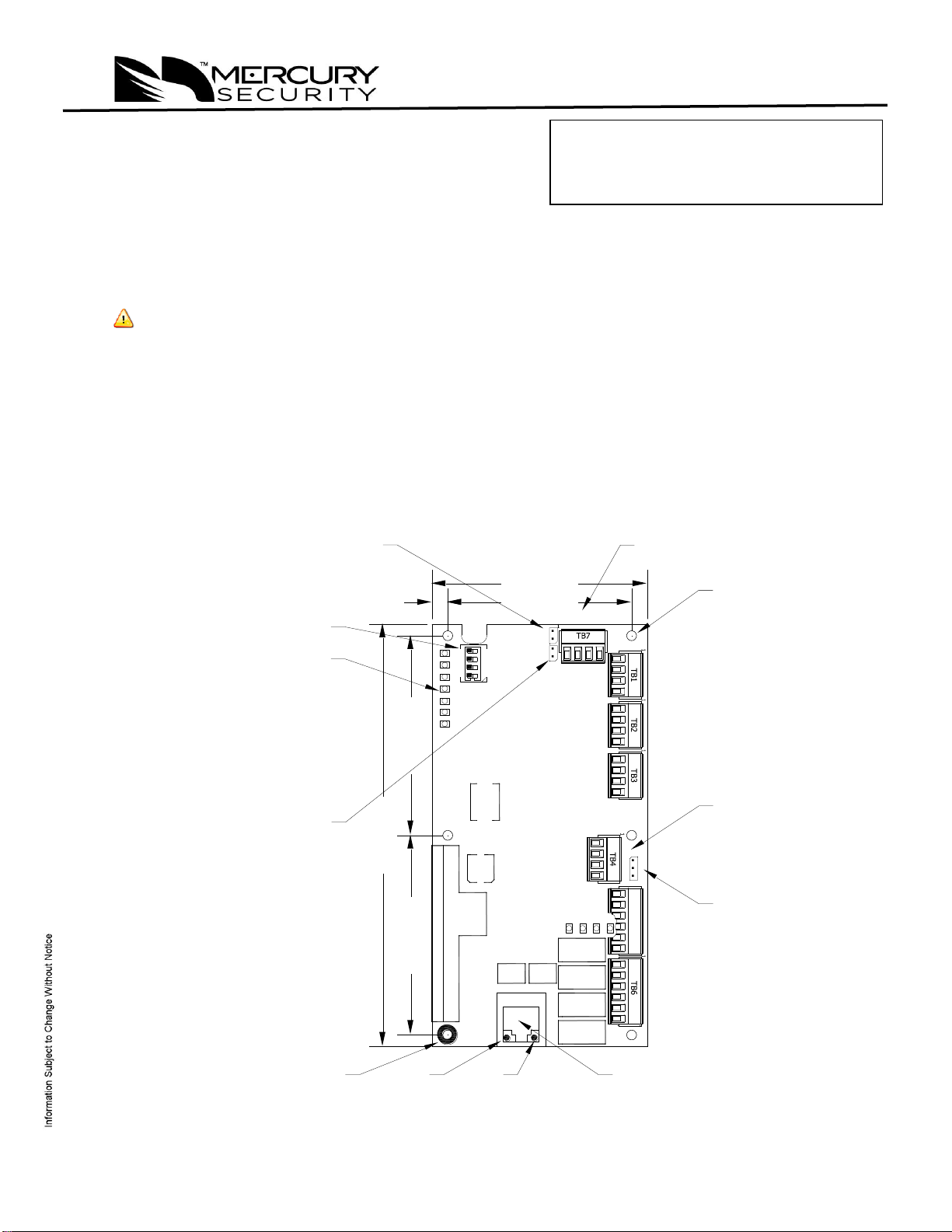
2. MR62e Hardware:
MR62e Layout
TB5
1
IN1 IN2 IN3 IN4 IN5 IN6
VO GND
VIN
GND
VIN POE
J5
NO NC
2-C
NO
NC
1-C NO NC
4-C
NO
NC
3-C
K1 K2 K3 K4
K4
K3
K2
K1
RVOGND TR- TR+
J3 J4
J1
10519-0000-F, REV-A
7654321
2
3
41
S1
ON
|
|
V
INPUTS
RELAYS
J5: INPUT
POWER
SELECT
12 Vdc IN &
AUX POWER
OUTPUT
2.55 [64.77]
2.55 [64.77]
5.4 [137.16]
STATUS
LEDs
2.35 [59.69]
2.75 [69.85]
.2 [5.08]
S1: DIP
SWITCH
J3: TAMPER
SWITCH
TO OSDP
READERS
LINK
(GREEN)
SPEED
(YELLOW)
J4: TIA-485
TERMINATION
JUMPER
Ø.125 [3.18]
6 PLACES
EARTH
GROUND
J1: ETHERNET RJ45
CONNECTOR
This device complies with part 15 of the FCC Rules. Operation
is subject to the following two conditions: (1) This device may
not cause harmful interference, and (2) this device must
accept any interference received, including interference that
may cause undesired operation.

Mercury Security © 2019 MR62e DOC 10107-0057 REV 1.02 Page 2
3. MR62e Terminal Blocks and Jumpers/Jacks:
MR-51E CONNECTIONS
TB1-1
IN1
Input 1
TB1-2
IN1
TB1-3
IN2
Input 2
TB1-4
IN2
TB2-1
IN3
Input 3
TB2-2
IN3
TB2-3
IN4
Input 4
TB2-4
IN4
TB3-1
IN5
Input 5
TB3-2
IN5
TB3-3
IN6
Input 6
TB3-4
IN6
TB4-1
VO
Auxiliary Power Output –12 Vdc
TB4-2
GND
Auxiliary Power Output Ground
TB4-3
VIN
Input Power –12 Vdc (from local power supply)
TB4-4
GND
Input Power Ground
TB5-1
NO
Relay K1 –Normally Open Contact
TB5-2
1-C
Relay K1 –Common Contact
TB5-3
NC
Relay K1 –Normally Closed Contact
TB5-4
NO
Relay K2 –Normally Open Contact
TB5-5
2-C
Relay K2 –Common Contact
TB5-6
NC
Relay K2 –Normally Closed Contact
TB6-1
NO
Relay K3 –Normally Open Contact
TB6-2
3-C
Relay K3 –Common Contact
TB6-3
NC
Relay K3 –Normally Closed Contact
TB6-4
NO
Relay K4 –Normally Open Contact
TB6-5
4-C
Relay K4 –Common Contact
TB6-6
NC
Relay K4 –Normally Closed Contact
TB7-1
GND
Reader Power Ground
TB7-2
TR-
2-Wire RS-485 TR- (B) See Note 1 below
TB7-3
TR+
2-Wire RS-485 TR+ (A) See Note 1 below
TB7-4
RVO
12 Vdc Reader Power Output
Note 1: Terms A & B are from the RS-485 standard
Jumpers:
JUMPER
SET AT
DESCRIPTION
J1
N/A
Ethernet Connection with PoE/POE+ support
J2
N/A
Factory Use Only
J3
N/A
Tamper Switch (normally open contact) See section 14.
J4
N/A
RS-485 Termination, install only if the MR62e is at the
end of the communication bus
J5
PoE
MR62e powered from the Ethernet connection
VIN
MR62e powered from an external 12 Vdc power source
connected to TB4-3 (VIN), TB4-4 (GND)
J6 –J13
N/A
Factory Use Only
Mercury Security © 2019 MR62e DOC 10107-0057 REV 1.02 Page 3
4. DIP Switches:
The four switches on S1 DIP switch are used to configure the operating mode of the MR62e.
DIP switches are read on power-up except where noted.
1
2
3
4
Definitions
OFF
OFF
OFF
OFF
Normal operating mode.
ON
X
OFF
OFF
After initialization, enable default User Name (admin) and
Password (password). The switch is read on the fly, no need to
reboot. See IT Security section for additional information
OFF
ON
OFF
OFF
Use factory default communication parameters.
ON
ON
OFF
OFF
Use OEM default communication parameters. Contact system
manufacture for details. See Bulk Erase below.
ON
ON
OFF
OFF
Bulk Erase prompt mode at power up. See Bulk Erase section.
All other switch settings are unassigned and reserved for future use. X = don’t care.
Factory Default Communication Parameters:
Network: static IP address: 192.168.0.251
Subnet Mask: 255.255.0.0
Default Gateway: 192.168.0.1
5. Bulk Erase:
The bulk erase function can be used for the following purposes:
Erase all configuration, sets MR62e to OEM setting (sanitize board).
Restore to OEM default parameters.
Bulk Erase Steps: Do not remove power during steps 4-6.
1. Set S1 DIP switches to: 1 & 2 "ON", 3 & 4 "OFF".
2. Apply power to the MR62e.
3. Watch for LEDs 1 & 2 and 3 & 4 to alternately flash at a 0.5 second rate.
4. Within 10 seconds from applying power, change switches 1 or 2 to "OFF". If these switches are not
changed, the MR62e will power up using the OEM default communication parameters.
5. LEDs 1 and 2 alternately flash at a 0.5 second rate while the memory is being erased.
6. Once the memory is eased, LED 1 will be on for about 3 seconds, then the MR62e will reboot.
6. Input Power:
The MR62e is powered by one of two ways (jumper selected, J5):
Power is supplied via the Ethernet connection using PoE or PoE+.
Local 12 Vdc power supply, TB4-3 (VIN), TB4-4 (GND).
7. Communication Wiring:
Communication between the EP controller and the MR62e is Ethernet (10Base T/100Base-TX).
It is not recommended to connect the MR62e to a public intranet.
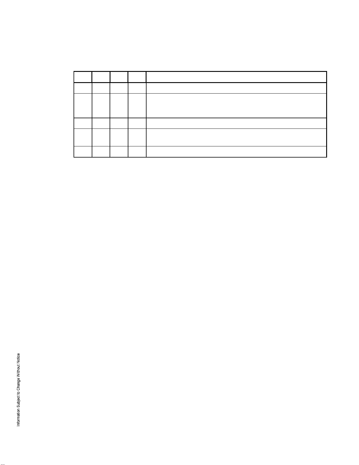
8. OSDP Reader Wiring:
TB7 has connections for the 2-wire RS-485 OSDP communication bus and 12 Vdc to power the OSDP
readers. Up to four OSDP readers are supported on the MR62e. This 12 Vdc output is limited to .5 A.
maximum. The OSDP reader wiring diagram below shows the use of a 2-pair cable for data and power.
If this cable cannot support the voltage/current requirements, a 1-pair cable of sufficient gauge must be
used for power. See specification section.

Mercury Security © 2019 MR62e DOC 10107-0057 REV 1.02 Page 4
The RS-485 termination jumper, J4, is only installed if the MR62e is at one end of the communication
bus. Only devices at each end of the communication bus are terminated, never install termination to
more than two devices on the communication bus.
When powering any remote device(s) by the MR62e, care must be taken not to exceed the maximum
current available. Cable gauge must also be evaluated. See specifications section for details.
Typical OSDP Reader Wiring
9. Input Circuit Wiring:
Typically, these inputs are used to monitor door position, request to exit, or alarm contacts. Input circuits
can be configured as unsupervised or supervised. When unsupervised, reporting consists of only the
open or closed states.
When configured as supervised, the input circuit will report not only open and closed, but also open circuit,
shorted, grounded*, and foreign voltage*. A supervised input circuit requires two resistors be added to the
circuit to facilitate proper reporting. The standard supervised circuit requires 1K Ohm, 1% resistors and
should be located as close to the sensor as possible. Custom end of line (EOL) resistances may be
configured via the host software.
*Grounded and foreign voltage states are not a requirement of UL 294 and therefore not verified by UL.
The input circuit wiring configurations shown are supported but may not be typical:
TR+ (A)
TR+ (A)
RVO
TR- (B)
GND
TR- (B)
GND
TB7
1
12 V
J3 J4
J4: INSTALL ONLY IF MR62e IS AT THE
END OF THE COMMUNICATION BUS
TR+ (A)
GND
TR- (B)
12 V
TR+ (A)
GND
TR- (B)
12 V
TR+ (A)
GND
TR- (B)
12 V
SHIELD: CONNECT TO
EARTH GROUND,
ONE END ONLY!
1K,1%
1K,1%
1K,1%
1K,1%
Standard Supervised Circuit,
Normally Closed Contact
Standard Supervised Circuit,
Normally Open Contact
Unsupervised Circuit,
Normally Open Contact
Unsupervised Circuit,
Normally Closed Contact
TB2
IN4
IN2
IN3
1
IN1
TB1
1
}

Mercury Security © 2019 MR62e DOC 10107-0057 REV 1.02 Page 5
10. Relay Circuit Wiring:
Four Form-C contact relays are provided for controlling door lock mechanisms or alarm signaling. The
relay contacts are rated at 2 A @ 30 Vdc, resistive and are in a dry contact configuration. When you are
controlling the delivery of power to the door strike, the Normally Open and Common poles are used. When
momentarily removing power to unlock the door, as with a mag lock, the Normally Closed and Common
poles are used. Check with local building codes for proper egress door installation.
Door lock mechanisms can generate feedback to the relay circuit that can cause damage and premature
failure of the relay. For this reason, a diode must be used to protect the relay. Wire should be of sufficient
gauge to avoid voltage loss.
It is possible for the MR62e to provide power for a 12 Vdc door strike providing the maximum current is
not exceeded, see specification section.
11. Status LEDs:
At power up, LED 1 turns ON then LEDs 2 through 7 are turned ON then OFF in sequence.
The following table describes the LED’s in the Normal Running mode:
LED
DESCRIPTION
On-line, encryption disabled = 0.8 second ON, 0.2 second OFF
1
On-line, encryption enabled = 0.1 second ON, 0.1 second OFF, 0.1 second ON, 0.1
second OFF0.1 second ON, 0.1 second OFF0.1 second ON, 0.3 second OFF
Off-line: 0.2 second ON, 0.8 second OFF
Waiting for application firmware to be downloaded: .1 sec ON, .1 sec OFF
2
Input IN1 Status: OFF = Inactive, ON = Active, Flashing = Fault. See note 2
3
Input IN2 Status: OFF = Inactive, ON = Active, Flashing = Fault. See note 2
4
Input IN3 Status: OFF = Inactive, ON = Active, Flashing = Fault. See note 2
5
Input IN4 Status: OFF = Inactive, ON = Active, Flashing = Fault. See note 2
6
Input IN5 Status: OFF = Inactive, ON = Active, Flashing = Fault. See note 2
7
Input IN6 Status: OFF = Inactive, ON = Active, Flashing = Fault. See note 2
J1-YELLOW
Ethernet speed: OFF = 10 Mb/S, ON = 100 Mb/S
J1-GREEN
OFF = No Link, ON = Good Link, Flashing = Ethernet Activity
Note 2: If this input is defined, every three seconds the LED is pulsed to its opposite state for 0.1
second, otherwise, the LED is off.
12. IT Security:
When installing the MR62e, it is important to ensure that it is done in a secure manner.
Upon installation, the user accounts to the web configuration page should be created with secure
passwords, and that all DIP switches are in the off position for the normal operating mode. The MR62e
is shipped from the factory with a default login account, which is enabled when DIP 1 is moved from OFF
to ON. The default login user name and password will be available for five minutes once enabled.
Therefore, it is important that at least one user account is defined, and the DIP switches are set to OFF
before the MR62e is commissioned. It is also highly recommended not to configure the MR62e with an
IP address that is accessible from the public Internet.
Diode Selection:
Diode current rating: 1x strike count
Diode breakdown voltage: 4x strike voltage
For 12 Vdc or 24 Vdc strike, diode 1N4002
(100V/1A) typical.
TB5

Mercury Security © 2019 MR62e DOC 10107-0057 REV 1.02 Page 6
To further enhance network security, options are available to disable Zeroconf discovery, as well as the
web configuration module itself.
13. Specifications:
The MR62e is for use in low voltage, Class 2 circuits only.
Power Input: PoE (12.95 W), compliant to IEEE 802.3af
or
PoE+ (25 W), compliant to IEEE 802.3at
or
12 Vdc 10 %, 1.7 A maximum
For UL, the Power Sourcing Equipment (PSE) such as a PoE/PoE+ enabled network switch and/or
PoE/PoE+ power injectors must be UL Listed under UL294B. Wiring for the 12V input shall not extend
more than 30m from the product.
Power Output: PoE: VO (TB4-1) and RVO (TB7-4), combined: 12 Vdc @ .66 A maximum
PoE+ or 12 Vdc: VO (TB4-1) 12 Vdc @ 1 A maximum, RVO, (TB7-4) 12 Vdc
@ .5 A maximum
Output: Four relays, Form-C contacts rated at 2 A @ 30 Vdc
Inputs: Six unsupervised/supervised, End of Line resistors, 1k/1k ohm, 1%, ¼ watt
standard
Reader Interface:
Power: 12 Vdc @ .5 A maximum (RVO, TB7-4)
Communication: 2-Wire RS-485, OSDP protocol, four devices maximum
Cable Requirements:
Communication: Ethernet, Category 5, minimum
External Input Power: 1 twisted pair, 18 AWG (if required)
Alarm Inputs: 1 twisted pair per input, 30 ohm maximum
Relay Outputs: As required for the load
Reader Data RS-485/power: 2 twisted pair with shield, 24 AWG, 120 ohm impedance
and Power* 4000 foot (1220 m) maximum.
or
RS-485: 1 twisted pair with shield, 24 AWG, 120 ohm impedance, 4000 foot
(1220 m) maximum
and
power: 1 pair 18 AWG*
* Type of cable(s) and gauge determined by length and voltage/current
requirements. Local power source may be required
Environment:
Temperature: -55 to +85 C, storage
0 to +70 C, operating
Humidity: 5 to 95 % RHNC
Mechanical:
Dimension: 5.5 in. (140 mm) W x 2.75 in. (70 mm) L x 0.96 in. (24 mm) H without bracket
5.5 in. (140 mm) W x 3.63 in. (92 mm) L x 1.33 in. (34 mm) H with bracket
Mercury Security © 2019 MR62e DOC 10107-0057 REV 1.02 Page 7
Weight: 4 oz. (112 g) without bracket
5 oz. (142 g) with bracket
UL294, 6th edition Performance Levels:
Feature
Level
Standby Power
I
Endurance
IV
Line Security
I
Destructive Attack
I
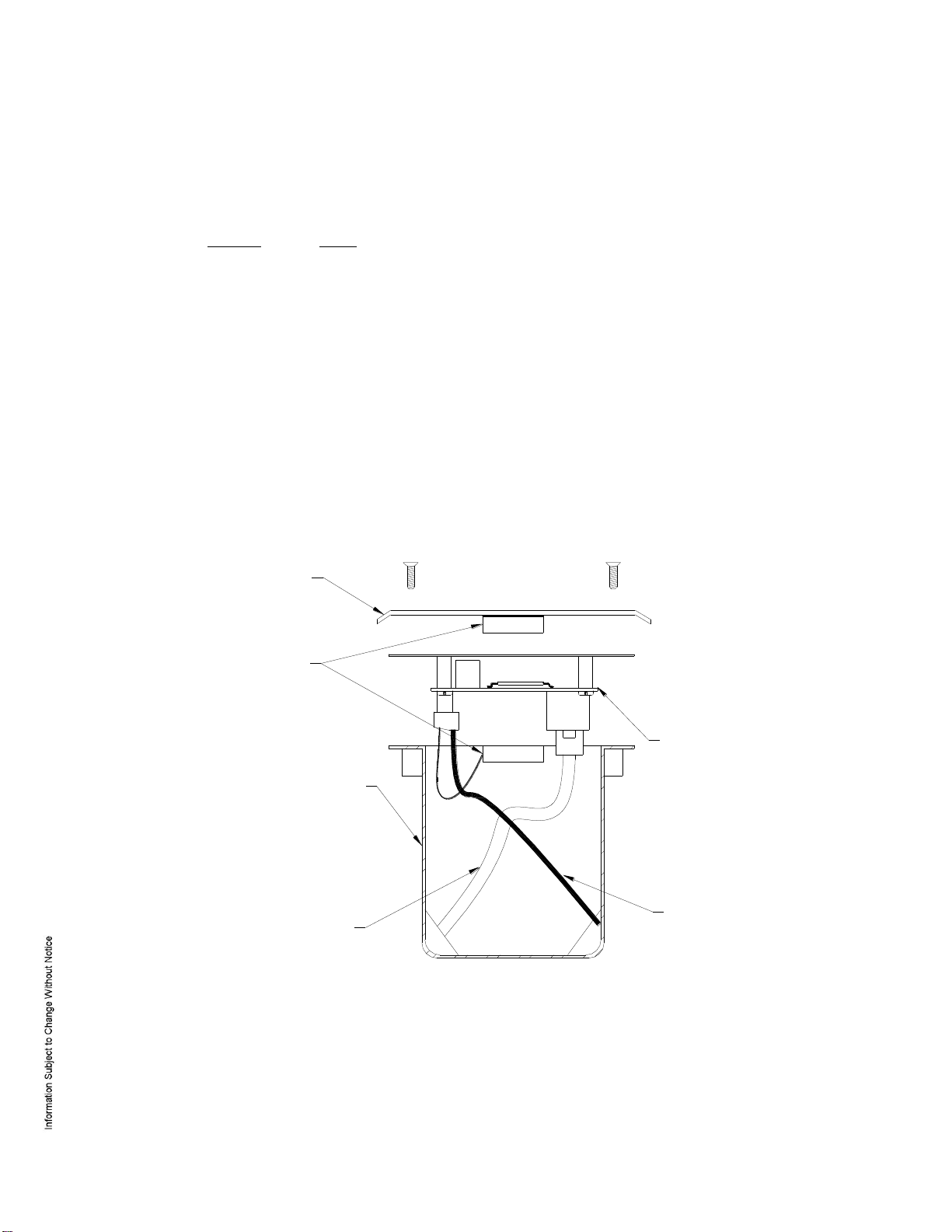
14. Additional Mounting Information:
Sources for the optional items shown below:
3-gang stainless steel blank cover. Available from:
Leviton part number 84033-40
Graybar part number 88158404
Magnetic switch set: G.R.I. part number: 505
Side View:
FIELD WIRING
MR51e WITH INCLUDED
MOUNTING PLATE
TO ETHERNET
NETWORK
OPTIONAL 3-GANG
JUNCTION BOX
OPTIONAL BLANK
COVER W/SCREWS
OPTIONAL MAGNETIC
TAMPER SWITCH

Mercury Security © 2019 MR62e DOC 10107-0057 REV 1.02 Page 8
Mounting Plate Dimensions:
Warranty
Mercury Security warrants the product is free from defects in material and workmanship under normal use
and service with proper maintenance for one year from the date of factory shipment. Mercury Security
assumes no responsibility for products damaged by improper handling or installation. This warranty is
limited to the repair or replacement of the defective unit.
There are no expressed warranties other than set forth herein. Mercury Security does not make, nor
intends, nor does it authorize any agent or representative to make any other warranties, or implied
warranties, and expressly excludes and disclaims all implied warranties of merchantability or fitness for a
particular purpose.
All returns must be accompanied by a Return Material Authorization (RMA) number obtained from customer
service, and prepaid postage and insurance.
Liability
The Interface should only be used to control exits from areas where an alternative method for exit is
available. This product is not intended for, nor is rated for operation in life-critical control applications.
Mercury Security is not liable under any circumstances for loss or damage caused by or partially caused
by the misapplication or malfunction of the product. Mercury Security’s liability does not extend beyond the
purchase price of the product.
3.85 [97.8]
2.35 [59.7]
5.50 [139.7]
3.63 [92.1]
3.30 [83.8]
3.63 [92.1]
Ø0.16 [Ø4.0]
MR50 MGT HOLES
4PL
Ø0.16 [Ø4.0]
3-GANG MGT HOLES
4PL
Other Mercury Security Recording Equipment manuals

Popular Recording Equipment manuals by other brands


Genelec
Genelec 9301B operating manual

Vernier
Vernier LabQuest Mini manual

Sensor Electronics
Sensor Electronics SEC 3500 HMI Hardware manual

Mitsubishi Electric
Mitsubishi Electric RMF-CA100-V1 Installation instructions manual

Oakley
Oakley 5U user manual

Hughes & Kettner
Hughes & Kettner FSM-432 MK IV manual