Merging Technologies Horus User manual

Horus User Manual
Horus User Manual
Revision 0.32 16.02.16

www.merging.com/horus Page 2
Horus User Manual
Horus Warranty Information ...................................................................................................................9
Contacting Merging .................................................................................................................................9
Introduction to Horus ............................................................................................................................11
Horus block diagram .............................................................................................................................11
Horus modules interconnection diagram............................................................................................13
Horus optional cards........................................................................................................................................................16
Horus cables...........................................................................................................................................30
Horus key features.................................................................................................................................35
Horus Modules Capabilities...........................................................................................................................................37
Horus Modules Latencies ...............................................................................................................................................37
Installing an additional Horus I/O Module ...........................................................................................38
Installing an additional Horus MADI Extension Module (MADM or MADS).............................................39
Installing the Merging PCIe Ethernet Controller Card NET-MSC-GBEX1.......................................42
Horus recommended placement in Rack ............................................................................................44
Horus power ON.....................................................................................................................................44
Horus touch screen control interface..................................................................................................45
Horus Menu Hierarchy....................................................................................................................................................45
Main Home Screen ............................................................................................................................................................46
Headphone Menu...............................................................................................................................................................46
Meters Menu........................................................................................................................................................................47
Meters Settings Menu ......................................................................................................................................................47
IO & Sync Menu ..................................................................................................................................................................48
Timecode Menu (I/O & Sync).......................................................................................................................................49
REFS Menu (I/O & Sync).................................................................................................................................................50
PreAmp Menu .....................................................................................................................................................................50
Setup Menu...........................................................................................................................................................................53
Formats Menu (Setup).....................................................................................................................................................54
Routing Menu (Setup) .....................................................................................................................................................55
Modules Menu (Setup) ....................................................................................................................................................57
Modules: MADI Sub-Menu .............................................................................................................................................58
Modules: AES Sub-Menu.................................................................................................................................................59
Modules: A/D Sub-Menu ................................................................................................................................................59
Modules: ADA Sub-Menu................................................................................................................................................60
Modules: D/A Sub-Menu ................................................................................................................................................61
Modules: PT Sub-Menu ...................................................................................................................................................62
Modules: Loopback (hidden menu, available only for debug use) ...............................................................63
Presets Menu (Setup).......................................................................................................................................................64
System (Setup): ..................................................................................................................................................................65
Network Menu (Setup)....................................................................................................................................................66
Info (Setup):.........................................................................................................................................................................67
Horus Web Control access ...................................................................................................................68
Installing and accessing the Horus Control interface remotely .....................................................................68
The Horus embedded User Manual............................................................................................................................72
Horus & Hapi setup examples ..............................................................................................................74
..................................................................................................................................................................80
.................................................................................................................................................................................80
...........................................................................................................................................................................80
Block Diagram.....................................................................................................................................................................82
Horus Firmware update procedure ......................................................................................................84

www.merging.com/horus Page 3
Horus User Manual
Horus troubleshooting ..........................................................................................................................88
Horus on screen Error Report......................................................................................................................................88
How to provide Merging Support with a Horus debug dump file .................................................................90
Cannot access Horus remotely in Maintenance mode for Firmware update ...........................................91
Firewall and Antivirus.....................................................................................................................................................91
Symptom: Horus does not start up or will after a few minutes .....................................................................92

www.merging.com/horus Page 4
Horus User Manual
IMPORTANT SAFETY AND
INSTALLATION INSTRUCTION
SAVE THESE INSTRUCTIONS
INSTRUCTIONS PERTAINING TO RISK OF FIRE, ELECTRIC
SHOCK, OR INJURY TO PERSONS
WARNING –when using electric products, basic precautions should be followed, including the following:
1. Read all of the safety and installations instructions and explanation of graphic symbols before using
the product.
2. The product must be grounded. If it should malfunction or breakdown, grounding provides a path of
least resistance or electric current to reduce the risk of electric shock. This product is equipped with a
power supply cord having an equipment-grounding conductor and a grounding plug. The plug must be
plugged into an appropriate outlet which is properly installed and grounded in accordance with all local
codes and ordinances.
DANGER –Improper connection of the equipment-grounding can result in a risk of electric shock. Do
not modify the plug provided with the product –if it will not fit the outlet have a proper outlet installed
by a qualified electrician. Do not use an adapter that defeats the function of the equipment-grounding
conductor. If you are in doubt as to whether the product is properly grounded, check with a qualified
serviceman or electrician.
3. Do not use this product near water –for example, near a bathtub, washbowl, kitchen sink, in a wet
basement, or near a swimming pool, or the like.
4. This product should only be used with a stand or cart that is recommended by the manufacture.
5. This product, either alone or in combination with an amplifier and speakers or headphones, may be
capable of producing sound levels that could cause permanent hearing loss. Do not operate at a high
volume level or at a level that is uncomfortable. If you experience any hearing loss or ringing in the
ears, you should consult an audiologist.
6. The product should be located so that its location or position does not interfere with its proper
ventilation.
7. The product should be located away from heat sources such as radiators, heat registers, or other
products that produce heat.
8. The product should be connected to a power supply only of the type described in the operating
instructions or as marked on the product.
9. The power-supply cord of the product should be unplugged from the outlet when left unused for a
long period of time. When unplugging the power supply, do not pull on the cord, but grasp it by the
plug.
10. Care should be taken so that objects do not fall and liquids are not spilled into the enclosure through
openings.
11. The product should be serviced by qualified service personnel when: A. The power supply cord or
plug has been damaged. Objects have fallen, or liquid has spilled into the product, or C. The product
has been exposed to rain, or D. The product does not appear to be operating normally or exhibits a
www.merging.com/horus Page 5
Horus User Manual
marked change in performance, or E. The product has been dropped, or the enclosure damaged.
12. Do not attempt to service the product beyond that described in the user maintenance instructions.
All other servicing should be referred to qualified service personnel.
13. WARNING - Do not place objects on the power supply cord, or place the product in a position
where anyone could trip over, walk on, or roll anything over cords of any type. Do not allow the
product to rest on or be installed over cords of any type. Improper installations of this type create the
possibility of a fire hazard and/or personal injury.
The lightning flash with arrowhead symbol, within an equilateral triangle, is
intended to alert the user to the presence of uninsulated "dangerous voltage"
within the product's enclosure that may be of sufficient magnitude to constitute a risk
of electric shock to persons.
The exclamation point within an equilateral triangle is intended to alert the user
to the presence of important operating and maintenance (servicing) instructions
in the literature accompanying the product.
No part of this documentation may reproduced in any form whatsoever or be stored in any data retrieval
system without prior written permission of the copyright owners.
This documentation is supplied on an as-is basis. Information contained within this documentation is
subject to change at any time without notice and must not be relied upon.
All company and product names are ™ or Registered Trademarks ® of their respective owners.
Windows 7 is a trademark of Microsoft Corporation.
Merging Technologies makes no warranties express or implied regarding the Horus embedded
software, its quality, performance, merchantability or fitness for a particular purpose. The software is
supplied “as is” you, the purchaser, are assuming the entire risk of the results of using this Merging
Technologies software.
In no circumstances will Merging Technologies, its owners, directors, officers, employees or agents be
liable to you for any consequential, incidental or indirect loss or damages including loss of time, loss of
business, loss of profits, loss of data or similar resulting from the use of or inability to use the Merging
Technologies hardware and or software or for any defect in the hardware software or documentation.
© Copyright Merging Technologies Inc. 2014. All rights reserved.
www.merging.com/horus Page 6
Horus User Manual
.

www.merging.com/horus Page 7
Horus User Manual
Environmental Limits
System Office Environment Parameter Limits
ESD 15kV per Merging Environmental Test Specification

www.merging.com/horus Page 8
Horus User Manual
Declaration of Conformity
According to
EMC Directive 2004/108/EC
Product Horus
Manufacturer Merging Technologies SA
Le Verney 4
CH-1070 Puidoux
Switzerland
Electrical Rating 90-260 VAC, 50/60 Hz, 0.2 A (at 230V)
Standards EN 55103-1:2009, EN 55103-2:2009, EN 61000-3-
2 :2006+A1+A2, EN 61000-3-3 :2008
Detailed specifications of the tested and certified product are shown in the
following Test Report:
Test report Ref No: 16'835 Issued Date: June 2012 by Montena EMC SA
The CE label is affixed on the rear of left side of the Horus unit as per below :
Date 12 June 2012
Claude Cellier
President
Merging Technologies S.A.

www.merging.com/horus Page 9
Horus User Manual
Horus Warranty Information
* Replacing or adding a AD, DA or MADI module and adjusting the DA module dip switch (output) is permitted
under the supervision of a Merging sales partner. Any other modification will void the Horus warranty.
Contacting Merging
www.merging.com

www.merging.com/horus Page 10
Horus User Manual

www.merging.com/horus Page 11
Horus User Manual
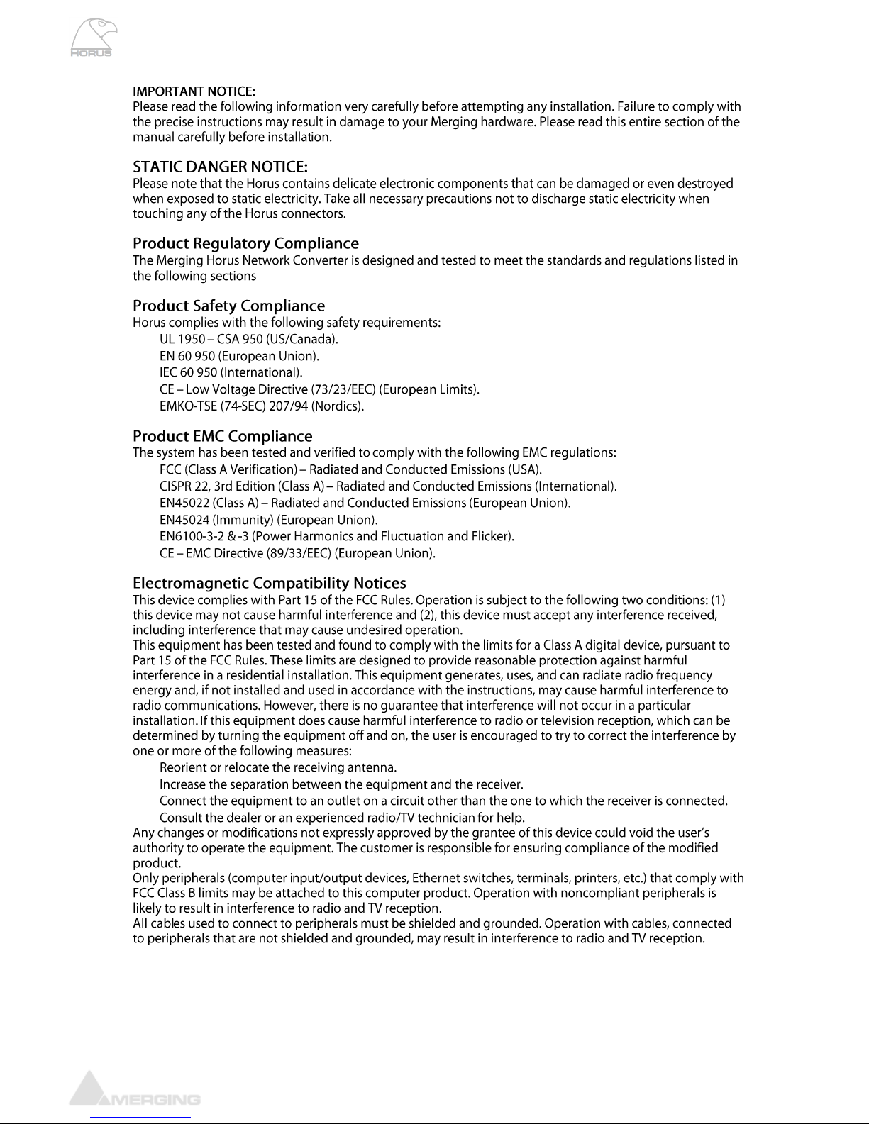
Introduction to Horus
Horus block diagram

www.merging.com/horus Page 12
Horus User Manual
www.merging.com/horus Page 13
Horus User Manual
Horus modules interconnection diagram
www.merging.com/horus Page 14
Horus User Manual
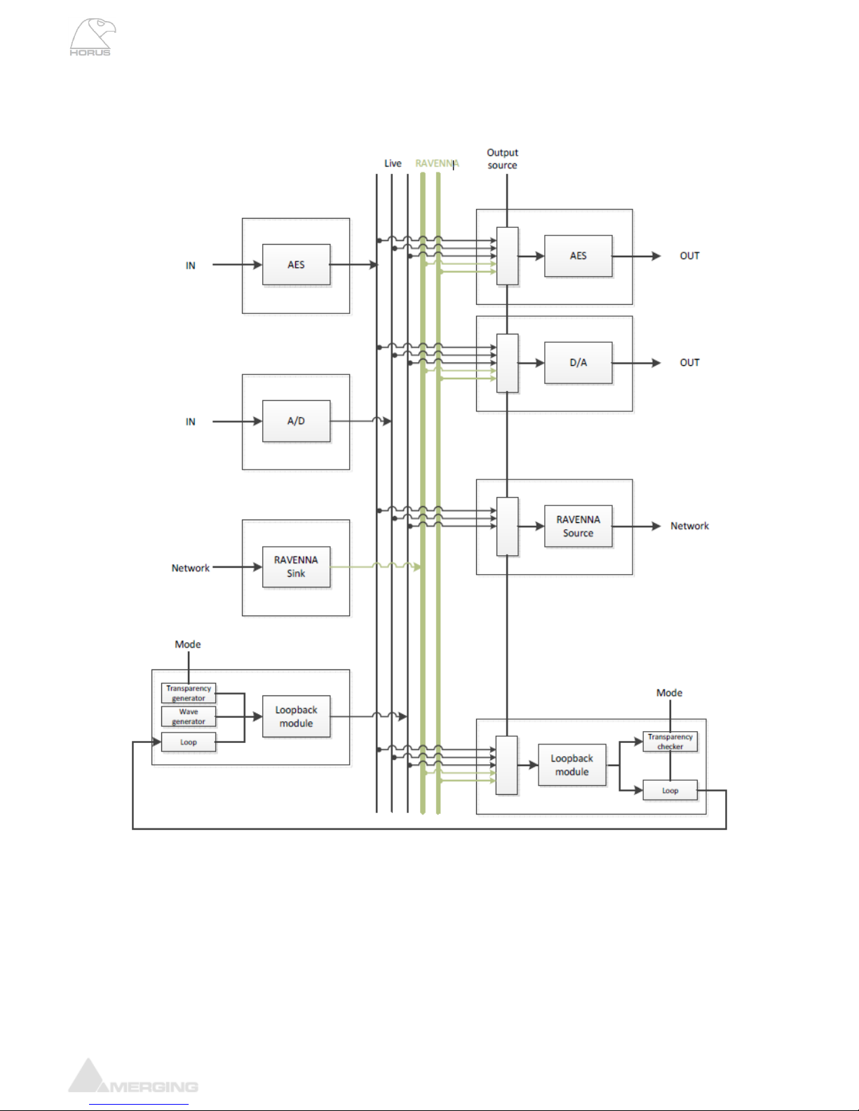
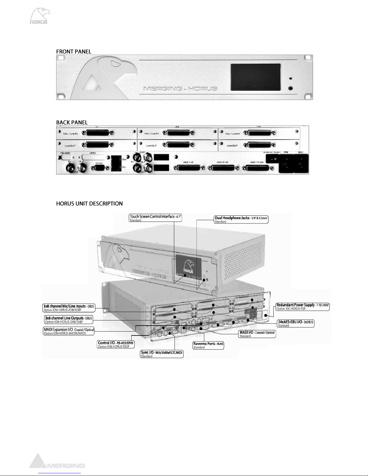
HORUS HARDWARE
www.merging.com/horus Page 15
Horus User Manual
HORUS BASE UNIT
75 Ω
(Switchable 75 Ω Termination)
= 35 Ω)
Ω
75 Ω

www.merging.com/horus Page 16
Horus User Manual
Horus optional cards
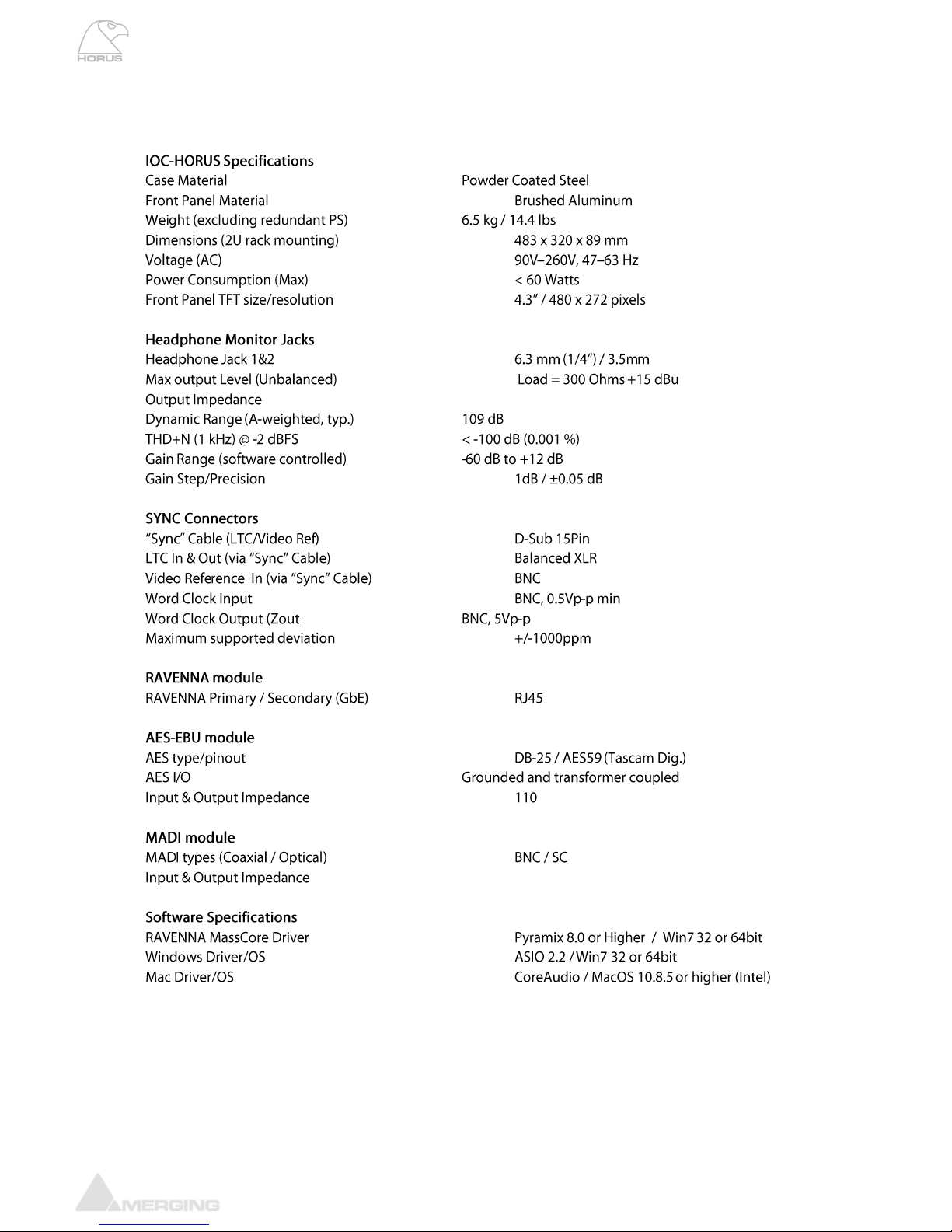
IOM-H-AD8D / AD8DP
These remotely controlled Mic/Line Input cards have set a new benchmark in analog circuitry design,
and provide additionally a Line level post Mic-pre “Direct Out” output.
Available in models that work up to 192kHz (AD8D) and DXD/DSD256 (AD8DP)
IOM-H-AD8D / AD8DP Key Features
• 8 x exceptionally transparent, Swiss designed pre-amplifiers
• Remote/Local switch to Line Level on a per channel basis
• Completely accessible remotely for all parameter changes
• Phantom Power/Phase/Low Cut switchable per channel
• Removes the need for DI boxes
• Allows build-in Mic splitting variants
• Better than 120dB dynamic range
IOM-H-AD8D / AD8DP Mic Pre-Amp + ADC
Mic Pre Max Input (Pad On / Pad Off) +24 dBu / +13 dBu
Input Impedance (Differential, Software Switchable Per Channel) 2 kΩ / 13.6 kΩ
Input Impedance with +48V ON (Diff., Soft. Switchable Per Channel) 1.7 kΩ / 6.8 kΩ
Dynamic Range (A-weighted, typ.) , ref +10 dBu 127 dB
Gain Range (software controlled) 0 dB to +66 dB
Gain Step/Precision 0.5 dB / ±0.2 dB
THD+N Pre + A/D (20 Hz-20 kHz) @ -2 dBFS (AD8/AD8P) < -96dB (0.0016 %) / -100 dB (0.001 %)
Interchannel Crosstalk @ 1kHz, typ. < -125 dB
EIN @ >40 dB Gain (150Ω Source Impedance, A-weighted, typ.) < -128 dBu
Common Mode Rejection Rate (20 Hz –20 kHz) > 60 dB (up to 0 dBFS)
Phantom Power (Software Switchable Per Channel) +48V
Phase Reverse (Software Switchable Per Channel) YES
Low Cut filter (Software Switchable Per Channel) -12 dB/octave, 80 Hz
Line Input
Max Line Input for 0 dBFS +24 dBu
Input Impedance (Differential) 13.6 kΩ
Dynamic Range (A-weighted, typ), ref +24 dBu 120 dB
THD+N Line+A/D (20 Hz - 20 kHz) @ -12 dBFS < -100 dB (0.001%)
Interchannel Crosstalk @ 1kHz @ fullscale < -120 dB
Sensitivity Range for 0 dBFS (software controlled) -42 dBu to +24 dBu
Gain Step/Precision 0.5 dB / ±0.2 dB
Common Mode Rejection Rate (20 Hz –20 kHz) > 60 dB (up to 0 dBFS)
Connector Pinout DB-25 / AES59 (Tascam Ana.)

www.merging.com/horus Page 17
Horus User Manual
IOM-H-AD8D/AD8DP Mic-Pre Analog Section
Frequency response +0/-0.5 dB, Line 5 Hz - 75 kHz
Frequency response +0/-2.0 dB, Line 2.5 Hz - 150 kHz
Frequency response +0/-0.5 dB, Mic 10 Hz - 100 kHz
Frequency response +0/-2.0 dB, Mic 5 Hz - 200 kHz
THD+N (1 kHz), Line/Mic at G=0dB <-115 dB (0.00018 %)
THD+N (20 Hz-20 kHz) , Line/Mic at G=0dB <-112 dB (0.00025 %)
Interchannel Crosstalk @ 1kHz, typ. -135dB
5° low-end in-channel Ø deviation pt: Line 13 Hz
5° low-end in-channel Ø deviation pt: Mic 35 Hz
Interchannel phase 10 Hz - 100 kHz < ±0.1°
IOM-H-AD8D/AD8DP Direct Out Section
Frequency response +0/-0.3dB @ Gain 40dB 10 Hz –50kHz
Max Direct Output level typ. +24 dBu
Output Impedance (Differential) < 100 Ω
Dynamic Range (A-weighted, typ) 133 dB
THD+N (1 kHz) @ +10dBu < -120dB (0.0001 %)
Input Connector Pinout DB-25 / AES59 (Tascam Ana.)
Direct Output Connector Pinout DB-25 / AES59 (Tascam Ana.)
Gain behavior of the Direct Out section
As the Direct Out output is taken just after the Mic-pre analog section, the gain adjustments are not as
smooth and linear as after the digital conversion. The figure below shows the behaviour of the gain on
the Direct Out (in blue) compared to the gain on the digital side (in red).
Note: on the Direct Out the maximum available gain is + 40.1 dB.

www.merging.com/horus Page 18
Horus User Manual
Mic / Line pad
-11dB
48V phantom
power
On / Off
Preamp
analog gain
0 to + 40dB
AD8D / AD8DP run 1 to run 8
A/D converter
Analog input
Digital gain
Direct Out
+18dBu
Analog output
Preamp
analog gain
0 to + 40dB
48V phantom
power
On / Off
Mic / Line pad
-11dB
AD8D / AD8DP run 9 and above
A/D converter
Analog input
Digital gain
Direct Out
+13/+24dBu
Analog output
Zin selector
2kΩ/ 6.8kΩ/ 13kΩ
2kΩ: dynamic mic (no phantom)
6.8kΩ: condenser mic (with phantom ON)
13.6kΩ: line input
www.merging.com/horus Page 19
Horus User Manual
IOM-HORUS-DA8/DA8P
The DA8 (up to 192kHz) and the DA8P (up to DSD) have been shown in testing to be consistently the
quietest multichannel D/A conversion modules available anywhere.
IOM-HORUS-DA8/DA8P Key Features
• Auto-mute circuitry for “no-pop” power cycling
• Digitally controlled trims for line up procedures
• Dynamic range of 127dB (typ.)
• Easy to set dip switches for international operating levels
IOM-HORUS-DA8/DA8P Specifications
Max Line Output @ 0 dBFS (jumpers on +24 dBu) +24 dBu +0/-0.5 dB
Frequency response +0/-0.3dB @ fs = 48000 Hz 6 Hz –20 kHz
Frequency response +0/-0.3dB @ fs = 2.8224 MHz (DSD) NA / 6 Hz –20 kHz
Frequency response +0/-3.0dB @ fs = 2.8224 MHz (DSD) NA / 2 Hz –50 kHz
Line Output Impedance (Differential) 100 Ω
Dynamic Range (A-weighted, typ) 126 dB
THD+N D/A (1 kHz) @ 0 dBFS (IOM-HORUS-DA8) < -113dB (0.00022 %)
THD+N D/A (1 kHz) @ 0 dBFS (IOM-HORUS-DA8P) < -115dB (0.00018 %)
Interchannel Crosstalk @ 1kHz, typ. -135 dB
Connector Pinout DB-25 / AES59 (Tascam Ana.)

www.merging.com/horus Page 20
Horus User Manual
Line Output Level calibration
The DA8 and DA8P modules feature both hardware level settings and a software fine adjustment to
align the Analog Output levels to whatever local/organization operational levels are mandated.
On DA8/DA8P cards from run 7 upwards, the hardware level setting is done via software through the
option “max output level” in each DA’s setting page, allowing either + 24 dBu or 18 dBu max level.
On DA8/DA8P cards prior to run 7 the hardware level setting is in the form of 4 DIP switches per output
channel
The Hardware settings will usually be set only once, at product installation, and only if the desired
Operating Line Level differs from the default ex-factory settings of +18 dBu for 0 dBFS.
Procedure for Hardware alignment (for DA8 prior to run 7):
Output Level (dBu)
+24
+18
+15
+12
Switch
S1 to S8
1
ON
ON
2
ON
ON
3
ON
ON
4
ON
ON
Other manuals for Horus
1
Table of contents
Other Merging Technologies Accessories manuals


Popular Accessories manuals by other brands


Mantracourt
Mantracourt BroadWeigh Original instructions

Hornbach
Hornbach 6145082 Installation and user manual

MaxiCosi
MaxiCosi Shape of You Instructions for use

C.P. Electronics
C.P. Electronics SPIR-F installation guide

Festo
Festo SFAH Instructions & Operating

C.P. Electronics
C.P. Electronics MWS1A-PRM Product guide


