Merging Technologies Sphynx User manual

Sphynx
Modular High Resolution Audio Interface
User Manual
Version: DOC-1.7 (April 2000)
© 2000 Merging Technologies Inc.


Sphynx User Manual © 2000 Merging Technologies i
Table of Contents
TABLE OF CONTENTS....................................................................................................................................... I
IMPORTANT NOTICE:.................................................................................................................................... III
STATIC DANGER NOTICE: ........................................................................................................................... III
INFORMATION FOR THE USER: ................................................................................................................. III
CONTACTING MERGING .............................................................................................................................. III
SPHYNX WARRANTY INFORMATION....................................................................................................... IV
CHAPTER 1 – INTRODUCTION .......................................................................................................................1
CHAPTER 2 – THE FRONT PANEL .................................................................................................................2
SYNCHRONIZATION SELECTION AND STATUS .......................................................................................................2
SAMPLE RATE SELECTION AND STATUS ...............................................................................................................3
AutoDetect SR mode ....................................................................................................................................3
INPUT LEVEL METERING.......................................................................................................................................4
MONITORING SELECTION......................................................................................................................................4
ADDITIONAL FRONT PANEL CONTROLS ................................................................................................................4
WARNINGS DISPLAYED.........................................................................................................................................5
Synchronization LEDs blinking....................................................................................................................5
Sample Rate LEDs blinking .........................................................................................................................5
Input Level Meters LEDs blinking ...............................................................................................................5
Monitor OUT LEDs blinking .......................................................................................................................5
CHAPTER 3 – THE BACK PANEL....................................................................................................................6
AUDIO INPUTS ......................................................................................................................................................6
Analog Inputs ...............................................................................................................................................6
AES-EBU Inputs ..........................................................................................................................................6
AUDIO OUTPUTS ...................................................................................................................................................7
Analog Outputs.............................................................................................................................................7
AES-EBU Outputs........................................................................................................................................7
AES-EBU REF. INPUT..........................................................................................................................................7
VIDEO/WORDCLOCK I/O.......................................................................................................................................8
Input..............................................................................................................................................................8
Loop..............................................................................................................................................................8
Output ...........................................................................................................................................................8
S/PDIF I/O ...........................................................................................................................................................8
Input..............................................................................................................................................................8
Output ...........................................................................................................................................................8
ODI (OPTICAL DIGITAL INTERFACE) I/O..............................................................................................................8
ODI-A Input .................................................................................................................................................8
ODI-B Input..................................................................................................................................................9
ODI-A Output...............................................................................................................................................9
ODI-B Output ...............................................................................................................................................9
AUXILIARY MODULES ..........................................................................................................................................9
POWER CONNECTOR .............................................................................................................................................9
CHAPTER 4 - ADDING/REMOVING I/O MODULES..................................................................................10
REMOVING THE TOP COVER ...............................................................................................................................10
PLACEMENT OF I/O MODULES ............................................................................................................................10

ii © 2000 Merging Technologies Sphynx User Manual
CHAPTER 5 - MAKING AUDIO CONNECTIONS........................................................................................11
CONNECTING ANALOG INPUTS ...........................................................................................................................11
CONNECTING ANALOG OUTPUTS........................................................................................................................11
CONNECTING AES-EBU INPUTS ........................................................................................................................12
CONNECTING AES-EBU OUTPUTS.....................................................................................................................12
TYPICAL CONNECTION SCENARIOS.....................................................................................................................13
SOFTIMAGE®|DS with SONY® Digital BetaCam Users........................................................................13
SOFTIMAGE®|DS with SONY® Analog BetaCam Users .......................................................................14
MERGING® Pyramix 3.0 DAW Setup......................................................................................................15
STAND ALONE Analog/Digital Audio Setup...........................................................................................16
CHAPTER 6 - POWER-UP ................................................................................................................................17
POWER-UP SEQUENCE.........................................................................................................................................17
DISPLAY OF SPHYNX CONFIGURATION ...............................................................................................................17
I/O MODULES PLACEMENT MISMATCH ..............................................................................................................17
ANALOG MODULES CALIBRATION......................................................................................................................17
CHAPTER 7 - SETTINGS MENU.....................................................................................................................18
1 - ANALOG I/O LEVEL.......................................................................................................................................19
Using the Trim Pots ....................................................................................................................................19
2 - ANALOG INPUT DITHER.................................................................................................................................19
3 - AES-EBU INPUT SRC ..................................................................................................................................19
Using the Sample Rate Conversion ............................................................................................................19
4 - AES-EBU I/O DUAL MODE ........................................................................................................................20
5 - ODI-B OUT ROUTING SELECTION................................................................................................................21
6 - STAND ALONE MODE ...............................................................................................................................21
7 - WCLK I/O IN ‘X2’ SR MODE .......................................................................................................................21
APPENDIX 1 – TECHNICAL SPECIFICATIONS .........................................................................................22
SPHYNX UNIT ......................................................................................................................................................22
48KHZ ANALOG INPUT MODULE ........................................................................................................................22
48KHZ ANALOG OUTPUT MODULE.....................................................................................................................22
96KHZ ANALOG INPUT MODULE ........................................................................................................................23
96KHZ ANALOG OUTPUT MODULE.....................................................................................................................23
AES-EBU INPUT MODULE .................................................................................................................................24
AES-EBU OUTPUT MODULE .............................................................................................................................24
APPENDIX 2 – FLOW CHART DIAGRAMS .................................................................................................24
SPHYNX SYNCHRONIZATION FLOW CHART ........................................................................................................24
SPHYNX IN ‘X1’ SR MODE AUDIO FLOW CHART ................................................................................................25
SPHYNX IN ‘X2’ SR MODE AUDIO FLOW CHART ................................................................................................25
APPENDIX 3 - UPGRADING THE SPHYNX FIRMWARE .........................................................................26
APPENDIX 4 – TROUBLESHOOTING / FAQ ...............................................................................................27
APPENDIX 5 – GLOSSARY OF TERMS ........................................................................................................29

Sphynx User Manual © 2000 Merging Technologies iii
IMPORTANT NOTICE:
Please read the following information very carefully before attempting any installation. Failure to comply with
the precise instructions may result in damage to your Merging hardware. Please read this entire section of the
manual carefully before installation.
STATIC DANGER NOTICE:
Please note that the Sphynx Audio Interface and I/O module cards contain delicate electronic components that
can be damaged or even destroyed when exposed to static electricity. Please take all of the necessary
precautions when handling the Sphynx with the cover removed and all other electronic cards such as the I/O
modules. This notice also applies when performing a firmware upgrade. Take all necessary precautions not to
discharge static electricity when touching any of the Sphynx internals.
INFORMATION FOR THE USER:
This device complies with part 15 of FCC rules. Operation is subject to the following two conditions: (1) This device
may not cause harmful interference, and (2) This device must accept any interference received, including interference
that may cause undesired operation.
This equipment has been tested and found to comply with the limits for a Class A digital device, pursuant to Part 15
of the FCC rules. These limits are designed to provide reasonable protection against harmful interference in a
residential installation. This equipment generates, uses and can radiate radio frequency energy and, if not installed
and used in accordance with the instructions contained in this manual, may cause harmful interference to radio and
television communications. However, there is no guarantee that interference will not occur in a particular installation.
If this equipment does cause harmful interference to radio and television reception, which can be determined by
turning the equipment off and on, the user is encouraged to try to correct the interference by one or more of the
following measures:
Reorient or relocate the receiving antenna
Increase the separation between the equipment and the receiver
Connect the equipment into an outlet on a circuit different from that of the receiver
Consult the dealer or an experienced audio television technician
NOTE: Connecting this device to peripheral devices that do not comply with CLASS A requirements or using an
unshielded peripheral data cable could also result in harmful interference to radio or television reception. The user is
cautioned that any changes or modifications not expressly approved by the party responsible for compliance could
void the user’s authority to operate this equipment. To ensure that the use of this product does not contribute to
interference, it is necessary to use shielded I/O cables.
EMC: The Sphynx complies with the following specifications:
CENELEC EN 55103-1
CENELEC EN 55103-2 (E4 Environment)
Contacting Merging
For all general or sales inquiries:
In Europe, contact our Sales Office: Tel: +41 21 946 04 44 or Fax +41 21 946 04 45
In the U.S., contact our Illinois Office: Tel: +1-847-272-0500 or Fax: +1-847- 272-0597
All documentation inquiries, bug reports or suggestions for improvement can be directed to: [email protected]m

iv © 2000 Merging Technologies Sphynx User Manual
Sphynx Warranty Information
This product is warranted to be free of defects in materials and workmanship for a period of one year from the date of
purchase. This Limited Warranty is extended by Merging Technologies, Inc. to the original purchaser.
In the event of a defect or failure to confirm to this Limited warranty, Merging Technologies, Inc. will repair or
replace the product without charge within sixty (60) days. In order to make a claim under this limited warranty; the
purchaser must notify Merging Technologies, Inc. or their representative in writing, of the product failure. In this
limited warranty the customer must upon Merging Technologies, Inc. request, return the product to the place of
purchase, or other local designation, for the necessary repairs to be performed. If the consumer is not satisfied with
the repair, Merging Technologies, Inc. will have the option to either attempt a further repair, or refund the purchase
price.
This warranty does not cover: (1) Products which have been subject to misuse, abuse, accident, physical damage,
neglect, exposure to fire, water or excessive changes in the climate or temperature, or operation outside maximum
rating. (2) Products on which warranty stickers or product serial numbers have been removed, altered or rendered
illegible. (3) The cost of installations, removal or reinstallation. (4) Damages caused to any other products.

Sphynx User Manual © 2000 Merging Technologies 1
Chapter 1 – Introduction
Congratulations on your Sphynx purchase. The Sphynx is a professional high quality, modular audio interface
solution for MERGING® Pyramix users, SOFTIMAGE®|DS users and audio professionals.
Features include:
Modular I/O design. The modularity of this unit allows for custom configurations based on quality and audio
interface requirements.
This extended modularity also offers an easy and low-cost upgrade path as user requirements evolve, new standards
emerge and converter technology progresses.
Up to 8 inputs and 8 outputs, in a single unit, using industry standard audio connections.
The signals from the input modules are also fed to the optical lightpipes in ADAT compatible format. This allows a
direct connection to ADAT compatible multitrack devices and other devices such as digital consoles. These optical
lightpipe connectors support up to 8 channels of 24 bit audio on one single optical fiber with no risk at all of line hum
or any other electromagnetic interference.
Rugged internal power supply. This unit accepts both 110 and 220 voltages for worldwide use.
Fully tested for CE compliance for guaranteed safety and stability.
All I/O modules audio connections are made using high quality balanced XLR type connectors.
Clear and easy to use front panel controls.
Extremely high quality 24 bit A/D and D/A using the latest generation in converter technology.
High common mode rejection balanced input circuitry on all analog input modules for optimum rejection of power
line hum, RF interference, voltage drops and other externally generated noise commonly encountered with long audio
cable runs.
All analog balanced output circuitry incorporates the advanced "Twin Servo Drive" output stage for maximum output
signal balance ratio performance, even under adverse asymmetrical loads.
DVD Ready. Support for high Sample Rates such as 96 kHz at 24-bit resolution.
Fits into standard 2 unit 19” rack.
Local control from the front panel (in stand-alone mode).
Remote control from Pyramix Virtual Studio Software.
Selectable monitoring of all 8 inputs and outputs
Very comprehensive choice of Sync sources
Very low jitter and calibrated internal clock

2 © 2000 Merging Technologies Sphynx User Manual
Chapter 2 – The Front Panel
PHONES
VOLUME
INT ODI AES WCLK
REMOTE
POWER
sphynx MODULAR HIGH RESOLUTION AUDIO INTERFACE
VIDEO S/PDIF
LOCK
x4x2x1
32 44.1 48
LVL
OVL
LVL
OVL
LVL
OVL
LVL
OVL
LVL
OVL
LVL
OVL
LVL
OVL
LVL
OVL 5/6
5/6
3/4
3/4
7/8
7/8
1/2
1/2
IN
OUT
SAMPLE RATE (KH )
SYNCHRONIZATION INPUT LEVEL METERS MONITOR
SELECT SELECTSELECT CH.1 CH.2 CH.3 CH.4 CH.5 CH.6 CH.7 CH.8
Synchroni ation
Selection & Status
Sample Rate
Selection & Status
Input Level
Metering
Monitoring
Selection
Synchronization Selection and Status
INT ODI AES WCLKVIDEO S/PDIF
LOCK
SYNCHRONIZATION
SELECT
The Sphynx can operate in many different synchronization modes. It can synchronize to its internal clock or to a wide
range of industry standard external sources. Pressing the SELECT button allows the selection of the desired
Synchronization mode.
INT:
Sphynx synchronizes and locks to its internal calibrated clock.
ODI:
Sphynx synchronizes to the optical input (ADAT). If no valid sync signal is present at the optical input (when the ODI
mode is selected), the ODI LED will flash. Once a valid sync signal has been detected at the optical input, the ODI
LED will remain lit. If the sample rate of the Sphynx and the ADAT signal are identical, the LOCK LED will light.
The Sphynx is now locked and synchronized to the incoming ADAT signal.
AES:
Sphynx synchronizes to an AES-EBU signal. If no valid sync signal is present at the AES-EBU input (when the AES
mode is selected), the AES LED will flash. Once a valid AES-EBU sync signal has been detected, the AES LED will
remain lit. If the sample rate of the Sphynx and the AES-EBU signal are identical, the LOCK LED will light. The
Sphynx is now locked and synchronized to the incoming AES-EBU signal. If a valid AES-EBU reference signal is
connected to the AES-EBU REF. input it will lock to the “Reference” input. If the Sphynx is equipped with many
AES-EBU input modules, and there is no valid AES-EBU signal connected to the "Reference" input, it will sync to
the first module, based on a priority scheme starting from the first module (input 1-2) to the fourth module (input 7-
8).

Sphynx User Manual © 2000 Merging Technologies 3
VIDEO:
Sphynx synchronizes to a video signal and automatically detects and adapts to either a PAL or NTSC signal. If no
valid sync signal is present at the video input (when the VIDEO sync mode is selected), the VIDEO LED will flash.
Once a valid video signal has been detected at the video input, the VIDEO LED will remain lit. If the video signal is
either a NTSC or PAL compliant signal, the LOCK LED will light. The Sphynx is now locked and synchronized to
the incoming video signal.
WCLK:
Sphynx synchronizes to a Wordclock signal (TTL or CMOS level square wave at the sampling rate selected on the
front panel). If no valid sync signal is present at the Wordclock input (when the WCLK mode is selected), the WCLK
LED will flash. Once a valid sync signal has been detected at the Wordclock input, the WCLK LED will remain lit. If
the sample rate of the Sphynx and the Wordclock signal are identical, the LOCK LED will light. The Sphynx is now
locked and synchronized to the incoming Wordclock signal.
S/PDIF:
Sphynx synchronizes to a S/PDIF signal. If no valid sync signal is present at the S/PDIF input (when the S/PDIF mode
is selected), the S/PDIF LED will flash. Once a valid sync signal has been detected at the S/PDIF input, the S/PDIF
LED will remain lit. If the sample rate of the Sphynx and the S/PDIF signal are identical, the LOCK LED will light.
The Sphynx is now locked and synchronized to the incoming S/PDIF signal.
Sample Rate Selection and Status
x4x2x1
32 44.1 48
SAMPLE RATE (KH )
SELECT
Sphynx supports a wide range of sample rates. The desired rate is selected by pressing the SELECT button.
There are three possible modes available when selecting sample rates.
Mode x1: In this mode, the available sample rates are: 32 kHz, 44.1 kHz, 48 kHz and AutoDetect.
Mode x2: In this mode, the available sample rates are: 64 kHz, 88.2 kHz, 96 kHz and AutoDetect.
Mode x4: In this mode, the available sample rates are: 128 kHz, 176.4 kHz, 192 kHz and AutoDetect.
Switching between modes is allowed by pressing the SELECT button for more than ~2s.
AutoDetect SR mode
In this mode, the sample rate is automatically determined and selected based on the signal present at the selected
synchronization source.
When in AutoDetect SR mode, the X1, X2 or X4 LED flashes.
For selected sync sources such as INT, ODI or VIDEO, the analysis of the incoming (and desired) sampling rate is
based on the signal present at the ODI input (usually the return from the Workstation or system to which Sphynx
would be connected to both ways). This allows for completely automatic sample rate detection and switching for
Sphynx when using Merging’s Pyramix Workstation, SOFTIMAGE®|DS, or other external ADAT compatible
devices such as Multitrack Digital Recorders or Digital Mixing Consoles.
For selected sync sources such as AES, WCLK or S/PDIF, the analysis of the incoming (and desired) sampling rate is
based on the actual sampling rate present at the selected sync source (AES-EBU, WCLK or S/PDIF).

4 © 2000 Merging Technologies Sphynx User Manual
Input Level Metering
LVL
OVL
LVL
OVL
LVL
OVL
LVL
OVL
LVL
OVL
LVL
OVL
LVL
OVL
LVL
OVL
INPUT LEVEL METERS
CH.1 CH.2 CH.3 CH.4 CH.5 CH.6 CH.7 CH.8
These meters provide a very quick and independent state of the current input signals detected on the input modules.
They relay the following information:
LVL - This LED will light if an input signal is detected above –60 dB FS. This is also useful to verify the presence of
any audio at the input.
OVL - This LED will light if an input signal is detected above –0.5 dB FS. This is useful to indicate that the input
audio signal is close to clipping or indeed clipping has occurred. When this occurs, either a reduction of the analog
source level or a decrease in the sensitivity of the analog input of the Sphynx is required (see Chapter 7 for details on
how to calibrate the analog I/O level).
Note: dB FS are referred to Digital Full Scale.
Monitoring Selection
PHONES
VOLUME
5/6
5/6
3/4
3/4
7/8
7/8
1/2
1/2
IN
OUT
MONITOR
SELECT
This section allows for the selection and headphone level control of any of the 8 input or output audio signals in pairs.
The desired monitor source is selected by pressing the SELECT button.
Headphones (stereo ¼ inch plug) are plugged into the PHONES jack and the VOLUME control adjusts the volume level.
Additional Front Panel Controls
REMOTE
POWER
Power Switch
This switch toggles the power source on and off. See Chapter 6 for details on power-up sequence.
Remote indicator
The REMOTE LED type indicator indicates whether the Sphynx unit is in remote or local control. If the REMOTE LED
is lit, the Sphynx is in remote control. In this mode, the Sphynx front panel controls are being controlled via a
software application (such as the Merging Pyramix Workstation).

Sphynx User Manual © 2000 Merging Technologies 5
Warnings Displayed
See the troubleshooting section in Appendix 4 for details on most common sources of warnings.
Synchronization LEDs blinking
If the selected synchronization LED blinks, it indicates that the signal present at the selected synchronization input is
not valid (maybe at a different sample rate than the Sphynx).
While no valid sync signal is detected, the Sphynx is kept in calibrated Internal sync mode.
Sample Rate LEDs blinking
The X1 or X2 LED is blinking. This is a warning to remember you that the Sphynx is set in AutoDetect SR mode
In this mode, the Sphynx may change the sampling rate automatically, based on the selected synchronization source
and its status, without any intervention of the user.
Input Level Meters LEDs blinking
The Input Level Meters OVL LEDs blink (whith the corresponding LVL LEDs turned off) on some channels when the
input module of those channels has a problem.
Here is the cause of this warning for each type of input module:
Analog Input 96KHz:
The module is muted while initialized. A 30s warm up delay is necessary for those modules.
AES-EBU Input:
A simple blink means that a sample has just been dropped or re-read, because the incoming AES-EBU signal is not
synchronized to the Sphynx clock (drift).
A constant blinking means that the incoming AES-EBU signal is not valid (maybe at a wrong sample rate).
Monitor OUT LEDs blinking
If all monitor OUT LEDs flash, this is an indication that the ODI-A input can’t be decoded properly. In that event, the
Sphynx software mutes all its outputs.
In ‘x2’ sample rate mode, if monitor LEDs OUT5/6 and OUT7/8 only flash, this is an indication that the ODI-B input
can’t be decoded properly. In that event, the Sphynx software mutes its output channels 5/6 and 7/8.

6 © 2000 Merging Technologies Sphynx User Manual
Chapter 3 – The Back Panel
SERIAL #
MERGING TECHNOLOGIES, Le Verney, CH 1604, Puidoux, Swit erland
AC 100-250 VAC
50 / 60 H
OUTPUTS
INPUTS
123
45678
123
45678
AES-EBU1/2 AES-EBU3/4 AES-EBU 5/6 AES-EBU 7/8
LINE LINE LINE LINE LINE LINE LINE
LINE LINE LINE LINE LINE LINE LINE
VIDEO/WORDCLOCK S/PDIF ODI
INPUT LOOP OUTPUT INPUT INPUT INPUTOUTPUT OUTPUT OUTPUT
AB
MADE IN UK
AUX1 AUX2
Audio Inputs
Audio Outputs Auxiliary
Modules
Power
Connector
AES-EBU
Reference Input
Video &
WordClock I/O S/PDIF I/O Optical Digital
Interface I/O
AES-EBU 1/2 AES-EBU 3/4 AES-EBU 5/6 AES-EBU 7/8 AES-EBU REF
Audio Inputs
The Sphynx unit supports up to eight inputs. The inputs format is determined by the type of input modules installed in
the Sphynx. Currently the Sphynx supports the following input modules:
24 bit analog line inputs (up to 48 kHz)
24 bit analog line inputs (up to 96 kHz)
24 bit AES-EBU inputs (up to 96 kHz)
Sphynx can accommodate up to 4 input modules, each having two discreet inputs.
INPUTS
123
45678
LINE LINE LINE LINE LINE LINE LINE
AES-EBU 1/2 AES-EBU 3/4 AES-EBU 5/6 AES-EBU 7/8
As mentioned above, the input connectors are mapped in pairs to the corresponding input modules.
See Chapter 5 on how to make audio connections.
Analog Inputs
When using analog input modules, the corresponding input XLR connectors are adjustable, balanced + 4 dBu
nominal line level (headroom 20dB) analog inputs.
AES-EBU Inputs
When using AES-EBU input modules, the corresponding input XLR connectors (only those XLRs corresponding to
odd line inputs should be used) are balanced, AES-EBU inputs.

Sphynx User Manual © 2000 Merging Technologies 7
Audio Outputs
The Sphynx unit supports up to eight outputs. The outputs format is determined by the type of output modules
installed in the Sphynx. Currently the Sphynx supports the following output modules:
24 bit analog line outputs (up to 48 kHz)
24 bit analog line outputs (up to 96 kHz)
24 bit AES-EBU output (up to 96 kHz)
Sphynx can accommodate up to 4 output modules, each having two discreet outputs.
OUTPUTS
123
45678
AES-EBU1/2 AES-EBU3/4 AES-EBU 5/6 AES-EBU 7/8
LINE LINE LINE LINE LINE LINE LINE
As mentioned above, the output connectors are mapped in pairs to the corresponding output modules.
See Chapter 5 on how to make audio connections.
Analog Outputs
When using analog output modules, the corresponding output XLR connectors are adjustable, balanced + 4 dBu
nominal line level (headroom 20dB) analog outputs.
AES-EBU Outputs
When using AES-EBU output modules, the corresponding output XLR connectors (only those XLRs corresponding
to odd line outputs should be used) are balanced AES-EBU outputs.
AES-EBU Ref. Input
AES-EBU REF
This XLR input accepts any balanced AES-EBU signal up to 48 KHz.
This reference is used primarily when the Sphynx is placed into AES sync mode.
When the Sphynx is set in ‘x2’ SR mode, this input will only accept an AES-EBU signal of FS/2 sample rate.
For example, when set to 96 KHz, the Sphynx would lock on a 48 KHz AES-EBU signal present at this input.

8 © 2000 Merging Technologies Sphynx User Manual
Video/Wordclock I/O
VIDEO/WORDCLOCK
INPUT LOOP OUTPUT
Input
This BNC type connector has two functions. It can accept any NTSC (29.97 fps) or PAL (25 fps) video signal or any
Wordclock signals. See Chapter 7 on how to configure the Wordclock input.
When Sphynx is set to VIDEO sync mode, it will resolve the Sphynx clock to the video signal present here.
When Sphynx is set to WCLK sync mode, it will sync the Sphynx clock to the Wordclock signal present here.
Loop
This BNC connector reflects the video or Wordclock signal present at the VIDEO/WORDCLOCK input.
Care should be taken to ensure proper termination if the Loop connector is not used. Placing a 75-Ohm terminator on
the loop output should provide adequate termination in most cases. See your Video Reference Generator User’s
Guide for more information on proper termination techniques.
Output
This BNC connector outputs a Wordclock signal based on the current Sphynx sampling rate. This signal is always
present. See Chapter 7 on how to configure the Wordclock output.
S/PDIF I/O
S/PDIF
INPUT OUTPUT
Input
The coaxial S/PDIF input is only used when the Sphynx is placed in S/PDIF sync mode.
In this sync mode, the Sphynx routes the two S/PDIF input channels on the input channels 1-2, in place of input
module 1/2. When using the S/PDIF input, the module present in slot IN1/2 is ignored.
Note that the S/PDIF input is available only when using the Sphynx in ‘x1’ SR mode.
Output
The output signals present on output channels 1-2 are sent in parallel to module in slot OUT1/2 and to the coaxial
S/PDIF output.
Note that the S/PDIF output is available only when using the Sphynx in ‘x1’ SR mode.
ODI (Optical Digital Interface) I/O
ODI
INPUT INPUTOUTPUT OUTPUT
AB
ODI-A Input
This EIAJ optical connector receives a signal from any ADAT compatible output.
The signal present at this input is conveyed to outputs 1-8 in ‘x1’ SR mode, and to outputs 1-4 in ‘x2’ SR mode.

Sphynx User Manual © 2000 Merging Technologies 9
ODI-B Input
This EIAJ optical connector receives a signal from any ADAT compatible output.
The signal present at this input is conveyed to outputs 5-8 in ‘x2’ SR mode.
In ‘x1’ SR mode and S/PDIF sync, this input accepts an S/PDIF compatible format signal (the Sphynx detects and
selects automatically between the coaxial and the ODI-B inputs).
ODI-A Output
This EIAJ optical connector transmits a signal to any ADAT compatible input.
This output conveys signals present at inputs 1-8 in ‘x1’ SR mode, and inputs 1-4 in ‘x2’ SR mode.
ODI-B Output
This EIAJ optical connector transmits a signal to any ADAT or S/PDIF compatible input.
In ‘x2’ SR mode, this output conveys signals present at inputs 5-8 in ADAT format.
In ‘x1’ SR mode, the signal routed to this output is selectable via the Settings Menu.
See Chapter 7 on how to set the ODI-B OUT routing.
Auxiliary Modules
AUX1 AUX2
The AUX-1 and AUX-2 modules are reserved for future I/O modules that will be developed by Merging
Technologies.
Power Connector
AC 100-250 VAC
50 / 60 H
Sphynx uses a variable power supply that accepts AC from 100 to 250 volts. It is designed to be connected to an
outlet that includes three pins (center pin to ground). The ground connection is an important safety feature designed
to keep potentially dangerous voltages away from the chassis. Never defeat the ground safety feature.
Never operate the Sphynx with ungrounded outlets. Plugging the Sphynx into an ungrounded outlet, or
defeating the ground pin, can create a potentially hazardous condition. Merging Technologies cannot be held
responsible for problems caused to Sphynx or any associated equipment with improper AC connections.

10 © 2000 Merging Technologies Sphynx User Manual
Chapter 4 - Adding/Removing I/O Modules
Removing the Top Cover
In order to add or remove I/O modules, the ten top cover screws need to be removed.
As a safety precaution, the unit must be switched off and the power cable unplugged before opening the top cover.
Placement of I/O Modules
The Sphynx I/O modules are plugged into the white PCI-type connectors located in the Sphynx.
Align the I/O module to fit properly in the desired slot.
Insert the module firmly into place.
Please note that the output modules are physically longer than the input modules. This reduces the chance of the
output modules being incorrectly inserted into an input slot. The input modules can however be inserted into the
output slots (this will not cause any damage to the I/O module or Sphynx).
Caution: Never try to insert any Sphynx I/O modules into a PC computer PCI slot. This could damage both the
computer and the Sphynx module.
I/O Module Slots
The four input and output slots are displayed here.
SPHYNX
4 In
p
ut Slots
4 Out
p
ut Slots
SPHYNX

Sphynx User Manual © 2000 Merging Technologies 11
Chapter 5 - Making Audio Connections
Connecting Analog Inputs
Any professional level balanced audio output source can be connected to the analog inputs of the Sphynx. The input
format used is determined by the type of input modules installed in Sphynx. The XLR inputs on the rear of the
Sphynx map to installed analog input modules as shown below.
INP UTS
123
45678
LINE LINE LINE LINE LINE LINE LINE
AES-EBU 1/2 AES-EBU 3/4 AES-EBU 5/6 AES-EBU 7/8
Analog Input
Module #1
Analog Input
Module #2
Analog Input
Module #3
Analog Input
Module #4
Note that the rear panel labeling of the analog XLR inputs is “MIC/LINE”. Currently, the Sphynx only accepts line
analog inputs.
Connecting Analog Outputs
Any professional level balanced audio input sources can be connected to the analog outputs of the Sphynx. The
output format used is determined by the type of output modules installed in Sphynx. The XLR outputs on the rear of
the Sphynx map to installed analog output modules as shown below.
OUTPUTS
123
45678
AES-EBU 1/2 AES-EBU 3/4 AES-EBU 5/6 AES-EBU 7/8
LINE LINE LINE LINE LINE LINE LINE
Analog Output
Module #1
Analog Output
Module #2
Analog Output
Module #3
Analog Output
Module #4
12 © 2000 Merging Technologies Sphynx User Manual
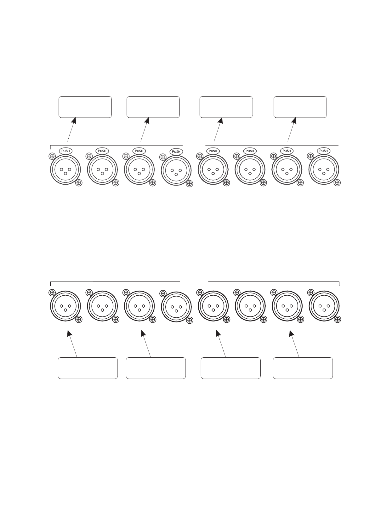
Connecting AES-EBU Inputs
Any professional level balanced digital AES-EBU audio outputs sources can be connected to the AES-EBU inputs of
the Sphynx. The input format used is determined by the type of input modules installed in Sphynx. The XLR inputs
on the rear of the Sphynx map to installed AES-EBU input modules as shown below.
INP UTS
123
45678
LINE LINE LINE LINE LINE LINE LINE
AES-EBU 1/2 AES-EBU 3/4 AES-EBU 5/6 AES-EBU 7/8
AES-EBU Input
Module #1
AES-EBU Input
Module #2
AES-EBU Input
Module #3
AES-EBU Input
Module #4
Connecting AES-EBU Outputs
Any professional level balanced digital AES-EBU audio input sources can be connected to the AES-EBU outputs of
the Sphynx. The output format used is determined by the type of output modules installed in Sphynx. The XLR
outputs on the rear of the Sphynx map to installed AES-EBU output modules as shown below.
OUTPUTS
1 2 3 45 6 7 8
AES-EBU 1/2 AES-EBU 3/4 AES-EBU 5/6 AES-EBU 7/8
LINE LINE LINE LINE LINE LINE LINE
AES-EBU Output
Module #1
AES-EBU Output
Module #2
AES-EBU Output
Module #3
AES-EBU Output
Module #4

Sphynx User Manual © 2000 Merging Technologies 13
Typical Connection Scenarios
This section will display some typical audio connection scenarios for Sphynx.
SOFTIMAGE®|DS with SONY®Digital BetaCam Users
This example is based on Digital Studio users who are using the Sphynx in conjunction with the Merging Keops
boards and a Digital Betacam video deck.
MYKERINOS
Card
VIDEO / TC
Bracket
SOFTIMAGE|DS
Computer
SONY
Digital Betacam
Video Deck
AES-EBU
INPUTS
AES-EBU
OUPUTS
Audio
Monitoring
Sphynx Modular
Audio Interface
AES-EBU
INPUTS
ODI-A
I/OADAT
AES-EBU
OUTPUTS
ANALOG
OUTPUTS
ANALOG
INPUTS
Monitor
Outputs
Video Ref.
Black Burst
Generator
Monitoring on
Headphones
Analog
Audio Source
ODI-B
I/OADAT
VIDEO
Sync
This example uses the following:
Monitoring is done through the Digital Betacam analog outputs, the Sphynx headphones output, or the Sphynx analog
outputs (if analog output modules are installed).
The Sphynx contains at least 2 AES-EBU input modules (4 mono inputs) and 2 AES-EBU output modules (4 mono
outputs). Analog output modules are optional in this configuration.
All units (Mykerinos card – via TC card, Video Deck and Sphynx) are connected to the video reference generator.
Note that any composite video source can also be used as a video reference for Sphynx.
Note that the video Loop output can be used to supply the video reference to other devices.
Otherwise, a 75-Ohms terminator must be connected to the Loop output.
The Sphynx is set to VIDEO or AES-EBU Sync Mode.

14 © 2000 Merging Technologies Sphynx User Manual
SOFTIMAGE®|DS with SONY®Analog BetaCam Users
This example is based on Digital Studio users who are using the Sphynx in conjunction with the Merging Keops
boards and an Analog Betacam video deck.
MYKERINOS
Card
VIDEO / TC
Bracket
SOFTIMAGE|DS
Computer Sphynx Modular
Audio Interface
AES-EBU
INPUTS
ODI-A
I/OADAT
AES-EBU
OUTPUTS
ANALOG
OUTPUTS
ANALOG
INPUTS
Monitor
Outputs
Video Ref.
Black Burst
Generator
Monitoring on
Headphones
ODI-B
I/OADAT
VIDEO
Sync
ANALOG
INPUTS
ANALOG
OUTPUTS
SONY
Analog Betacam
Video Deck
This example uses the following:
All monitoring is done by the front panel Monitoring selection and output
The Sphynx contains 2 analog input modules (4 inputs) and 2 analog output modules (4 outputs)
AES-EBU output modules are optional in this configuration.
All units (Mykerinos card – via TC bracket, Video Deck and Sphynx) are connected to the Video Sync generator
Note that any composite video source can also be used as a Video Sync reference for Sphynx.
Note that the Video Loop output can be used to supply the video reference to other devices
Otherwise, a 75-Ohms terminator must be connected to the Loop output.
The Sphynx is set to VIDEO Sync Mode
Table of contents
Other Merging Technologies Accessories manuals


