Kobold KET User manual

Operating Instructions
for
Compact Inline Thermal Sensor
Model: KET

KET
page 2 KET K01/0323
We don’t accept warranty and liability claims neither upon this publication nor in
case of improper treatment of the described products.
The document may contain technical inaccuracies and typographical errors. The
content will be revised on a regular basis. These changes will be implemented in
later versions. The described products can be improved and changed at any time
without prior notice.
© Copyright
All rights reserved.
1. Contents
1.Contents ........................................................................................................ 2
2.Note .............................................................................................................. 4
3.Instrument Inspection .................................................................................... 4
4.Regulation Use ............................................................................................. 5
5.Safety instructions ......................................................................................... 6
6.Operating Principle ........................................................................................ 7
7.Scaling Analogue output Compressed Air ................................................. 8
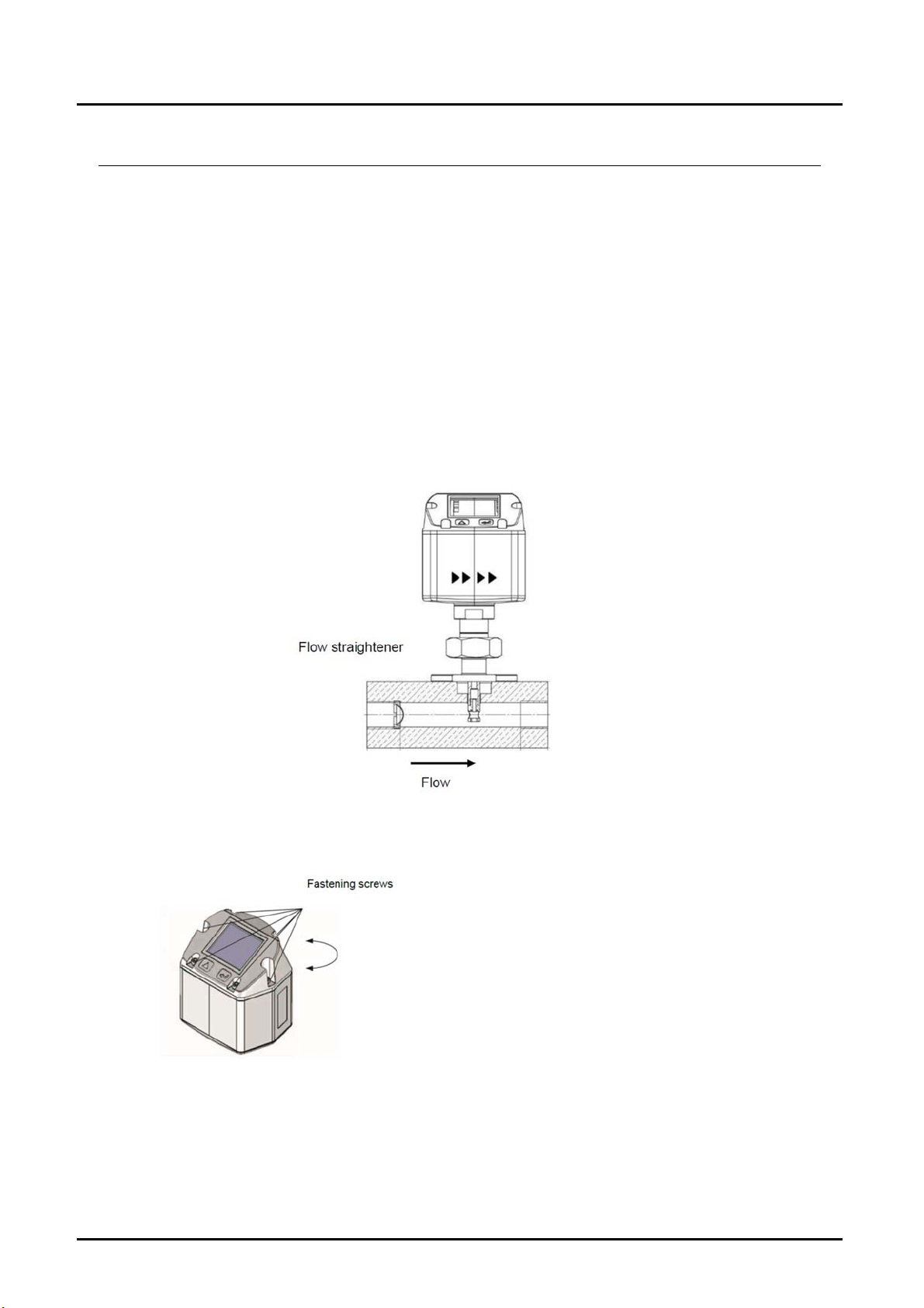
8.Installation Description ................................................................................... 9
8.1Installation of KET ............................................................................... 9
8.2Display head position ........................................................................... 9
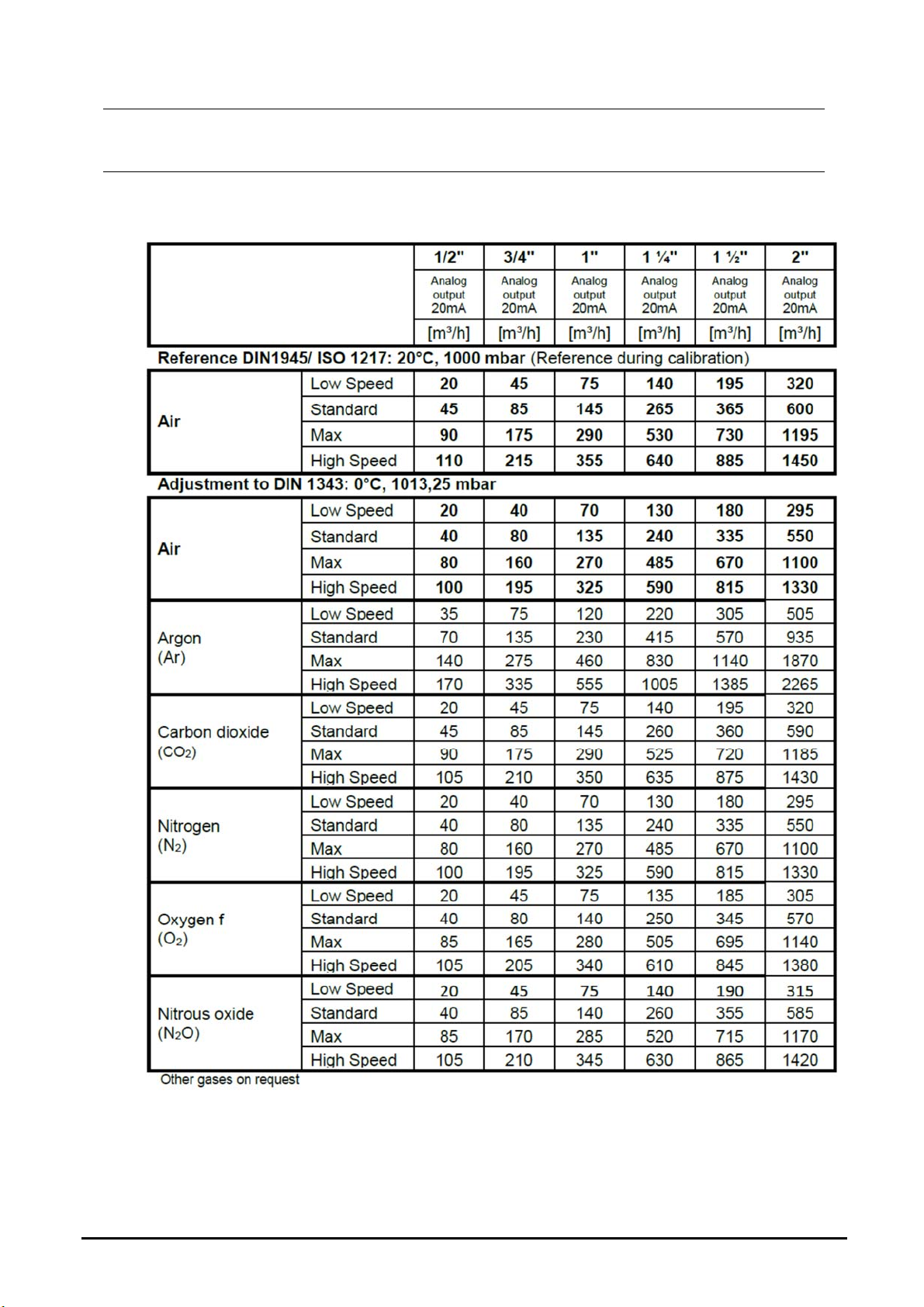
9.Flow measuring ranges ............................................................................... 10
9.1Flow for different gases ...................................................................... 10
10.Electrical wiring ........................................................................................... 11
10.1Modbus, 4…20 mA ............................................................................ 11
11.Operation .................................................................................................... 12
11.1Initialization ........................................................................................ 13
11.2Main menu ......................................................................................... 13
11.3Settings .............................................................................................. 14
12.Status / Error messages .............................................................................. 29
12.1Status messages ............................................................................... 29
12.2Error messages ................................................................................. 29
13.Maintenance ............................................................................................... 30
14.Cleaning of the sensor head ........................................................................ 31
15.Re-Calibration ............................................................................................. 31
16.Spare parts and repair ................................................................................. 31
17.Calibration ................................................................................................... 31
18.Technical Information .................................................................................. 32
19.Order Codes ............................................................................................... 32
20.Dimensions ................................................................................................. 32
21.Disposal ...................................................................................................... 33
22.EU Declaration of Conformance ................................................................. 34
23.UK Declaration of Conformity ...................................................................... 35

KET
KET K01/0323 page 3
Manufactured and sold by:
Kobold Messring GmbH
Nordring 22-24
D-65719 Hofheim
Tel.: +49(0)6192-2990
Fax: +49(0)6192-23398
E-Mail: [email protected]
Internet: www.kobold.com

KET
page 4 KET K01/0323
2. Note
Please read these operating instructions before unpacking and putting the unit into
operation. Follow the instructions precisely as described herein.
The instruction manuals on our website www.kobold.com are always for currently
manufactured version of our products. Due to technical changes, the instruction
manuals available online may not always correspond to the product version you
have purchased. If you need an instruction manual that corresponds to the
purchased product version, you can request it from us free of charge by email
([email protected]) in PDF format, specifying the relevant invoice number and
serial number. If you wish, the operating instructions can also be sent to you by
post in paper form against an applicable postage fee.
Operating instructions, data sheet, approvals and further information via the QR
code on the device or via www.kobold.com
The devices are only to be used, maintained and serviced by persons familiar with
these operating instructions and in accordance with local regulations applying to
Health & Safety and prevention of accidents.
When used in machines, the measuring unit should be used only when the
machines fulfil the EC machinery directive.
3. Instrument Inspection
Instruments are inspected before shipping and sent out in perfect condition.
Should damage to a device be visible, we recommend a thorough inspection of the
delivery packaging. In case of damage, please inform your parcel service /
forwarding agent immediately, since they are responsible for damages during
transit.
Scope of delivery:
The standard delivery includes:
Compact Inline Thermal Sensor Model: KET

KET
KET K01/0323 page 5
4. Regulation Use
Any use of the device, which exceeds the manufacturer’s specification, may
invalidate its warranty. Therefore, any resulting damage is not the responsibility of
the manufacturer. The user assumes all risk for such usage.
The KET consumption sensor is used for continuous flow measurements.
The KET consumption sensor is designed and constructed exclusively for the intended
purpose described here and may only be used accordingly.
The user must check whether the instrument is suitable for the selected application. It must
be ensured that the medium is compatible with the wetted parts. The technical data listed
in the data sheet are binding.
Improper handling or operation outside the technical specifications is not permitted. Claims
of any kind based on improper use are excluded.
Operating principle:
The KET consumption probe operates according to the calorimetric measuring method.
The basis of this measuring method is the electrical heating of the mechanically protected
built-in sensor. The mass flow, the volume flow and the flow velocity can be measured and
determined by the resulting heat flow to the passing medium (gas).
With the calorimetric measurement method (based on the measurement principle), the
operating temperature and pressure of the medium have no influence on the measurement
result, only the material data of the gas component are decisive.

KET
page 6 KET K01/0323
5. Safety instructions
Please read carefully before starting the device!
Warning: Do not exceed the pressure range of 16 bar! Observe the measuring
range of the sensor!
Always observe the direction of flow when positioning the sensor! The screwed
fixture must be pressure tight.
It is absolutely necessary to avoid condensation on the sensor element or water
drops in the measuring air as they may cause faulty measuring results.
The manufacturer cannot be held liable for any damage which occurs as a result of
non- observance or non-compliance with these instructions. Should the device be
tampered with in any manner other than a procedure which is described and
specified in the manual, the warranty is cancelled and the manufacturer is exempt
from liability.
The device is destined exclusively for the described application.
We offer no guarantee for the suitability for any other purpose and are not liable for
errors which may have slipped into this operation manual. We are also not liable
for consequential damage resulting from the delivery, capability or use of this
device.
We offer you to take back the instruments of the instruments family KET which you
would like to dispose of.
Qualified employees from the measurement and control technology branch should
only carry out adjustments and calibrations.
The consumption sensor KET works according to the calorimetric measuring
procedure.
Flammable gases
If this consumption sensor is used for measurement of flammable gases (e. g.
natural gas and so on) we expressly would like to point out that the sensor has no
DVGW admission, however, it can be used for measurements in natural gas. A
DVGW admission is not mandatory.
The consumption sensor corresponds with the current state of technology and
basically it can be used
in any flammable and non-flammable gases.
If the sensor is used e.g. in the medium natural gas, the sensor will be adjusted for
natural gas. The calibration protocol (inspection certificate) will be included in the
scope of delivery.
The area outside the pipeline (ambient area of the sensor) must not be an explosive
area.
The installation has to be carried out by authorized professionals.

KET
KET K01/0323 page 7
6. Operating Principle
The newly developed KET combines modern digital interfaces for connection to
energy monitoring systems with a small, compact design. The KET is always used
when many machines (compressed air consumers) are to be integrated into an
energy monitoring network.
Readout values in the display can be rotated by 180°, e.g. for overhead installation.
Display shows 2 values at the same time:
Present flow in m³/h, l/min, ...
Total consumption (counter reading) in m³, l, kg
Temperature measurement

KET
page 8 KET K01/0323
7. Scaling Analogue output Compressed Air
Reference DIN1945/ ISO 1217: 20°C, 1000 mbar (Reference during calibration)
Description Version Analogue output
KET with integrated ½” measuring block
Low Speed
4… 20 mA =
0...20 m³/h
Standard 0...45 m³/h
Max 0...90 m³/h
High Speed 0...110 m³/h
KET with integrated ¾” measuring block
Low Speed
4… 20 mA =
0...45 m³/h
Standard 0...85 m³/h
Max 0...175 m³/h
High Speed 0...215 m³/h
KET with integrated 1" measuring block
Low Speed
4… 20 mA =
0...75 m³/h
Standard 0...145 m³/h
Max 0...290 m³/h
High Speed 0...355 m³/h
KET with integrated 1¼” measuring
block
Low Speed
4… 20 mA =
0...140 m³/h
Standard 0...265 m³/h
Max 0...530 m³/h
High Speed 0...640 m³/h
KET with integrated 1½” measuring
block
Low Speed
4… 20 mA =
0...195 m³/h
Standard 0...365 m³/h
Max 0...730 m³/h
High Speed 0...885 m³/h
KET with integrated 2" measuring block
Low Speed
4… 20 mA =
0...320 m³/h
Standard 0...600 m³/h
Max 0…1195m³/h
High Speed 0...1450 m³/h

KET
KET K01/0323 page 9
8. Installation Description
8.1 Installation of KET
The sensor KET is pre-supplied with the measuring block.
An installation at customer site is only allowed in the unpressurized state
of the
system.
Tightness of the connection must be checked and ensured
The connecting nut is tightened to a torque of 25 -30 Nm.
It has to be checked whether the KET is correctly installed in the measuring
section, the flow direction arrows must point from the integrated flow
straightener
away.
8.2 Display head position
The Position of the Display head is twistable by
180 e.g., in
case of reverse flow direction.
For this purpose, the 6 fastening screws are to
be released
and the display head rotated 180°.
Caution:
It must be ensured that the connection plugs are
still plugged
and the gasket is installed correctly.

KET
page 10 KET K01/0323
9. Flow measuring ranges
9.1 Flow for different gases
Please note:
The area outside the pipeline (ambient area of the sensor) must not be an explosive
area.

KET
KET K01/0323 page 11
10. Electrical wiring
10.1 Modbus, 4…20 mA
Attention:
Not required connections NC must not be connected to a
voltage and/or to protection
earth. Cut and insulate cables.
Pin 1 Pin 2 Pin 3 Pin 4 Pin 5
Connector plug A +VB RS 485 (A) -VB RS 485 (B) I+
4..20 mA
Connector plug B
Pulse output (standard) NC GND DIR Pulse
galv. isolated
Pulse
galv. isolated
Colours pulse cables
0553 0106 (5 m)
0553.0107 (10 m)
brown
white
blue
black
grey
Legend:
If no connection cable/ pulse
cable
is ordered the sensor will
be
supplied with a M12
connector
plug. The user can
connect the
supply and signal
cables as
indicated in the
connection diagram.
-VB Negative supply voltage 0 V
+VB Positive supply voltage 18...36 VDC smoothed
I + Current signal 4...20 mA – selected measured
signal
RS 485 (A)
RS 485 (B)
Modbus RTU A
Modbus RTU A
Pulse Pulse for consumption
NC Must not be connected to a voltage
and/or to protection earth. Please cut
and isolate cables.

KET
page 12 KET K01/0323
Connector plug A (M12 - A-coding) Connector plug B (M12 - A-coding)
Remark: If the sensor is placed at the end of the Modbus system a termination is
required. The sensors have an
internal switchable termination, therefore the 6
fastening screws from the lid are to be released and set
the internal DIP Switch to
“On”. It must be ensured that the connection plugs are still plugged and the
gasket
is installed correctly, see also chapter 8.2.
Alternatively, a 120R resistor can be installed in the plug between pin 2 and pin 4.
11. Operation
Remark: Only for version with display
The operation of the KET is done by the two capacitive key buttons Up () and
Enter (
).

KET
KET K01/0323 page 13
11.1 Initialization
11.2 Main menu
Switching to pages 2-4 or back by pressing key “”
AV-Time (Period for average value calculation) could be changed under Sensor
Setup.-Advanced– AV-Time
After switching on the KET, the initialized
screen is displayed followed by the main
menu.

KET
page 14 KET K01/0323
11.3 Settings
The settings menu could accessed by pressing the key „OK“.
But the access to
the settings menu is password protected.
11.3.1 Sensor Setup
SetupSensorSetup
11.3.1.1 Input / change tube diameter
For KET not adjustable (suspended) as voted on included measuring section with
corresponding pipe
diameter.
Factory settings for password at the time of
delivery: 0000 (4 times zero).
If required the password could be changed at
Setup–Usersetup-Password.
.
53.1 mm
For changes, first select the menu item
with key „“ and then confirm it with
“OK“.
Selection of a menu item or to change a
value
is done with the key „“, a final
move to the
chosen menu item or
takeover of the value
change needs the
confirmation by pressing the
key „OK“

KET
KET K01/0323 page 15
11.3.1.2 Input / change consumption counter
SetupSensorSetupTotalCounterUnitbutton
Important!
When the counter reach 100000000 m³ the counter will be reset to zero.
11.3.1.3 Definition of the units for flow, velocity, temperature and pressure
SetupSensorSetupUnits
In order to change, e.g. the unit, first select by
pressing key „“ the button “Unit” and then
key “OK”.
Select with the key „“ the correct unit and
then confirm selection by pressing 2x „OK“.
Entering / changing the consumption counter
via button „“ , select the respective position
and activate the position with the "OK"
button.
By pressing „“ the position value is
incremented by 1. Complete with "OK" and
activate next number position.
Confirm entry by pressing „OK“.
To make changes to the unit for the respective
measurement value, first select by pressing
„“ the field of the „measurement value“ and
activate „it with „OK“ .
Selection of the new unit with „“
In case the quantity of units selectable are not
presentable on one page, pleas move to next
page by pressing „<<“ .
Confirm selection by pressing 2x „OK“.
Procedure for all 4 measurement variables is
analogous.

KET
page 16 KET K01/0323
11.3.1.4 Definition of the reference conditions
Here can be defined the desired measured media reference conditions for
pressure and temperature
and times for the filter and averaging.
Factory pre-setting for reference temperature and reference pressure are 20
°C, 1000 hPa
All volume flow values (m³/h) and consumption values
indicated in the display are
related to 20 °C and 1000
hPa (according to ISO 1217 intake condition)
Alternatively, 0 °C and 1013 hPa (=standard cubic meter) can also be
entered as a reference.
Do not enter the operation pressure or the operation temperature under
reference conditions!
SetupSensorSetupAdvanced
SetupSensorSetupAdvancedRef.Pref
Setup Sensor SetupAdvanced
Ref.Temp
To make changes, first select a menu with
button „“ and confirm selection by pressing
„OK“ .
In order to change, e.g. the unit, first select by
pressing key „“ the field “Units” and then
key “OK”.
Select with the key „“ the correct unit and
then confirm selection by pressing 2x „OK“.
Input / change of the value by selecting the
respective position with button „“and
entering by pressing button „OK“ .
By pressing „“ the position value is
incremented by 1. Complete with "OK" and
activate next number position.
Procedure for changing the reference
temperature is the same.

KET
KET K01/0323 page 17
Setup Sensor SetupAdvanced Filtertime
SetupSensorSetupAdvancedAV‐Time
11.3.1.5 Setting of Zero point and Low-flow cut off
SetupSensorSetupZPAdjust
Under item "Filtertime" " an attenuation can
be defined.
Input values of 0 -10000 in [ms] are possible
The time period for averaging can be entered
here.
Input values of -1440 1 [minutes] are possible.
For average values see display window 3 + 4
1,03
To make changes, first select a menu with
button „“ and confirm selection by pressing
„OK“ .

KET
page 18 KET K01/0323
SetupSensorSetupZPAdjustZeroPnt
SetupSensorSetupZPAdjustCutOff
SetupSensorSetupZPAdjusttReset
When, without flow, the installed sensor shows
already a flow value of > 0 m³/h herewith the
zero point of the characteristic could be reset.
For an input / change of the value select with
the button „“ the respective number position
and activate it with „OK“.
By pressing „“ the position value is
incremented by 1. Confirm the input with „OK“
and activate next number position.
Leave menu with button „Back“
With the low-flow cut off activated, the flow
below the defined "LowFlow Cut off" value will
be displayed as 0 m³/h and not added to the
consumption counter.
For an input / change of the value select with
the button „“ the respective number position
and activate it with „OK“.
By pressing „“ the position value is
incremented by 1. Confirm the input with „OK“
and activate next number position.
Leave menu with button „Back“
1,03
By selection of „Reset“ all settings for
„ZeroPnt“ and. „CutOff“ are reset.
Menu item to be select with button „“ and
confirm the reset with „OK“ .
Leave menu with button „Back“

KET
KET K01/0323 page 19
11.3.2 Modbus settings
11.3.2.1 Modbus RTU Setup
The Flow sensors KET comes with a Modbus RTU Interface. Before
commissioning the sensor, the communication parameters
Modbus ID, Baudrate, Parity und Stop bit
must be set in order to ensure the communication with the Modbus master.
SettingsModbusSetup
For changes, e.g. the sensor ID,
first select by pressing key „“ the field
“ID” and then key “OK”.
Select the desired position by pressing the
">" and select with "OK" button.
Change values by pressing the „“ values
takeover by pressing "OK".
Inputs for baud rate, stop bit and parity is
done analogue.
By means of the button "Byte Order" it is
possible to change the data format (Word
Order). Possible formats are "ABCD" (Little
Endian) and "CDAB" (Middle Endian)
Saving the changes by pressing "Save",
therefore select it with key „“ and then
confirm it with "OK".

KET
page 20 KET K01/0323
Default values out of factory: Modbus ID: 1
Baud rate: 19200
Stop bit: 1
Parity:
even
Byte Order: ABCD
Remark: If the sensor is placed at the end of the Modbus system a termination is
required. The sensors have an
internal switchable termination, therefore
the 6 fastening screws from the lid are to be released and set
the internal
DIP Switch to “On”.
Alternatively, a 120R resistor can be installed in the plug between pin 2 and pin 4.
It must be ensured that the connection plugs are still plugged and the gasket is
installed correctly, see
also chapter 4.5.
Dip Switch
Table of contents
Other Kobold Accessories manuals

Kobold
Kobold SEN-86 Series User manual

Kobold
Kobold SEN-33 Series User manual

Kobold
Kobold AFK-A User manual

Kobold
Kobold DRG-11 User manual

Kobold
Kobold DF-**01 series User manual

Kobold
Kobold HND-PS19 PS33 Series User manual

Kobold
Kobold MTE User manual

Kobold
Kobold NWP-1405 Series User manual

Kobold
Kobold OPT Series User manual

Kobold
Kobold Heinrichs TM User manual
Popular Accessories manuals by other brands

Palram Applications
Palram Applications Arizona 5000 Wave instructions

Focusrite
Focusrite Scarlett 18i8 user guide

Panasonic
Panasonic KX-HNS105C installation guide

Pfannenberg
Pfannenberg PWW 3482 Installation, operation and maintenance

Siko
Siko MSA511 User information

Vega
Vega VEGACAL 60 Series Safety manual