Merging DUA II User manual
DUA II
Audio Interface
User Manual
Version: DOC-1.0 (March 20, 2000)
© 2000 Merging Technologies

ii DUA II User Manual © 2000 Merging Technologies

© 2000 Merging Technologies DUA II User Manual iii
Table of Contents
IMPORTANT NOTICE:............................................................................................................................................IV
STATIC DANGER NOTICE: ...................................................................................................................................IV
INFORMATION FOR THE USER: .........................................................................................................................IV
CONTACTING MERGING ......................................................................................................................................IV
DUA II WARRANTY INFORMATION ................................................................................................................... V
CHAPTER 1 – INTRODUCTION .............................................................................................................................. 1
CHAPTER 2 – THE FRONT PANEL ........................................................................................................................ 2
SYNCHRONIZATION SELECTOR AND STATUS ............................................................................................................... 2
SAMPLE RATE SELECTOR............................................................................................................................................. 3
MONITORING SELECTOR .............................................................................................................................................. 3
MONITORING OUTPUTS................................................................................................................................................ 4
POWER SWITCH & REMOTE INDICATOR....................................................................................................................... 4
CHAPTER 3 – THE BACK PANEL........................................................................................................................... 5
ANALOG LINE INPUTS 1-4............................................................................................................................................ 5
ANALOG LINE OUTPUTS 1-4 ........................................................................................................................................ 5
AES/EBU INPUTS 5-8 ................................................................................................................................................. 6
AES/EBU OUTPUTS 5-8.............................................................................................................................................. 6
AES/EBU / WORD-CLOCK REFERENCE INPUT............................................................................................................ 6
ODI (OPTICAL DIGITAL INTERFACE)........................................................................................................................... 7
POWER CONNECTOR .................................................................................................................................................... 7
CHAPTER 4 – DIP SWITCH SETTINGS ................................................................................................................. 8
CHAPTER 5 – TYPICAL AUDIO CONNECTIONS ............................................................................................... 9
SOFTIMAGE®|DS WITH SONY DIGITAL BETACAM USERS ..................................................................................... 9
SOFTIMAGE®|DS WITH SONY ANALOG BETACAM USERS .................................................................................. 10
PYRAMIX WORKSTATION WITH SURROUND MONITORING USERS ............................................................................. 11
STAND ALONE A/D AND D/A SETUP ......................................................................................................................... 12
APPENDIX 1 – TECHNICAL SPECIFICATIONS ................................................................................................ 13
ANALOG LINE INPUTS................................................................................................................................................ 13
ANALOG LINE OUTPUTS ............................................................................................................................................ 13
AES/EBU INPUTS ..................................................................................................................................................... 13
AES/EBU OUTPUTS .................................................................................................................................................. 13
APPENDIX 2 – FLOW CHART DIAGRAMS ........................................................................................................ 14
DUA II AUDIO FLOW CHART .................................................................................................................................... 14
DUA II SYNCHRONIZATION FLOW CHART ................................................................................................................ 14
APPENDIX 3 - UPGRADING THE DUA II FIRMWARE .................................................................................... 15
APPENDIX 4 – TROUBLESHOOTING / FAQ ...................................................................................................... 15
APPENDIX 5 – GLOSSARY OF TERMS ............................................................................................................... 16

iv DUA II User Manual © 2000 Merging Technologies
IMPORTANT NOTICE:
Please read the following information very carefully before attempting any installation. Failure to comply with
the precise instructions may result in damage to your Merging hardware. Please read this entire section of the
manual carefully before installation.
STATIC DANGER NOTICE:
Please note that the DUA II Audio Interface contains delicate electronic components that can be damaged or
even destroyed when exposed to static electricity. Please take all of the necessary precautions when handling
the DUA II with the cover removed. This notice also applies when performing a Firmware Upgrade. Take all
necessary precautions not to discharge static electricity when touching any of the DUA II Internals.
INFORMATION FOR THE USER:
This device complies with part 15 of FCC rules. Operation is subject to the following two conditions: (1) This device
may not cause harmful interference, and (2) This device must accept any interference received, including interference
that may cause undesired operation.
This equipment has been tested and found to comply with the limits for a Class A digital device, pursuant to Part 15
of the FCC rules. These limits are designed to provide reasonable protection against harmful interference in a
residential installation. This equipment generates, uses and can radiate radio frequency energy and, if not installed
and used in accordance with the instructions contained in this manual, may cause harmful interference to radio and
television communications. However, there is no guarantee that interference will not occur in a particular installation.
If this equipment does cause harmful interference to radio and television reception, which can be determined by
turning the equipment off and on, the user is encouraged to try to correct the interference by one or more of the
following measures:
• Reorient or relocate the receiving antenna
• Increase the separation between the equipment and the receiver
• Connect the equipment into an outlet on a circuit different from that of the receiver
• Consult the dealer or an experienced audio television technician
NOTE: Connecting this device to peripheral devices that do not comply with CLASS A requirements or using an
unshielded peripheral data cable could also result in harmful interference to radio or television reception. The user is
cautioned that any changes or modifications not expressly approved by the party responsible for compliance could
void the user’s authority to operate this equipment. To ensure that the use of this product does not contribute to
interference, it is necessary to use shielded I/O cables.
EMC:
The DUA II complies with the following specifications:
CENELEC EN 55103-1
CENELEC EN 55103-2 (E4 Environment)
Contacting Merging
For all general or sales inquiries:
In Europe, contact our Swiss Office:
Tel: +41-21-946 0444 or Fax +41-21-946 0445
In the U.S., contact our Illinois Office:
Tel: +1-847-272-0500 or Fax: +1-847- 272-0597
All documentation inquiries, bug reports or suggestions for improvement can be directed to: info@merging.com

© 2000 Merging Technologies DUA II User Manual v
DUA II Warranty Information
This product is warranted to be free of defects in materials and workmanship for a period of one year from the date of
purchase. This Limited Warranty is extended by Merging Technologies, Inc. to the original purchaser.
In the event of a defect or failure to confirm to this Limited warranty, Merging Technologies, Inc. will repair or
replace the product without charge within sixty (60) days. In order to make a claim under this limited warranty; the
purchaser must notify Merging Technologies, Inc. or their representative in writing, of the product failure. In this
limited warranty the customer must upon Merging Technologies, Inc. request, return the product to the place of
purchase, or other local designation, for the necessary repairs to be performed. If the consumer is not satisfied with
the repair, Merging Technologies, Inc. will have the option to either attempt a further repair, or refund the purchase
price.
This warranty does not cover: (1) Products which have been subject to misuse, abuse, accident, physical damage,
neglect, exposure to fire, water or excessive changes in the climate or temperature, or operation outside maximum
rating. (2) Products on which warranty stickers or product serial numbers have been removed, altered or rendered
illegible. (3) The cost of installations, removal or reinstallation. (4) Damages caused to any other products.

vi DUA II User Manual © 2000 Merging Technologies

© 2000 Merging Technologies DUA II User Manual 1
Chapter 1 – Introduction
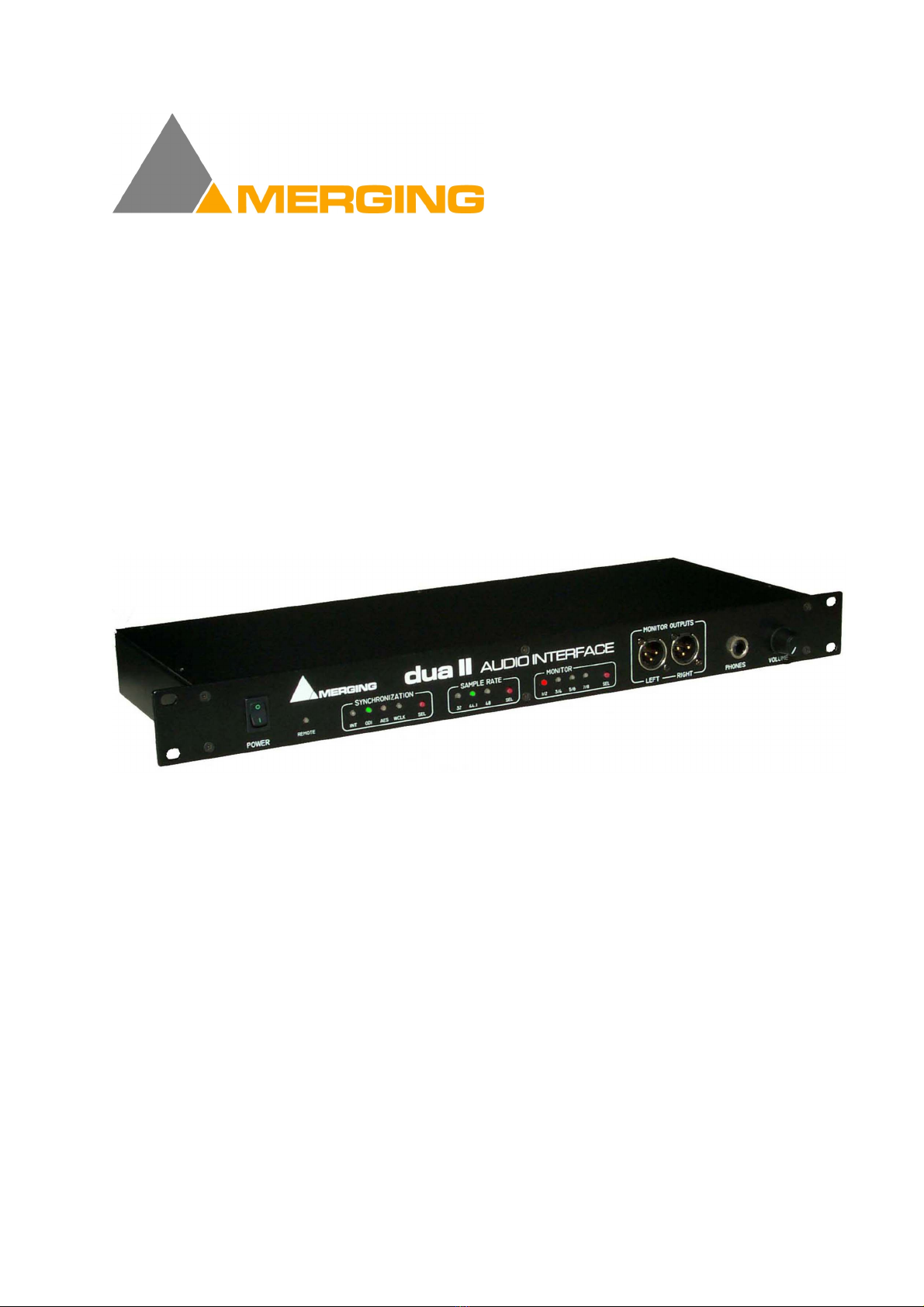
Congratulations on your DUA II purchase. The DUA II is the smartest audio interface solution for Pyramix users,
SOFTIMAGE®|DS users and audio professionals, designed to support a surround monitoring system.
Features include:
• In a single unit, using industry standard audio connections:
4 CH analog line inputs,
4 CH analog line outputs,
2 CH analog line outputs + headphones connector for monitoring,
4 CH AES/EBU inputs,
4 CH AES/EBU outputs.
• The signals from the inputs are also fed to the optical lightpipes in ADAT compatible format. This allows a direct
connection to ADAT compatible multitrack devices and other devices such as digital consoles. These optical
lightpipe connectors support up to 8 channels of 24 bit digital audio on one single optical fiber with no risk at all
of line hum or any other electromagnetic interference.
• Rugged internal power supply. This unit accepts both 110 and 220 voltages for worldwide use.
• All audio connections are made using high quality balanced XLR type connectors.
• Clear and easy to use front panel controls.
• High quality 24 bit A/D and D/A using the latest generation in converter technology.
• High common mode rejection balanced input circuitry on all analog input for optimum rejection of power line
hum, RF interference, voltage drops and other externally generated noise commonly encountered with long audio
cable runs.
• All analog balanced output circuitry incorporates the advanced "Twin Servo Drive" output stage for maximum
output signal balance ratio performance, even under adverse asymmetrical loads.
• Fits into standard 1 unit 19” rack.
• Local control from the front panel (in stand-alone mode).
• Remote control from Pyramix Virtual Studio software.
• Selectable stereo monitoring of all 8 inputs and outputs.
• Very comprehensive choice of synchronization sources.
• Very low jitter and calibrated internal clock.
• Fully tested for CE compliance for guaranteed safety and stability.
2 DUA II User Manual © 2000 Merging Technologies
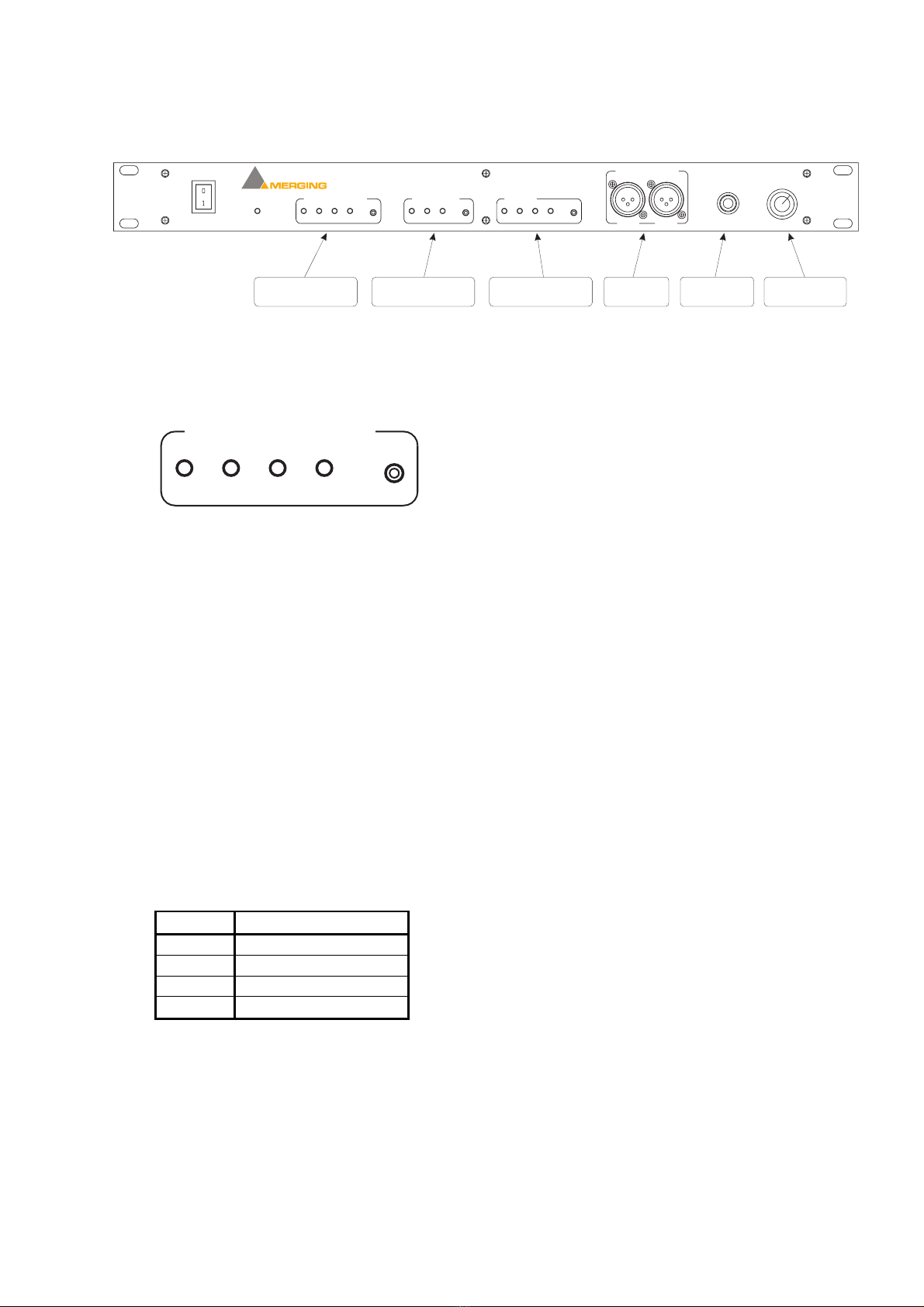
Chapter 2 – The Front Panel
MONITOR OUTPUTS
LEFT RIGHT PHONES VOLUME
MONITOR
SAMPLE RATE
7/85/6
3/4
1/2
32 44.1 48
REMOTE
POWER
dua II AUDIO INTERFACE
SYNCHRONIZATION
INT ODI AES WCL
Synchronization
Selection & Status
Sample Rate
Selection & Status
Monitoring
Selection & Status
Monitoring
Line Output
Monitoring
Phones Output
Monitoring
Volume Control
Synchronization Selector and Status
SYNCHRONIZATION
INT ODI AES WCL
The DUA II can operate in many different synchronization modes. It can synchronize to its internal clock or to a wide
range of industry standard external sources. Pressing the SYNCHRONIZATION button allows the selection of the
desired synchronization mode.
Possible Synchronization modes
• INT: DUA II synchronizes and locks to its internal clock.
• ODI: (Default) DUA II synchronizes to the optical input (ADAT). If no valid sync signal is present at the optical
input (when the ODI mode is selected), the ODI LED will light on RED. Once a valid sync signal has been
detected, the ODI LED will light on GREEN. If the sample rate of the DUA II and the ADAT signal are
identical, the selected sample rate LED will light on GREEN. The DUA II is now locked and synchronized to the
incoming ADAT signal.
• AES: DUA II synchronizes to an AES/EBU signal.
There are 4 AES/EBU sync modes. You can see which mode is selected by pressing the SYNCHRONIZATION
button for more than 1 second. The mode is then displayed in GREEN on RED background on the monitor LEDs
as follow:
MON LED AES/EBU sync mode
MON 1/2 AUTO DETECT
MON 3/4 AES/EBU Ref. Input
MON 5/6 AES/EBU 5/6 Input
MON 7/8 AES/EBU 7/8 Input
While in AUTO mode, the DUA II automatically detects and switches to a valid AES/EBU sync source.
In this mode, the LED MON 1/2 is light on GREEN, indicating the AUTO mode, and the automatically selected
input is indicated on the other MON LEDS in GREEN as well.
Press the MONITOR button to change the AES/EBU sync source mode.
Press the SYNCHRONIZATION button to save changes and return to the normal operation mode.
If no valid sync signal is present at the selected AES/EBU input (when the AES mode is selected), the AES LED
will light on RED. Once a valid AES sync signal has been detected, the AES LED will light on GREEN. If the
sample rate of the DUA II and the AES signal are identical, the selected sample rate LED will light on GREEN.
The DUA II is now locked and synchronized to the incoming AES signal.
© 2000 Merging Technologies DUA II User Manual 3
• WCLK: DUA II synchronizes to a Word-Clock signal (TTL or CMOS level square wave at the sample rate
selected on the front panel). If no valid sync signal is present at the Word-Clock input (when the WCLK mode is
selected), the WCLK LED will light on RED. Once a valid sync signal has been detected, the WCLK LED will
light on GREEN. If the sample rate of the DUA II and the Word-Clock signal are identical, the selected sample
rate LED will light on GREEN. The DUA II is now locked and synchronized to the incoming Word-Clock
signal.
Sample Rate Selector
SAMPLE RATE
32 44.1 48
DUA II supports 3 sample rates: 32 KHz , 44.1 KHz and 48 KHz.
The desired sample rate is selected by pressing the SAMPLE RATE button.
The sample rate is displayed in GREEN if DUA II is in internal or locked on the selected synchronization source.
The sample rate is displayed in RED if DUA II cannot lock on the selected synchronization source.
AutoDetect SR mode
By pressing the SAMPLE RATE button for 1 second, you enable the AutoDetect mode for the sample rate selection.
In this mode, the DUA II detects automatically the sample rate of the selected synchronization source.
While scanning the different sample rates, all 3 SR LEDs are light on RED.
When DUA II has found the sample rate of the selected synchronization source and is locked on it, the detected
sample rate LED light on GREEN.
When in sync mode INT:
In Normal ADAT mode, the DUA II selects the sample rate based on the ADAT signal returning from the device
connected and locked on DUA II.
In Stand Alone mode, the DUA II selects the sample rate based on the AES/EBU signal returning from the device
connected and locked on DUA II.
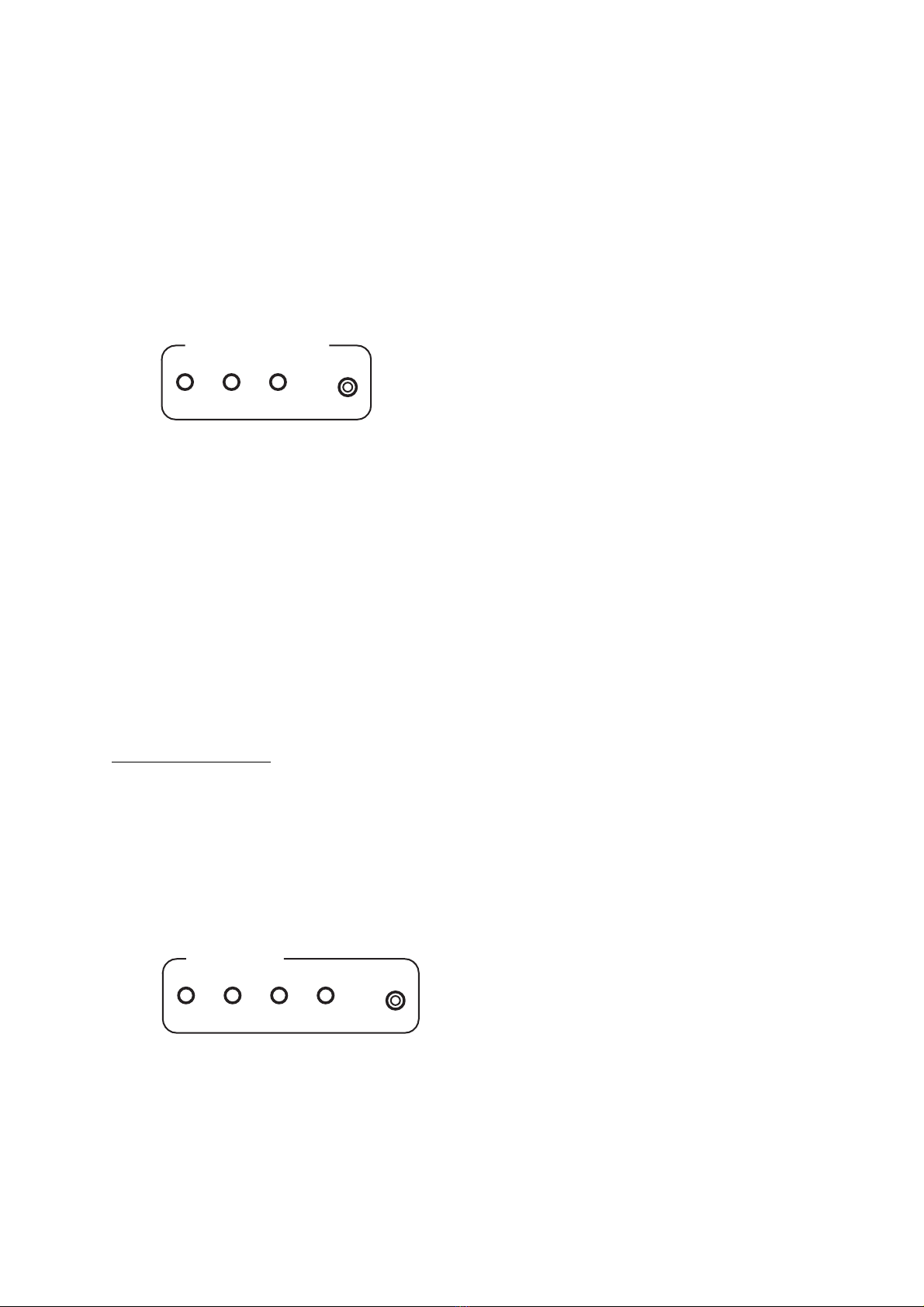
Monitoring Selector
MONITOR
7/85/6
3/4
1/2
This section allows for the Selection of any of the 8 input or output audio signals in pairs. The desired monitoring
source is selected by pressing the MONITOR button.
The monitoring source selected is displayed in RED for inputs (RECORD), or GREEN for outputs (PLAYBACK).

4 DUA II User Manual © 2000 Merging Technologies
Monitoring Outputs
MONITOR OUTPUTS
LEFT RIGHT PHONES VOLUME
Any professional level balanced audio input can be connected to the analog line monitor outputs of the DUA II.
4 output levels are selectable from consumer level (–10 dBV) up to professional level (+4 dBu).
See chapter 4 on how to configure the Analog Outputs Level.
The monitor outputs are also available on a stereo ¼ inch Jack connector with the volume control for a headphone.
Note: The volume control only impacts on the headphone monitoring, not on the XLR line outputs.
Power Switch & Remote indicator
REMOTE
POWER
The POWER switch toggles the power source on and off.
The REMOTE LED type indicator indicates whether the DUA II unit is in remote or local control.
It displays also an error status:
- If the LED is not lit, the DUA II is ready in local control mode.
- If the LED is lit on GREEN, the DUA II is ready in remote control. In this mode, the DUA II front panel controls
are being controlled via a software application (such as the Merging Pyramix Workstation).
- If the LED is lit on RED, the DUA II is not ready. The LED lights on RED at power-up for less than 1 second.
If the LED still light on RED ~1 second after power up, it means that DUA II is not working properly.
© 2000 Merging Technologies DUA II User Manual 5
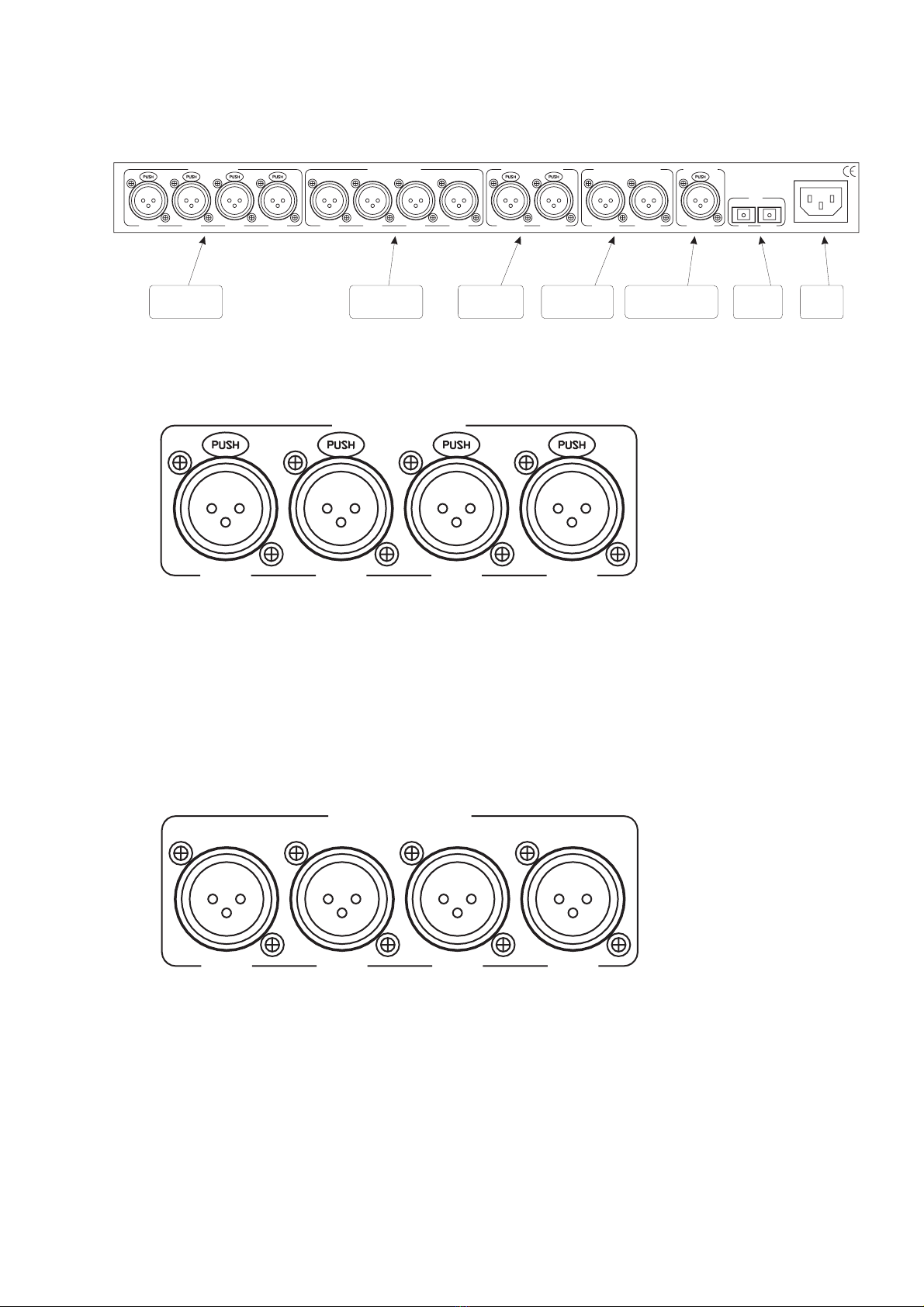
Chapter 3 – The Back Panel
LINE INPUTS LINE OUTPUTS AES/EBU INPUTS AES/EBU OUTPUTS AES-WC
CH 1 CH 2 CH 3 CH 4 CH 1 CH 2 CH 3 CH 4 CH 5/6 CH 7/8 CH 5/6 CH 7/8
ODI
IN OUT
REF IN
S/N :
Merging Technologies
Le Verney
CH 1604 Puidoux
Switzerland
100-250 VAC / 50-60 Hz
Analog line
Inputs 1-4
AES-EBU
Inputs 1-4
Analog line
Outputs 1-4
AES-EBU
Outputs 1-4
AES-EBU/WCL
Reference Input
ADAT
ODI I/O
Power
Supply
Analog Line Inputs 1-4
LINE INPUTS
CH 1 CH 2 CH 3 CH 4
Any professional level balanced audio outputs sources can be connected to the analog line inputs of the DUA II.
4 input levels are selectable from consumer level (–10 dBV) up to professional level (+4 dBu).
See chapter 4 on how to select the Analog Inputs Level.
The analog line inputs 1-4 are routed to the ADAT output channels 1-4.
Analog Line Outputs 1-4
LINE OUTPUTS
CH 1 CH 2 CH 3 CH 4
Any professional level balanced audio input sources can be connected to the analog line outputs of the DUA II.
4 output levels are selectable from consumer level (–10 dBV) up to professional level (+4 dBu).
See chapter 4 on how to select the Analog Outputs Level.
The analog line outputs 1-4 can be configured to output the ADAT input channels 1-4 or 5-8.
See chapter 4 on how to configure the Analog Outputs Routing.

6 DUA II User Manual © 2000 Merging Technologies
AES/EBU Inputs 5-8
AES/EBU INPUTS
CH 5/6 CH 7/8
Any professional level balanced digital AES/EBU audio output sources at 32, 44.1 or 48 KHz can be connected to the
AES/EBU inputs of the DUA II.
The AES/EBU inputs 5-8 are routed to the ADAT output channels 5-8.
AES/EBU Outputs 5-8
AES/EBU OUTPUTS
CH 5/6 CH 7/8
Any professional level balanced digital AES/EBU audio inputs at 32, 44.1 or 48 KHz can be connected to the
AES/EBU outputs of the DUA II.
The AES/EBU outputs 5-8 can be configured to output the ADAT input channels 1-4 or 5-8.
See Chapter 4 on how to configure the Digital Outputs Routing.
AES/EBU / Word-Clock Reference Input
AES-WC
REF IN
This XLR type connector has two functions. It can accept an AES/EBU sync reference or any Word-Clock signals.
When the DUA II is set to AES synchronization mode, it will resolve the DUA II clock to the AES/EBU sync signal
present here. When DUA II is set to Word-Clock synchronization mode, it will sync the DUA II clock to the Word-
Clock signal present here.

© 2000 Merging Technologies DUA II User Manual 7
ODI (Optical Digital Interface)
ODI
IN OUT
ODI IN
This EIAJ optical connector receives channels 1-8 of any ADAT compatible output.
ODI OUT
This EIAJ optical connector transmits channels 1-8 to any ADAT compatible input.
Power Connector
100-250 VAC / 50-60 Hz
DUA II uses universal power supply that accepts AC from 100 to 250 volts. It is designed to be connected to an outlet
that includes three pins (center pin to ground). The ground connection is an important safety feature designed to keep
potentially dangerous voltages away from the chassis. Never defeat the ground safety feature.
Never operate the DUA II with ungrounded outlets. Plugging the DUA II into an ungrounded outlet, or
defeating the ground pin, can create a potentially hazardous condition. Merging Technologies cannot be held
responsible for problems caused to DUA II or any associated equipment with improper AC connections.

8 DUA II User Manual © 2000 Merging Technologies
Chapter 4 – DIP Switch Settings
The DUA II contains a DIP switch which provides some extended configuration capabilities.
The DIP switch is accessible on the right side of the DUA II (looking from the front panel).
SW 1-2 Full Scale Analog Inputs Level
OFF-OFF + 6 dBu ( note 1 )
OFF-ON + 12 dBu
ON-OFF + 18 dBu ( note 2 )
ON-ON + 24 dBu
SW 3-4 Full Scale Analog Outputs Level
OFF–OFF + 6 dBu ( note 1 )
OFF–ON + 12 dBu
ON-OFF + 18 dBu ( note 2 )
ON-ON + 24 dBu
SW 5 Analog Outputs Routing
OFF Analog Outputs on CH 1-4
ON Analog Outputs on CH 5-8
SW 6 Digital Outputs Routing
OFF AES/EBU Outputs on CH 1-4
ON AES/EBU Outputs on CH 5-8
SW 7 ADAT Mode
OFF Normal ADAT mode
ON Stand Alone Mode
SW 8 Crystals Calibration
OFF Normal mode
ON Crystals Calibration mode
Default Factory settings are in bold.
Note 1: correspond to a -10 dBV nominal level, with headroom of 14 dB.
Note 2: correspond to a +4 dBu nominal level, with headroom of 14 dB.
© 2000 Merging Technologies DUA II User Manual 9
Chapter 5 – Typical Audio Connections
This section will display some typical audio connection scenarios for DUA II.
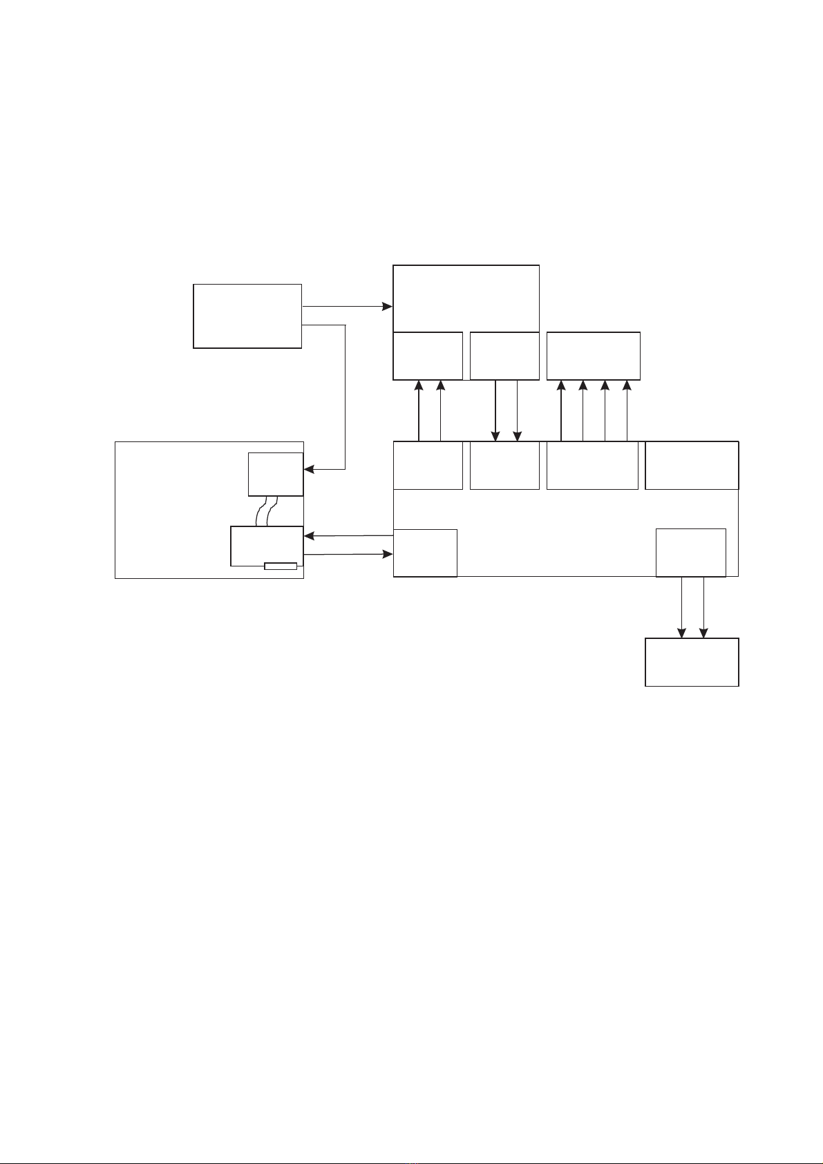
SOFTIMAGE®|DS 3.0 with SONY Digital BetaCam Users
This example is based on Digital Studio users who are using the DUA II in conjunction with the Merging Mykerinos
boards and a Digital Betacam video deck.
MY ERINOS
Card
VIDEO / TC
Bracket
SOFTIMAGE|DS
Computer
SONY
Digital Betacam
Video Deck
AES-EBU
INPUTS
AES-EBU
OUPUTS
Audio
Monitoring
MERGING DUA II
Audio Interface
AES-EBU
INPUTS
ADAT
ODI I/O
AES-EBU
OUTPUTS
ANALOG
OUTPUTS
ANALOG
INPUTS
Monitor
Outputs
Video Ref.
Black Burst
Generator
Audio
Monitoring/
Headphones
This example uses the following:
• Digital BetaCam outputs are routed through AES/EBU inputs of DUA II to DS input channels 1-4 (ADAT).
• DS output channels 1-4 (ADAT) are routed through AES/EBU outputs of DUA II to the Digital BetaCam inputs.
• DS output channels 1-4 (ADAT) are routed through analog outputs to the monitoring system.
(Alternate monitoring is provided by the front panel monitoring selection of DUA II).
• The Mykerinos card (via VIDEO/TC bracket) and the Video Deck are connected to the Video Ref. generator.
Note that each device should be connected to the video generator with its own cable.
Using the Loop-Through to connect the different devices is not recommended.
• The DUA II is set to ODI sync mode and AutoDetec SR mode.
• The DIP switch 1-8 must be set to: X – X – X – X – OFF – OFF – OFF – OFF.
10 DUA II User Manual © 2000 Merging Technologies
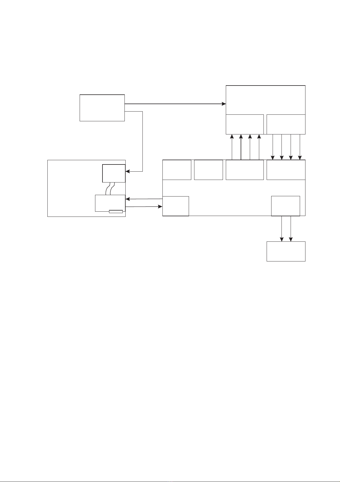
SOFTIMAGE®|DS 3.0 with SONY Analog BetaCam Users
This example is based on Digital Studio users who are using the DUA II in conjunction with the Merging Mykerinos
boards and an Analog BetaCam video deck.
Audio
Monitoring/
Headphones
ANALOG
INPUTS
ANALOG
OUTPUTS
MERGING DUA II
Audio Interface
AES-EBU
INPUTS
ADAT
ODI I/O
AES-EBU
OUTPUTS
ANALOG
OUTPUTS
ANALOG
INPUTS
Monitor
Outputs
MY ERINOS
Card
VIDEO / TC
Bracket
SOFTIMAGE|DS
Computer
Video Ref.
Black Burst
Generator
SONY
Analog Betacam
Video Deck
This example uses the following:
• Analog BetaCam outputs are routed through analog inputs of DUA II to DS input channels 1-4 (ADAT).
• DS output channels 1-4 (ADAT) are routed through analog outputs of DUA II to the Analog BetaCam inputs.
• The monitoring is provided by the front panel monitoring selection of DUA II.
• The Mykerinos card (via VIDEO/TC bracket) and the Video Deck are connected to the Video Ref. generator.
Note that each device should be connected to the video generator with its own cable.
Using the Loop-Through to connect the different devices is not recommended.
• The DUA II is set to ODI sync mode and AutoDetec SR mode.
• The DIP switch 1-8 must be set to: X – X – X – X – OFF – OFF – OFF – OFF.
© 2000 Merging Technologies DUA II User Manual 11
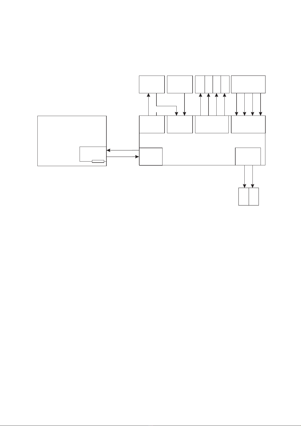
Merging®|Pyramix 3.0 Workstation with Surround Monitoring Users
This example is based on a typical Pyramix analog/digital audio studio with both types of devices and a surround
monitoring system.
MY ERINOS
Card
MERGING Pyramix 3.0
Computer
MERGING DUA II
Audio Interface
AES-EBU
INPUTS
ADAT
ODI I/O
AES-EBU
OUTPUTS
ANALOG
OUTPUTS
ANALOG
INPUTS
Monitor
Outputs
DAT/
Effect
CD
Player
Mixer /
Mic. Preamp.
LCR
S
W
S
L
S
R
This example uses the following:
• Mic.Preamp./Mixer outputs are routed through analog inputs of DUA II to Pyramix input channels 1-4 (ADAT)
• DAT/Effect/CD-Player outputs are routed through AES/EBU inputs of DUA II to Pyramix input channels 5-8
(ADAT)
• Pyramix output channels 1-4 (ADAT) are routed through analog outputs of DUA II to the monitoring system.
(In this example: CH1 = Left / CH2 = Center / CH3 = Right / CH4 = Subwoofer)
• Pyramix output channels 5-6 (ADAT) are routed through monitor outputs of DUA II to the monitoring system.
(In this example: Left = Surround Left / Right = Surround Right)
• Pyramix output channels 7-8 (ADAT) are routed through AES/EBU outputs of DUA II to the DAT/Effect.
(In this example: It may be a simple Stereo Mix to be recorded on DAT, or a send for external effect)
• The DAT/Effect must be synchronized to its AES/EBU input.
• The DUA II is set to ODI sync mode, AutoDetec SR mode and OUT5/6 monitoring.
• The DIP switch 1-8 must be set to: X – X – X – X – OFF – ON – OFF – OFF.
12 DUA II User Manual © 2000 Merging Technologies
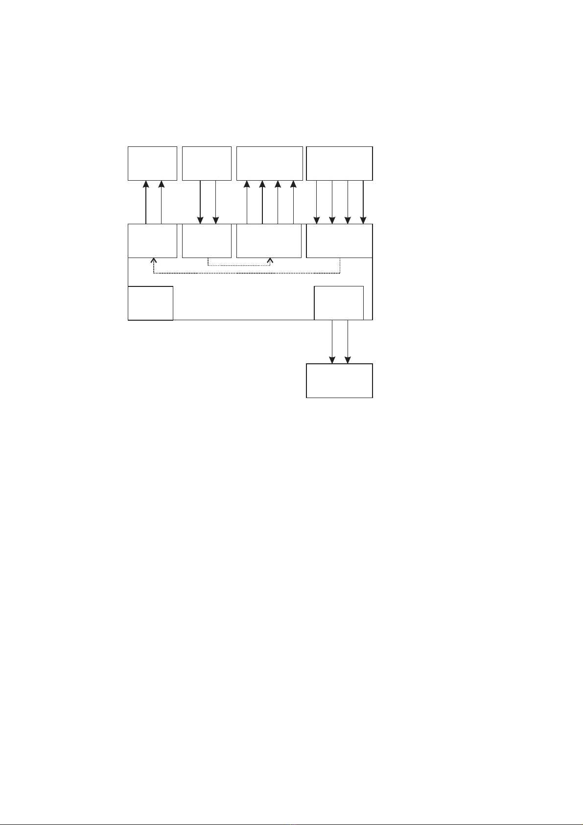
Stand Alone A/D and D/A Setup
This example is based on a stand-alone audio converter application.
This configuration allows having 4 ANALOG-to-AES/EBU and 4 AES/EBU-to-ANALOG converters.
MERGING DUA II
Audio Interface
AES-EBU
INPUTS
ADAT
ODI I/O
AES-EBU
OUTPUTS
ANALOG
OUTPUTS
ANALOG
INPUTS
Monitor
Outputs
4 Channels
Digital IN
4 Channels
Analog IN
Audio
Monitoring/
Headphones
4 Channels
Analog OUT
4 Channels
Digital OUT
This example uses the following:
• Analog line inputs 1-4 are internally routed to AES/EBU outputs 5-8.
• AES/EBU inputs 5-8 are internally routed to analog line outputs.
• The monitoring is provided by the front panel monitor selection of DUA II.
• The DIP switch 1-8 must be set to: X – X – X – X – ON – OFF – OFF – OFF.
© 2000 Merging Technologies DUA II User Manual 13
Appendix 1 – Technical Specifications
Parameter Conditions Value Unit
Dimensions 19" 1U height W = 485
D = 250
H =43
mm
Weight 1 Kg
Power Consumption 10 VA
Internal Sampling Frequency Accuracy 25° Celsius +/- 5 PPM
Internal Sampling Frequency Accuracy 0° to 50° Celsius +/- 25 PPM
Internal Sampling Frequency Jitter Measured on ODI output < 2 ns p-p
Analog Line Inputs
Parameter Conditions Value Unit
Resolution 24 Bits
Max. Sample Rate 48 KHz
Min. FS Input Level +6 dBu
Max. FS Input Level +24 dBu
Dynamic Range A-weighted 106 dB(A)
Unweighted 103 dB
THD+N 1 kHz @ -1 dBFS = 17 dBu -98 dB
Frequency Response 20Hz-20kHz ± 0.1 dB
Input Impedance Differential >20 KOhms
Common Mode Rejection >40 dB
Interchannel Isolation (Crosstalk) 1kHz >100 dB
Analog Line Outputs
Parameter Conditions Value Unit
Resolution 24 Bits
Max. Sample Rate 48 KHz
Min. FS Output Level +6 dBu
Max. FS Output Level +24 dBu
Dynamic Range A-weighted 103 dB(A)
Unweighted 100 dB
THD+N 1 kHz @ -1 dBFS = 17 dBu -94 dB
Frequency Response 20Hz-20kHz ± 0.1 dB
Output Impedance Differential <50 Ohms
Output Balance Ratio >40 dB
Interchannel Isolation (Crosstalk) 1kHz >100 dB
AES/EBU Inputs
Parameter Conditions Value Unit
Resolution 24 Bit
Max. Sample Rate 48 KHz
Input Impedance Differential 110 Ohms
AES/EBU Outputs
Parameter Conditions Value Unit
Resolution 24 Bit
Max. Sample Rate 48 KHz
Output Impedance Differential 110 Ohms
Note: All specifications subject to change without notice.
14 DUA II User Manual © 2000 Merging Technologies
Appendix 2 – Flow Chart Diagrams
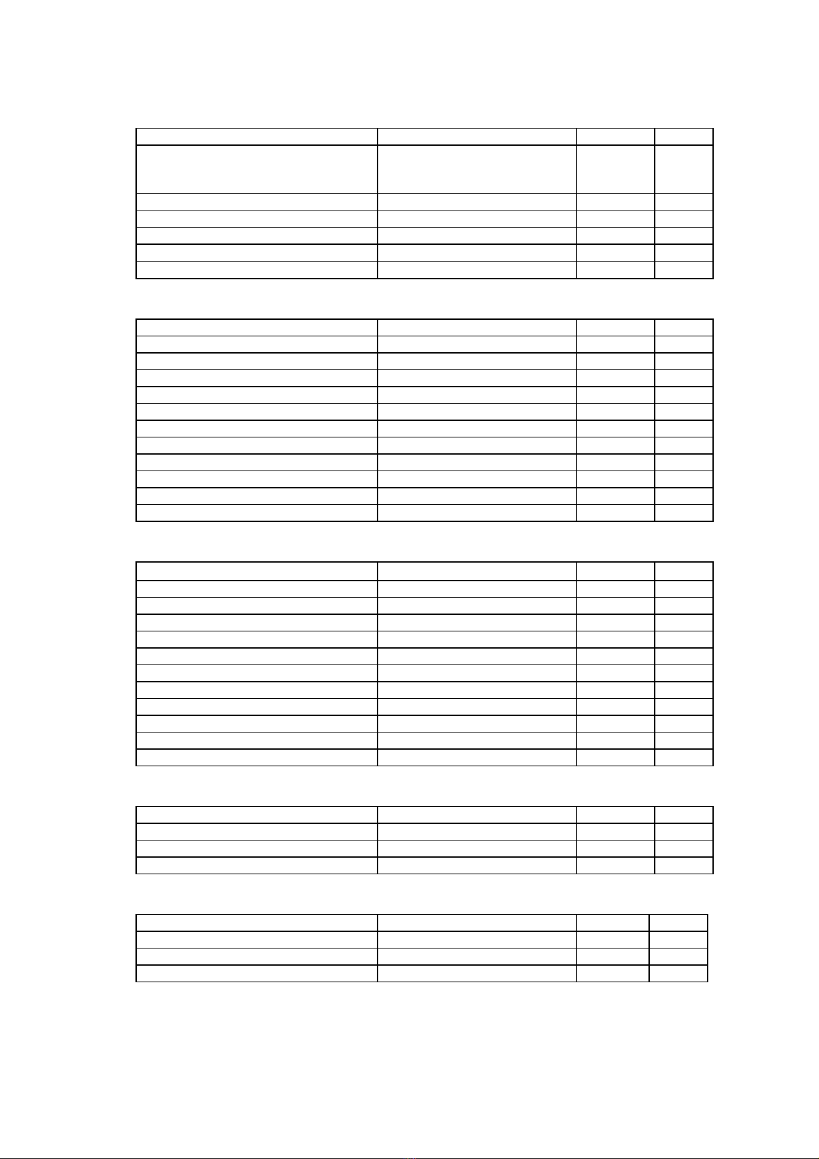
DUA II Synchronization Flow Chart
ODI
INT
AES-EBU
WCL
VCO
@512 FS
PLL
VCO
@ 512 FS
VCO
@512 FS
DIVIDER
256 FS
64 FS
LRCL
DUA II
Central Time Base
ADAT
Sync
Extractor
WCL
Sync
Extractor
Calibrated
Frequency
Generator
AES-EBU
Sync
Extractor
AUTO
SELECT
AES-EBU
IN 5/6
AES-EBU
IN 7/8
AES-EBU
REF. IN
/WLC
ADAT
ODI IN
MCL
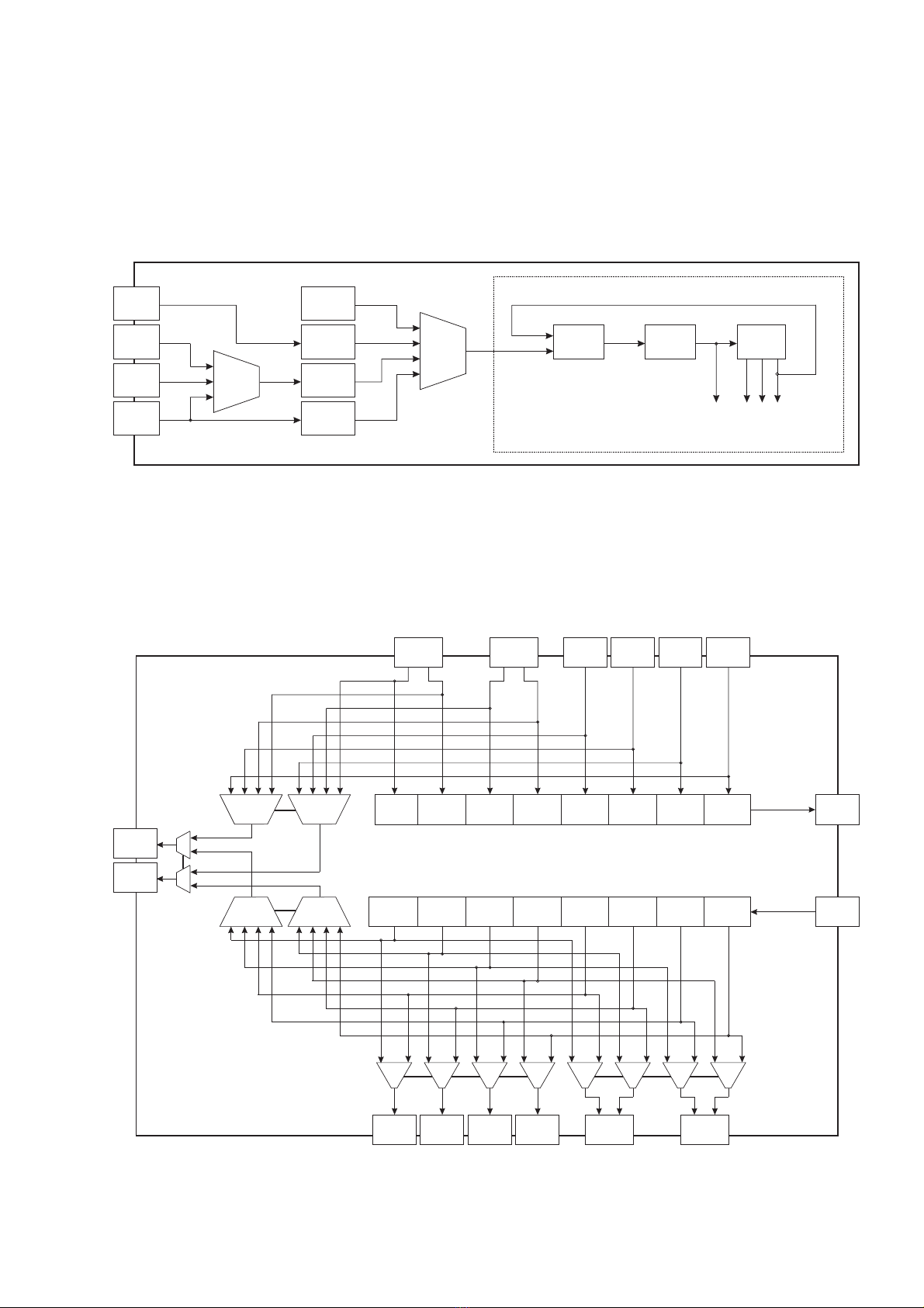
DUA II Audio Flow Chart
AES-EBU
IN 5/6
ANALOG
IN 4
ANALOG
IN 3
ANALOG
IN 2
ANALOG
IN 1
ADAT
CH 1
ADAT
CH 2
ADAT
CH 3
ADAT
CH 4
ADAT
CH 5
ADAT
CH 6
ADAT
CH 7
ADAT
CH 8
AES-EBU
IN 7/8
ADAT
ODI OUT
ADAT
CH 8
ADAT
CH 7
ADAT
CH 6
ADAT
CH 5
ADAT
CH 4
ADAT
CH 3
ADAT
CH 2
ADAT
CH 1 ADAT
ODI IN
ANALOG
OUT 1
ANALOG
OUT 2
ANALOG
OUT 3
ANALOG
OUT 4
AES-EBU
OUT 7/8
AES-EBU
OUT 5/6
1 / 5 2 / 6 3 / 7 4 / 8 1 / 5 2 / 6 3 / 7 4 / 8
2468
1 357
2468
1 357
MONITOR
LEFT
MONITOR
RIGHT
I
O
I
O
Table of contents
Other Merging Accessories manuals


