Meriam 5150 Series User manual
5150 Series HART
®
Communicator
USER’S MANUAL
9R253 B
January, 2014
Safety Information
Failure to follow all instructions could result in injury. Read, understand and follow all
safety warnings and instructions provided with this product. Also, meet or exceed your
employer’s safety practices.
In no event shall Meriam e lia le for any indirect, special, incidental, consequential or punitive damages
or for any lost profits arising out of or relating to any services provided y Meriam or its affiliates. It is not
possi le for Meriam to identify all foreseea le uses/misuses, therefore all persons involved in
commissioning, using or maintaining this product must satisfy their self that each intended application is
accepta le.
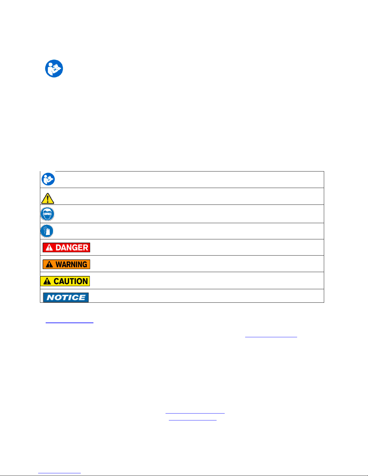
Safety Warnings
The ta le elow defines the safety sym ols, signal words and corresponding safety messages used in the
manual to identify potential hazards and are intended to warn persons a out hazards that could result in
personal injury or equipment damage.
This is the Read Instruction Manual sym ol. This sym ol indicates
that you must read the instruction manual.
This is the Safety Alert sym ol. This sym ol indicates a WARNING. Warnings alert you to actions that can
cause personal injury or pose a physical threat. Please read these carefully.
This is the Safety Glasses sym ol. This sym ol indicates that you must wear approved safety glasses during
the task.
This is the Safety Gloves sym ol. This sym ol indicates that you must wear approved safety gloves during
the task.
Indicates a potentially hazardous situation which, if not avoided, will result in death or serious
injury.
Indicates a potentially hazardous situation which, if not avoided, could result in death or
serious injury.
Indicates a potentially hazardous situation which, if not avoided, could result in minor or
moderate injury.
Indicates information essential for proper product installation, operation or maintenance.
Information in this document is su ject to change without notice. Check the Meriam we site
(www.meriam.com) for latest manual revision.
HART
®
is a registered trademark of the HART Communication Foundation www.hartcomm.org
For customer assistance please call your local Meriam representative or Meriam directly.
Meriam Process Technologies
10920 Madison Avenue
Cleveland, Ohio 44102
Telephone: (216) 281-1100
Fax: (216) 281-0228
E-mail: meriam@meriam.com
We : www.meriam.com

ATEX DOCUMENTATION
applies only to European Union countries.
GB
DK
I
E
NL
SF
P
F
D
SK
CZ
LT
LV
EST
PL
SLO
H
BG
RO

S
GR
M

5150 Series HART
®
Communicator
USER’S MANUAL
TABLE OF CONTENTS
Subject Page
5150 Series Communicator Overview........................................................................................................1
Touc screen Display Overview...........................................................................................................2
Display Layout ................................................................................................................................2
Keypad Layout.................................................................................................................................4
General Operation .....................................................................................................................................5
Power Button .......................................................................................................................................5
Backlig t..............................................................................................................................................5
Display Auto Dim Timer.....................................................................................................................5
Auto Standby Timer ............................................................................................................................5
Portable Operation / Battery Life.........................................................................................................5
PC Communication / Rec arging Cradle.............................................................................................6
Battery Pack Installation & Removal .................................................................................................7
Memory Card ......................................................................................................................................8
Kick Stand ...........................................................................................................................................8
External Connections ..........................................................................................................................9
Keyboard Functionality ....................................................................................................................10
Touc Keyboard Functionality..........................................................................................................12
Navigating t e communicator ..................................................................................................................14
System Menus....................................................................................................................................14
General.........................................................................................................................................14
Main.............................................................................................................................................17
System Setup...............................................................................................................................18
Language...............................................................................................................................19
Touc Screen Calibration......................................................................................................20
Date And Time Setup..................................................................................................................21
Power Management.....................................................................................................................22
HART
®
Setup .............................................................................................................................23
System Information .....................................................................................................................24
HART
®
Menu ....................................................................................................................................25
HART
®
Navigation Menu ...........................................................................................................26
Function Buttons..........................................................................................................................27
HART
®
Menu Pat ......................................................................................................................29
HART
®
Communication wit t e 5150 Communicator...........................................................................29
Overview............................................................................................................................................29
HART
®
Connections..........................................................................................................................29
HART
®
Communication....................................................................................................................31
Device Specific & Generic HART
®
Communication........................................................................ 32
Using Generic HART
®
Communications .......................................................................................... 32
Managing Device Configuration Files...............................................................................................33
Communication Troubles ooting ......................................................................................................34

Updating Software....................................................................................................................................35
Hazardous Area Use.................................................................................................................................35
Intrinsically Safe Operation ...............................................................................................................35
Returning for Repair.................................................................................................................................36
APPENDIX
Product Specifications ....................................................................................................................... 37
Safety Notices.................................................................................................................................... 38
Waste Electrical and Electronic Equipment (WEEE), Directive 2002/96/EC................................... 38
Spare Parts List.................................................................................................................................. 38
Intrinsic Safety Control Drawing....................................................................................................... 39
EC Declaration of Conformity........................................................................................................... 40
1
1.0 5150 Series HART
®
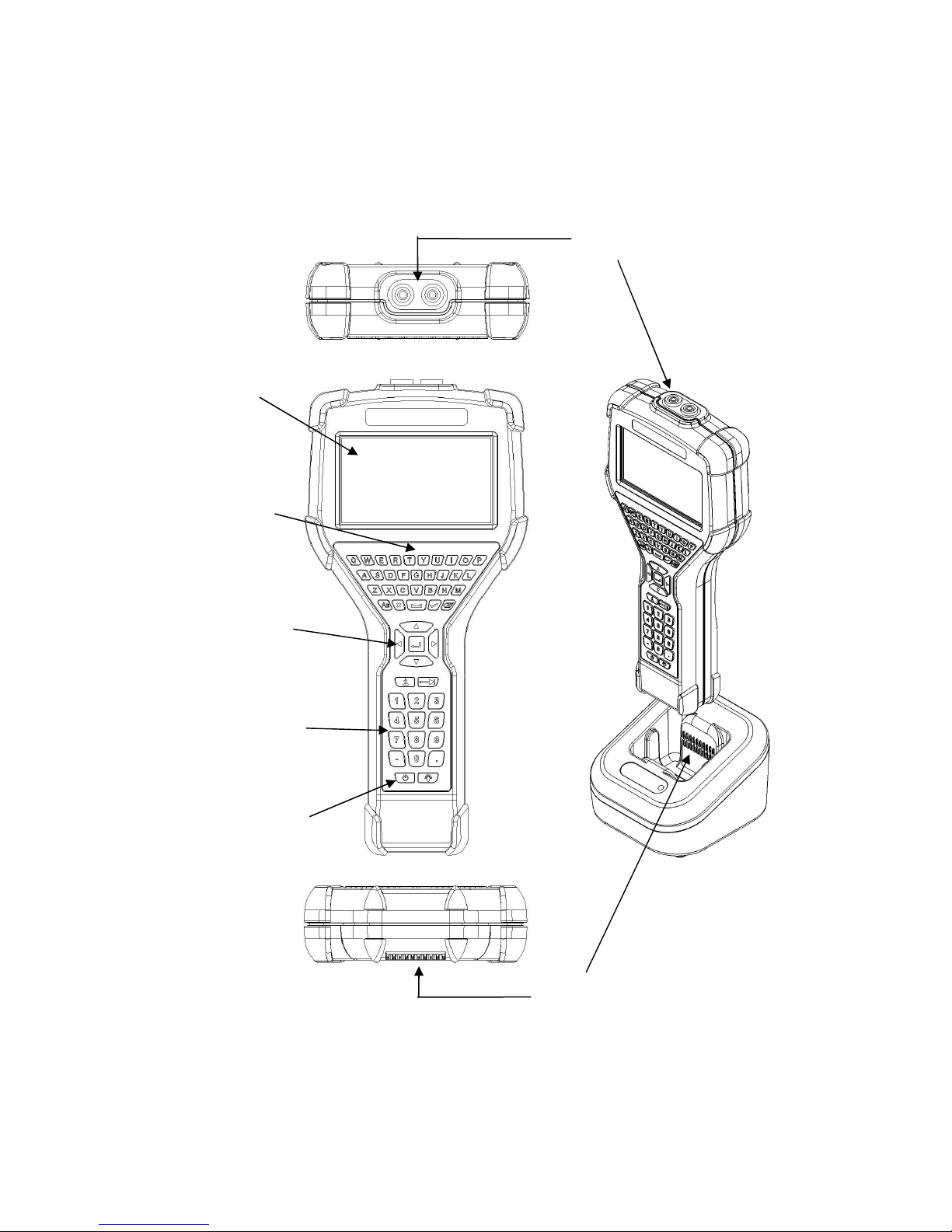
COMMUNICATOR OVERVIEW
T e 5150 Series HART
®
Communicator is a full function HART
®
Communicator supporting HART
®
communication Universal, Common Practice and Device Specific commands for commissioning,
configuration and maintenance operations.
C arging Cradle
Connections
Display and
Touc screen
Full QWERTY
style alp abetic
Keyboard
Navigation Keys
HART
®
Connections
Dedicated Numeric
Keypad
On/Off Key

2
1.1 TOUCHSCREEN DISPLAY OVERVIEW
T e communicator as a 4.3-inc widescreen backlit TFT color touc screen display wit 480 x 272
WQVGA pixel resolution. T e entire viewable area of t e screen is an active touc surface. T e touc screen
responds to and is optimized for finger presses (even t roug gloves). NO stylus is necessary. Never touc
t e screen wit s arp objects – simply use your finger.
Display Layouts
T ere are two styles of displays presented on t e communicator, system menu displays (Section 3.1) and
HART
®
menu displays (Section 3.2).
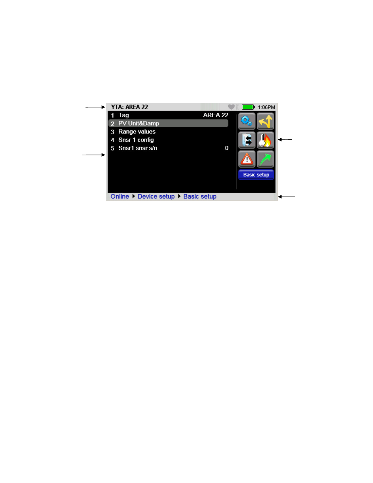
T e main system menu display is t e initial menu at power turn on. It is also accessible from any HART
®
menu (see Function Buttons in section 3.2). T ere are t ree distinct areas on t e system menus. T e top of
t e menu provides system information. T e middle of t e menu contains navigation icons to system actions
or new system menus. T e bottom of t e menu contains current HART
®
connection status and navigation
buttons.
Sample system display
System
Information
HART
®
Connections
and
Navigation
System
Navigation
Focus Pane
3
T e HART
®
menus are only accessible w en a HART
®
communication enabled device is connected and
communicating wit t e communicator. T ere are four distinct areas on a HART
®
menu. T e top of t e
menu provides information on t e currently attac ed device as well as various status indicators. T e middle
of t e menu is divided into two functional areas, HART
®
Menu Navigation and Function Buttons. T e
bottom of t e menu contains t e HART
®
Menu Pat .
c
Function
Buttons
Device and
Status Line
HART
®
Navigation
Menu
HART
®
Menu
Pat
Sample HART
®
menu display

4
1.2 Keyboard Layout
T e communicator provides a ig functionality keyboard, combined wit touc screen data keys, to
simplify data entry and navigation. Most tasks can be completed by just using t e dedicated keyboard. T e
touc screen keys (only visible during text data entry) add t e complete ISO Latin-1 (ISO 8859-1) c aracter
set, except numerals, in a large, easy to select key size.
Alp a Entry
Upper/Lower case Toggle
Cancel
Backspace
OK or Accept
Advance or Switc
(to next functional
area on screen)
Navigation Ring Enter or Select
Numeric Entry
(and Menu Accelerators)
Power
(Section 2.1) Backlig t
(Section 2.3)
Information
or Help

5
2.0 GENERAL OPERATION
2.1 Power Button
T e Power Button as four functions:
Power On – W enever t e communicator is in an “Off” state, pressing t e power key turns t e
communicator on. T is is a complete system start. T e communicator will execute a complete power op
sequence. Information regarding t e time and date is briefly displayed to allow t e user to verify t e
communicator’s readiness
.
Standby Operation – W en t e communicator is fully on, and t e power button is pressed briefly, t e unit
enters t e Standby state w ere allowed. In t is state t e display is off and most user input is ignored to
conserve battery power between uses. T e on-board computer maintains t e previous system state to
provided rapid recovery (Resume Operation).
Resume Operation - W en t e communicator is in Standby Operation, and t e power button is pressed
briefly, t e unit quickly resumes operation, returning to a fully “On” state of functionality at t e same menu
level t at was interrupted.
Power Off – W en t e communicator is fully on, and t e power button is pressed for t ree seconds, t e unit
will power down completely w ere allowed. T is conserves t e most battery power but requires a full
initialization w en t e unit is turned on again.
2.2 Backlight
T e Backlig t as 5 intensities from minimum to full Brig tness. T e user can select intensities by pressing
t e Backlig t Button. Backlig t intensity affects battery life. A lower intensity level will increase operation
time.
2.3 Display Auto Dim Timer
Display Auto Dim is a configurable mode t at allows t e user to minimize t e backlig t w en t ere is no
user or HART
®
activity detected by t e communicator for a user defined period of time. T is period is
adjustable using t e Display Auto Dim Timer. A s orter period will decrease battery consumption w en t e
communicator is not being used.
2.4 Auto Standby Timer
Auto Standby is a configurable mode t at allows t e user to automatically put t e communicator into a
standby state w en t ere is no user or
HART®
activity detected by t e communicator for a user defined
period of time. T e inactivity period is adjustable using t e Auto Standby timer. . In combination wit t e
Display Auto Dim Timer, s orter period will decrease battery consumption. T e standby timeout begins
w en t e Auto Dim Timer times out. If t e Auto Dim Timer is set to “Never” t e standby timeout will not
begin.
2.5 Portable Operation / Battery Life
T e communicator is powered by a rec argeable li-ion battery pack for portable operation. A full c arge
typically allows for 10 ours of continuous operation, or 200 ours of standby. See section 2.7 for
instruction on battery removal and replacement. Replacement battery packs are available from Meriam (PN
Z9A820).
6
T e battery pack contains an advanced battery fuel gauge t at actively monitors t e battery capacity and
t erefore does not require any “battery training” t roug out t e life of t e battery pack.
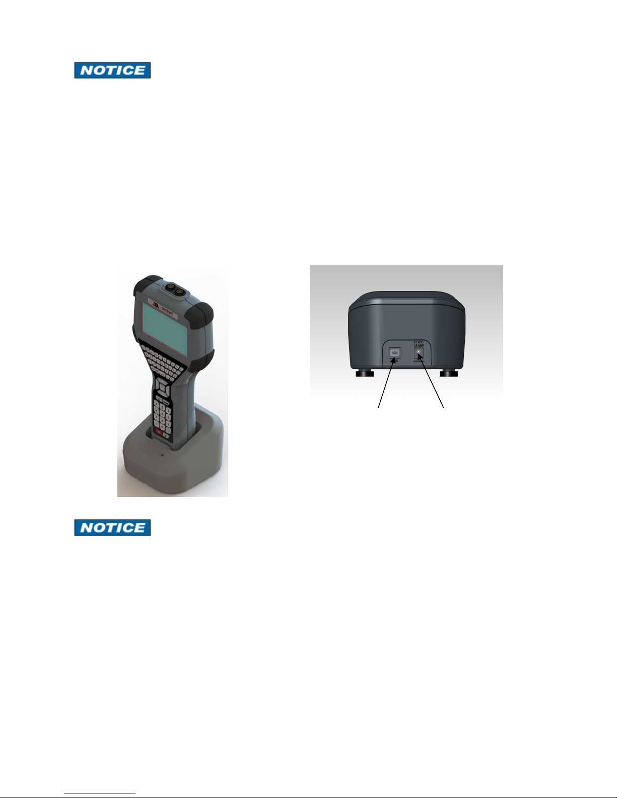
2.6 PC Communication / Recharging Cradle
T e Rec arging Cradle, included wit eac unit, automatically rec arges t e li-ion battery pack w en t e
communicator is properly inserted into t e energized cradle. To fully c arge a depleted battery pack takes
about six ours.
T e rec arging cradle also connects t e communicator wit a PC for file updates to t e communicator w en
it is properly inserted in t e cradle and a USB cable is attac ed from t e cradle to a PC wit t e wit t e
proper USB drivers and Meriam update package.
See section 5 for update instructions.
The Recharging Cradle is not intended to recharge a battery separately. To properly charge a battery
pack it is required to be inserted into a communicator prior to being placed on the charger.
Charging Indicator
T ere is a multicolor LED on t e rec arging cradle. T is LED indicates t e current c arging mode.
Off – No battery pack inserted, or power disconnected.
Solid Green – Battery is c arged.
Flas ing Amber – Battery is c arging.
Solid Amber – Battery temperature out of c arging range, c arge suspended.
Flas ing Red – Battery fault.
Solid Red –C arger fault.
5150 in c arging cradle
USB connection
to computer
Power connection
to AC adapter
Cradle Connection Details
Rear of cradle
7
The Recharging Cradle is not rated for intrinsic safety and should only be used in a non-hazardous area.
See the “Hazardous rea Use” section of this manual and the Intrinsic Safety Control Drawing in the
ppendix of this manual for more information.
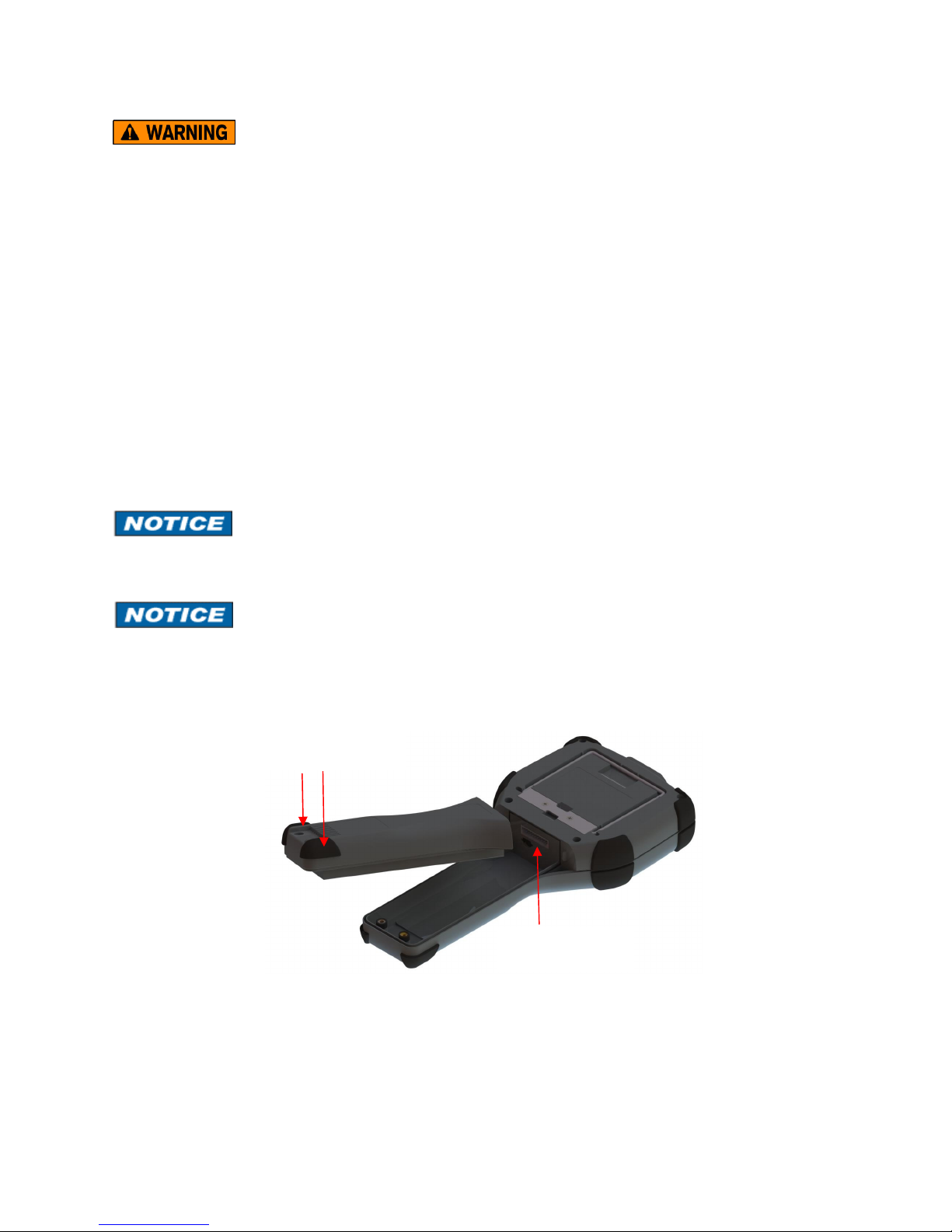
2.7 Battery Pack Installation & Removal
T e battery pack is eld into t e communicator by two standard 6-32 screws wit exagonal sockets t at
require a 7/64” ex key wrenc .
To install t e battery pack set t e communicator enclosure wit t e display downward on a flat stable
surface. Rest t e battery pack in t e battery pack compartment of t e enclosure leaving a ½” gap between
t e battery pack and t e connector on t e communicator enclosure. Slide t e battery pack upward along t e
enclosure until t e connectors mate completely and t e screws are aligned wit t e t readed inserts on t e
communicator body. T read t e screws into t e insert to complete t e installation.
For disassembly, reverse t e order of t e operations.
Over-tig tening t e battery case screws w en assembling can cause damage to t e communicator.
Maximum torque s ould not exceed seven in-lb.
Battery s ould be c arged completely (10 ours) before using t e communicator t e first time. See Section
2.9 for detail on using t e c arging cradle.
Battery pack
removal
6-32 screws wit
7/64” exagonal socket
µSD memory
card access
8
2.8 Memory Card
T e communicator is s ipped standard wit a µSD memory system card. T e system card is used for storage
of required software, software updates, HART
®
DD files and device configuration files. It is not intended for
use unrelated to t e operation of t e communicator. W en t e µSD memory system card is in t e 5150, t e
user as no access to t e card except wit t e Meriam provided PC software.
T is card s ould only be replaced by Meriam part Z9P780, or its successor, and only under t e direction of
Meriam personnel. Use of a non-system memory card will void safety certifications.
To access t e memory card, follow t e Battery Pack removal instructions.
To remove t e memory card - Once t e battery pack as been removed, press gently on t e memory card to
unlock it from t e card older. Carefully remove t e memory card from t e enclosure ( Note: tweezers or
small needle-nose pliers can be elpful in removal and insertion).
To replace t e memory card – Insert t e memory card carefully into t e card older, contacts toward t e back
of t e communicator and card label towards t e front (screen side) of t e communicator. Be sure t e
memory card is resting in t e older before releasing it. Gently press t e card into t e older to lock it into
place. Replace t e battery pack and secure it to t e communicator enclosure.
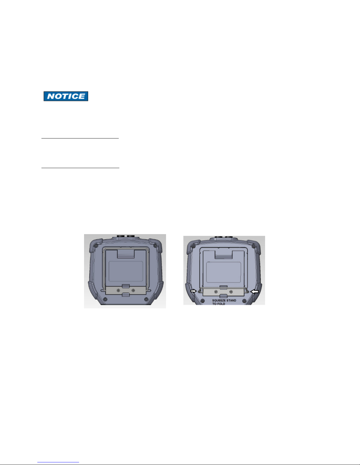
2.9 Kick Stand
T e communicator is equipped wit a kick stand to provide a better viewing angle. T e stand latc es in t e
down/open position. To return t e kick stand to t e up/closed position squeeze t e base inwards from bot
sides to unlatc it.

9
2.10 External Connections
Loop Communication Jacks / Lead Set – All models are equipped wit a standard size banana jack on
0.75” center. T e lead set supplied wit t e communicator as a standard banana plug on one end and mini-
grabbers on t e ot er for convenient connections.
For Intrinsically Safe model 5150X, verify the instruments in the loop are installed in accordance with
intrinsically safe field wiring practices before making connection from the field device to the Unit’s loop
communication jack. See the Hazardous rea Use Section of this manual and the Intrinsic Safety
Control Drawing in the ppendix for more information.
Charging Cradle
Connector
Eac unit as an electrical connector located at t e bottom of t e and eld. T e connector provides fast and
secure connection to t e Communication / c arging cradle supplied wit eac and eld. Seat t e connector
end of t e communicator into t e c arging cradle wit t e front of t e communicator facing t e front of t e
c arging cradle. Inserting t e communicator into an energized cradle begins t e c arge cycle and allows
communication wit a PC. See section 5 for update instructions.
The Recharging Cradle is not rated for intrinsic safety and should only be used in a non-hazardous area.
See the “Hazardous rea Use” section of this manual and the Intrinsic Safety Control Drawing in the
ppendix of this manual for more information.

10
2.11 Keyboard Functionality
T e keyboard is logically arranged into four areas based on t e frequency of use. T e alp a and fixed
function keys will be used less frequently t an t e navigation and numeric keys.
T e alp a keys contain all 26 c aracters of t e ISO basic Latin alp abet. T ey are arranged in t e same
order as a standard QWERTY keyboard. T e alp a keys are used for text data entries as well as exadecimal
(A to F) numeric data entries. W en not entering data t ese keys are ignored.
Alp a &
Decision
Navigation &
Information
Numeric
Fixed
Function
11
Decision keys ( ard key) are active w en decision buttons appear on t e screen. T eir function is duplicated
by t e decision buttons (touc screen button). Decision keys are also used for some auxiliary functions. See
sections 3.2 (Create s ortcuts) for detail.
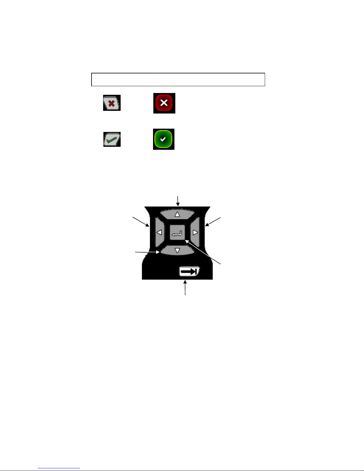
Navigation keys are used to move focus around t e display and to select t e item t at is in-focus.
Information key provides on-screen elp w en available.
Numeric keys are used for text or numeric data entries.
Numeric keys are also used as accelerators to advance menus and initiate actions w en indicated by t e on-
screen icons.
T e Fixed Function keys were discussed in Section 2.1 and 2.3
=
=
KEY BUTTON DECISION
CANCEL/ESC
ACCEPT
Move focus up
Move
focus left
Move
focus rig t
Move focus
to next pane
Move
focus down Select/Enter
in-focus
menu item
12
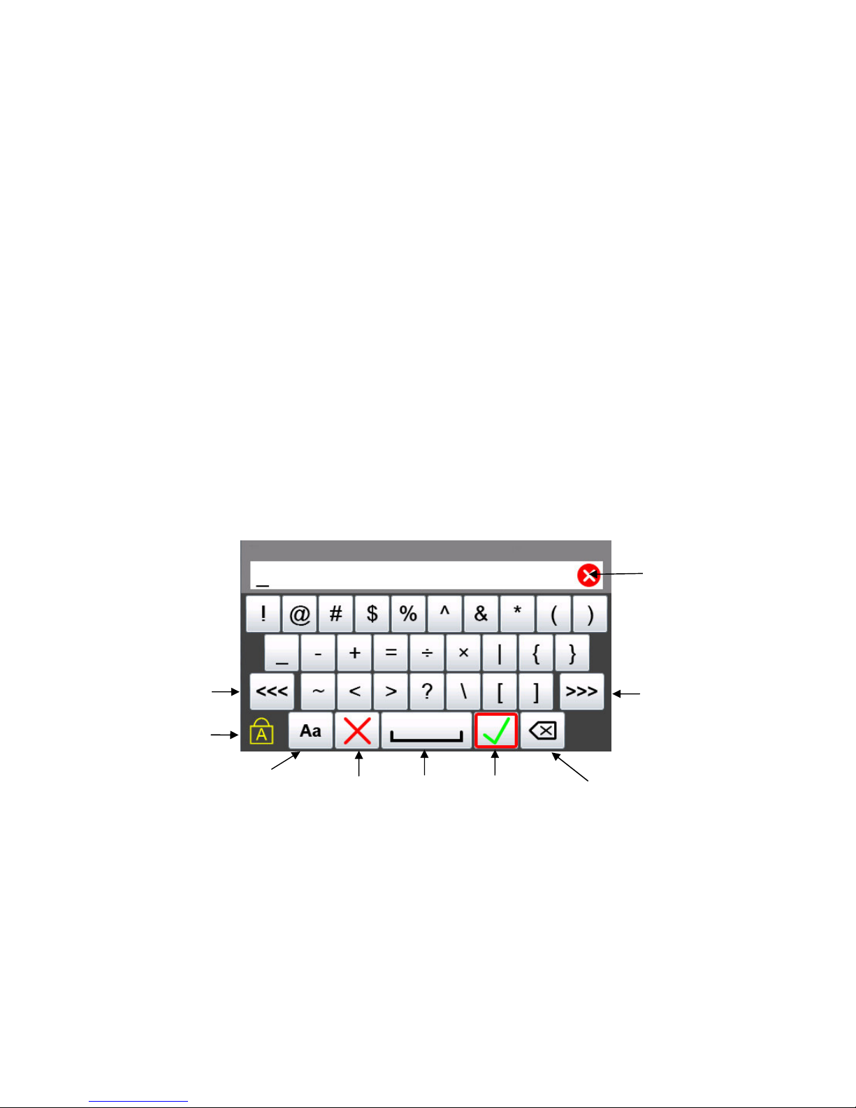
2.12 Touch Keyboard Functionality
T e 5150 Series and HART
®
communication support t e ISO Latin-1 (ISO 8859-1) c aracter set for most
text data entry. T is c aracter set contains 191 c aracters. Of t ese c aracters 65 are available on t e
communicator main keyboard. T e remaining c aracters, and duplication of t e ISO basic Latin alp abet
(lower + upper case) are available from t e touc screen. W enever a text edit window appears t e touc
keyboard is visible too. T ere are multiple keysets to allow larger keys, improving usability. Since t e ISO
basic Latin alp abet c aracters are available from t e dedicated keyboard, t ey are t e last touc keyset. T e
touc keys are grouped by language usage w erever practical, and keysets are ordered based on estimated
usage. T e first touc keys t at are visible are commonly used symbols. To move to ot er keysets use t e
“<<<” and “>>>” touc keys. Upper/Lower case selection (Cap Lock) does not affect keyset #1 or keyset
#2 (symbols). Navigation of t e keys on t e text edit display is by touc screen or t e Navigation Key set.
A red box surrounding t e key signifies t at t e key as focus. Some text data parameters (“tag” for
example) do not support t e full ISO Latin-1 (ISO 8859-1) c aracter set. W en t is is t e case, t e non-
functional touc screen c aracters will be gray. Since t ese data types do not support lower case alp a
c aracters, be sure t e “Key Caps Locked” symbol is present, or t e alp a ard keys will appear not to
function. W en t e c aracters entered in t e edit box reac t e string size limit for a specific parameter, t e
cursor disappears, a yellow block appears after t e last c aracter and additional c aracter entry is ignored.
For example, “tag” is limited to eig t c aracters. If t e lengt of t e data entry exceeds t e field size on t e
screen t e c aracters can be s ifted left or rig t by sliding your finger in t e data field. Data entry always
s ifts t e c aracters full left so t e end of t e entry is visible.
Navigate to
Previous
keyset
Navigate to
Next
keyset
Key Caps
Locked
Keyset #1
Cancel Space Accept
Select
Upper/lower
case
Backspace
Clear
Edit Box

13
Keyset #2
Keyset #3 (upper case)
Keyset #3 (lower case)
Keyset #4 (upper case)
Keyset #5 (upper case)
Keyset #4 (lower case)
Keyset #5 (lower case)

14
3.0 Navigating the Communicator
3.1 System Menus
System menus are used to access information and settings relating to t e operation of t e communicator.
System Menus – General
System Information
T e top of t e system menus contain system information. T is field is not navigable.
Communicator Information – Specifies t e communicator model on t e main system menu.
Communication Status – Displays if HART
®
communication is active, w et er t ere are any ot er master
( ost) devices active, and if t ere is a burst mode device active (see HART
®
Menus for more detail
3.2.1).
Focus Pane - T e focus pane is used in every system menu to indicate w at
icon will be selected w en t e Select Key is pressed. Focus is c anged by
use of t e Arrow Keys. Select Key and t e Arrow Keys are part of t e
keyboard navigation ring.
Navigation Number – T e navigation number at t e upper rig t of eac
icon indicates w at icon will be selected w en t e corresponding
c aracter on t e keyboard is pressed. T e focus pane does not need to
be surrounding t e button for t e action to occur. T e focus pane will
be on t e item w en returning to t e menu.
THREE WAYS TO NAVIGATE
Touc screen – T e communicator is equipped wit a touc screen.
Simply touc t e icon on t e menu to select t e icon action. T e
focus pane does not need to be surrounding t e button for t e action
to occur. T e focus pane will be on t e item w en returning to t e
menu.
Communicator
in
formation
communication
status
Battery Status
Current time
Other manuals for 5150 Series
1
Table of contents
Other Meriam Cell Phone manuals


