Meris MERCURY X User manual


SECTION 1 PG. 1 - 2 OVERVIEW
- MercuryX
- Navigation Controllers (C1, C2, C3)
- Highlighted Features
- Back Connections
SECTION 2 PG. 2 PRESET PAGE
SECTION 3 PG. 3 EDITING (EDIT PAGE)
- EDIT PAGE - Navigation Controllers, Favorited Parameters
- UI Map in GRAPHIC VIEW
SECTION 4 PG. 5 SAVING (SAVE AS PAGE)
- SAVE AS PAGE - Navigation Controllers, Save, Quick Save, Selecting Fields
- 2 FAVORITE PARAMETERS
- SAVE PRESET or CANCEL
- COPYING A PRESET
- QUICK SAVE
SECTION 5 PG. 8 FAVORITES BANK
SECTION 6 PG. 9 MODIFIERS
SECTION 7 PG. 12 EXPRESSION
SECTION 8 PG. 14 PREDELAY
SECTION 9 PG. 15 REVERB STRUCTURES
SECTION 10 PG. 16 CATEGORIES AND ELEMENTS
- Preamp Category
- Filter Category
- Pitch Category
- Modulation Category
TABLE OF CONTENTS

SECTION 1 1 PG. 21 MIDI CC TABLE
SECTION 1 2 PG. 26 TUNER
SECTION 1 3 PG. 26 GLOBALS
SECTION 1 4 PG. 28 TEXT VIEW (ALTERNATIVE VIEW OF EDIT PAGE)
SECTION 1 5 PG. 28 EXPORTING PRESETS
SECTION 1 6 PG. 28 FACTORY RESET
SECTION 1 7 PG. 29 FIRMWARE UPDATE
SECTION 1 8 PG. 29 GLOSSARY
SECTION 1 9 PG. 32 TECHNICAL SPECIFICATIONS

1
TRANSCEND TO NEW WORLDS
MercuryX takes the heart and soul of Mercury7 and expands it far beyond sci-fi into the highest quality and most flexible studio
reverb ever created in a pedal format. All of our passion for pro audio has made it into both the algorithms and hardware
performance of this pedal. MercuryX combines 8 custom Meris reverb algorithms and incorporates those into a modular system
UI/architecture that we first introduced with the award winning LVX pedal. To make this complex system immediately intuitive to
navigate, we again leveraged the simple and easy to use UI first developed for LVX. Exploring the factory presets (and pressing the
HOLD MODIFIER) will be your gateway into experiencing the power and flexibility within this instrument. As you discover all of the
new ways to create with MercuryX, your own sonic visions will be unveiled.
MercuryX features 8different reverb structures. Ultraplate and Cathedra are from Mercury7 and are inspired by the moody sci-fi
reverbs featured in Blade Runner. The 78 Room, 78 Plate and 78 Hall structures are inspired by the venerable sounds of a studio
classic with the decay time controlled by an EQ network. Spring, Prism, and Gravity are brand new structures unique to MercuryX.
See Section 9 for details.
01 - OVERVIEW
IS A MODULAR REVERB SYSTEM WITH PRO AUDIO & STUDIO RACK
HERITAGE, ADVANCED PROCESSING, AND HIGH PERFORMANCE SIGNAL PATH.
78 HALL (HIFI)
78 PLATE (HIFI)
ULTRAPLATE (MERCURY7)
78 ROOM (HIFI)
GRAVITY CATHEDRA (MERCURY7)
SPRING
PRISM
2
CANYONERO QUICKSTART GUIDE
99
PRESETS
MIDI
IN/OUT
EXPRESSIVE
HOLD SWITCH
TUNER
PRECISION
MODULAR
STUDIO REVERB PROCESSING
STEREO
FIRST GLANCE
Canyonero is a modular delay system with pro audio heritage, advanced processing, and high performance signal paths.
Turn knob to navigate presets.
Push to edit preset parameters,
turn to navigate parameter pages.
Hold to enter save mode.
1.
2.
3.
4.
5.
6.
7.
THE NEW GENERATION OF PEDALS
*Download full PDF manual on product site.
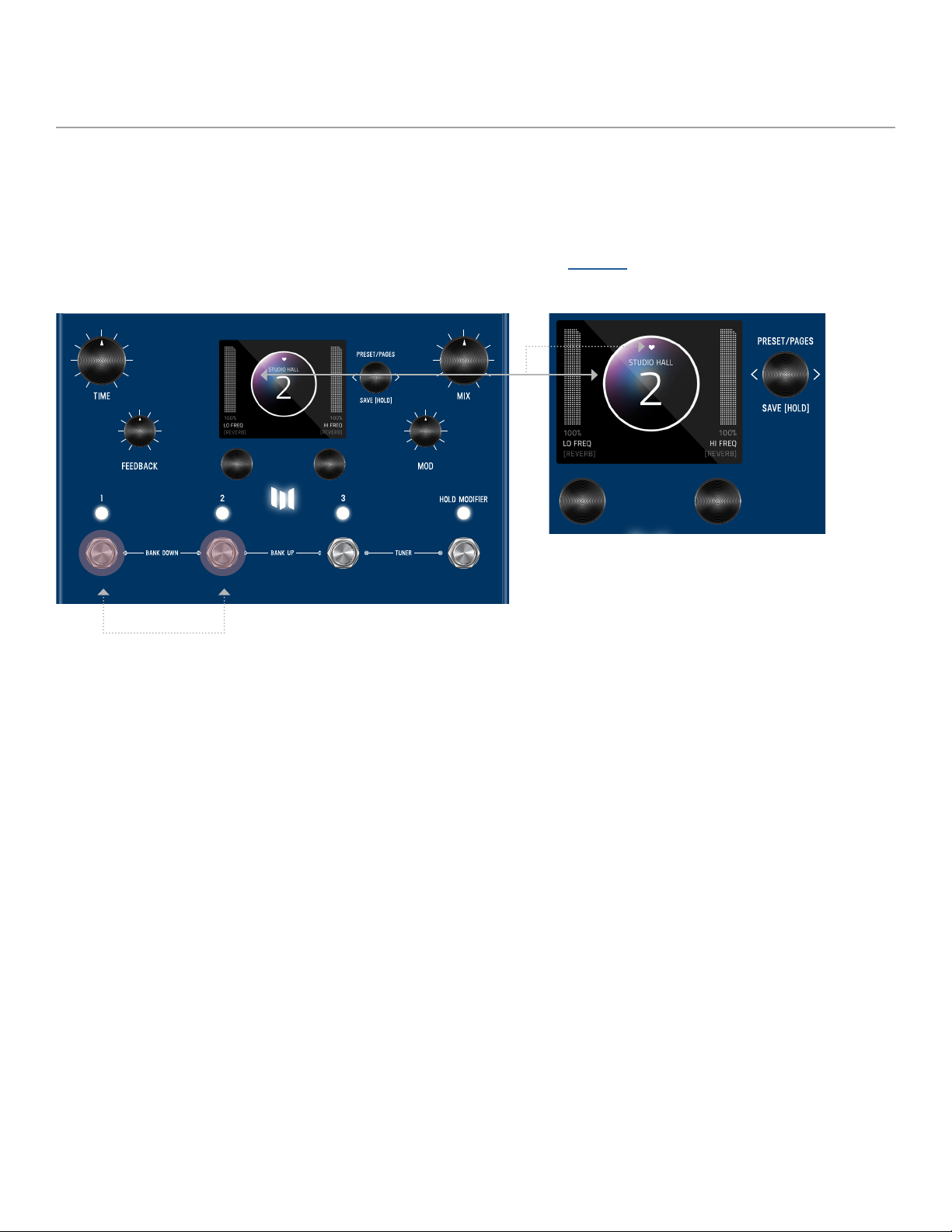
Turn knob to edit current
parameter.
3 knobs are your navigation controllers.
Turn knob to edit favorite parameter.
CONTROLLER 1 (OR C1)
CONTROLLER 2 (OR C2)
CONTROLLER 3 (OR C3)
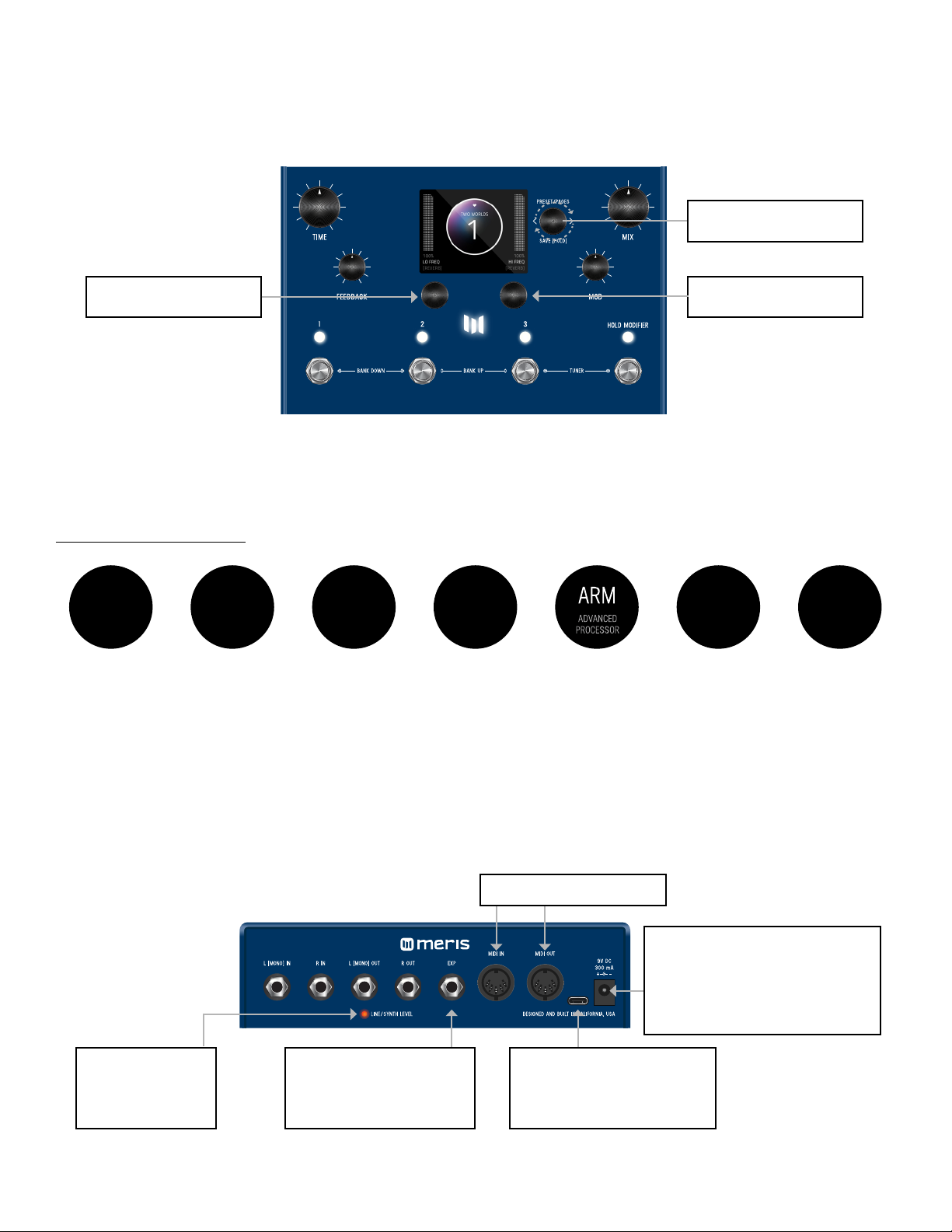
7 HIGHLIGHTED FEATURES
3 MAIN CONTROLLERS: C1, C2, C3
BACK PANEL CONNECTIONS
When using MercuryX, 3 knobs are your main navigation controllers: C1, C2, C3.
The other four knobs are your top level controls for DECAY, PREDELAY, MOD, and MIX.
CONTROLLER 1 (OR C1) CONTROLLER 2 (OR C2)
CONTROLLER 3 (OR C3)
POWER SUPPLY
9VDC center-negative power and
at least 300mA of current to the
2.1mm power input required.
USB-C
Used to connect to computer
for firmware updates only.
EXPRESSION PEDAL JACK
Realtime control of multiple
parameters simultaneously.
LINE/SYNTH LEVEL
Indicator LED is lit
when enabled.
5 PIN DIN MIDI I/O JACKS
3
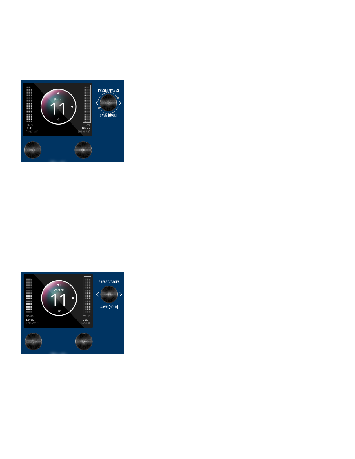
03- EDITING (EDIT PAGE IN GRAPHIC VIEW)
EDIT PAGE
From the PRESET PAGE, push C3 to enter EDIT PAGES. The EDIT PAGE is where you select categories and change parameters
within each preset. The middle bubble is your category. Turn C3 to cycle through categories. Turn C1 knob to carousel through the
parameters. The colored bubble is your selected parameter within each category. Turn C2 to edit the selected parameter.
Turn C3 knob to cycle through blocks.
Colored sphere indicates
selected parameter
CONTROLLER 2 (OR C2)
Value of the selected (colored) parameter
(top L sphere). Turn C2 to change value.
CONTROLLER 1 (OR C1)
Turn C1 knob to carousel through the
parameters
Category
02
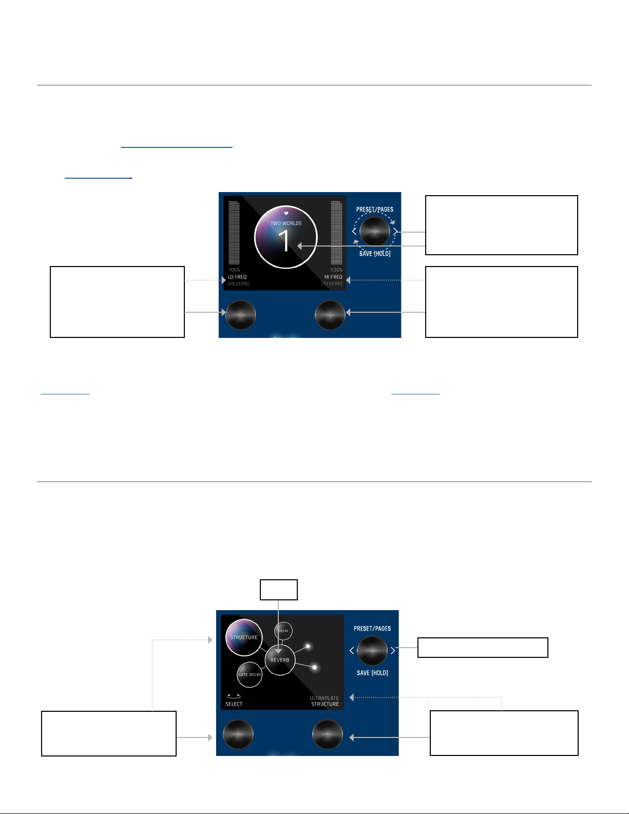
When you first power up MercuryX, you will enter the Preset Page. By default, MercuryX is shipped in “GRAPHIC VIEW”. In
GRAPHIC VIEW, 3 knobs are your navigation controllers: C1, C2, C3. The Preset Page consists of a preset bubble that contain the
name and number. 2 FAVORITE PARAMETERS are controlled by C1 and C2 (located directly above the controllers).
(You can assign your favorite parameters per preset, to either the L or R side. Changes of the 2 favorited parameters are located
in the SAVE AS PAGE. Details ahead.
CONTROLLER 2 (OR C2)
Turn C2 knob to edit
favorite parameter assigned
to the R side.
CONTROLLER 3 (OR C3)
Turn knob to navigate thru
1-99 presets (33 banks of 3).
- PRESET PAGE (GRAPHIC VIEW)
CONTROLLER 1 (OR C1)
Turn C1 knob to edit favorite
parameter assigned
to the L side.
NOTE: GRAPHIC VIEW is designed to focus on 1 block and/or 1 parameter at a time per preset. (You have the option to switch to
“TEXT VIEW” in GLOBALS -> EDIT PAGE. Favorite Parameters are also available in TEXT VIEW.

4
UI MAP - (IN GRAPHIC VIEW)
TACTILE PAGE
Preset Page - (Home)
From Preset Page, push C3 to
go to Edit Page. Turn C3 to
navigate thru 2nd level.
Tactile Page
Edit Pages - 2nd level
(software + bundle version)
Globals
From the PRESET PAGE (home), push C3 to navigate into the EDIT PAGES (2nd level). The 2nd level, consists of EDIT PAGES,
GLOBALS, SYSTEM INFO and TACTILE PAGE that wrap around when turning C3.
Turn knobs for DECAY, PREDELAY, MOD or MIX any time while editing, and the Tactile Pop-Up View (for detailed values) will
temporarily show. (You can also turn “OFF” or disable the Tactile Pop-Up View in Globals) To have the TACTILE PAGE in persistent
view, push C3 from PRESET PAGE, then turn C3 L from EDIT PAGE.
SYSTEM INFO

5
04- SAVING (SAVE AS PAGE IN GRAPHIC VIEW)
SAVE AS PAGE
Favorites (for Favorite Bank)
Preset Name
Preset Number
“Edited” icon displays when
any changes are made to a preset
Once edits are made within a preset, hold down C3 knob to enter SAVE AS PAGE. Sphere will change color.
You can change the name, change the preset number, select/deselect if this is one of up to 3 favorite presets (for the FAVORITES
BANK located before Bank 1) and assign your 2 favorite parameters on either the L or R side of the screen (located directly above
C1 and C2).
The name edit field will always be selected first when you enter the SAVE AS PAGE. Use C3 to select fields. You can navigate
fields within the bubble and to the L and R parameter. The field selection order when turning C3 R starting from the name field is:
name -> number -> L favorite parameter -> R favorite parameter -> heart (for favorite bank).
GLOBALS
SELECTING FIELDS
Globals is located at the end of the Edit Page, after you cycle thru all categories. A shortcut to Globals is to start from Edit Page
and turn C3 L. Globals is before System Info. Globals carousels the same way as the Edit Page but will be colorized in solid gold.
CONTROLLER 1 (OR C1)
Turn C1 knob to select.
Push C1 to insert character (for naming)
Hold C1 to clear all naming
CONTROLLER 2 (OR C2)
Turn C2 knob to edit selected field.
Push C2 to skip to character type for naming:
letters, numbers, and symbols.
CONTROLLER 3 (OR C3)
Once you enter this SAVE AS PAGE by holding down
C3 knob, turn C3 to skip to each field
Press C3 to delete character (for naming)
6
2 FAVORITE PARAMETERS can be assigned to each preset. They are located on each side of the preset bubble, directly above C1
and C2. In the SAVE AS PAGE, turn C3 to select either the L or R field. The field will highlight as an outlined box AND a dot will
appear on either side of the preset bubble to indicate which side is selected. Turn C1 or C2 to change parameter. HOLD C3 to
save your assigned favorite parameter.
In the EDIT PAGE, if a parameter was assigned as a FAVORITE PARAMETER, a filled in L or R dot will appear to remind which side
it was assigned.
Favorite parameters can also be quickly assigned to C1 or C2 in the EDIT PAGE. The methods for quick assign of the favorite
parameters are slightly different between Graphic View and Text View. In Graphic View, simply HOLD C1 to assign the current
parameter to C1 or HOLD C2 to assign the current parameter to C2. In Text View, press and hold either C1 or C2 (depending if
you want to assign the Left or Right Fav Param), and then turn the parameter up and down in the Edit Page that you would like
to assign to the Favorite Parameter.
2 FAVORITE PARAMETERS (ASSIGNABLE TO EACH PRESET)
7
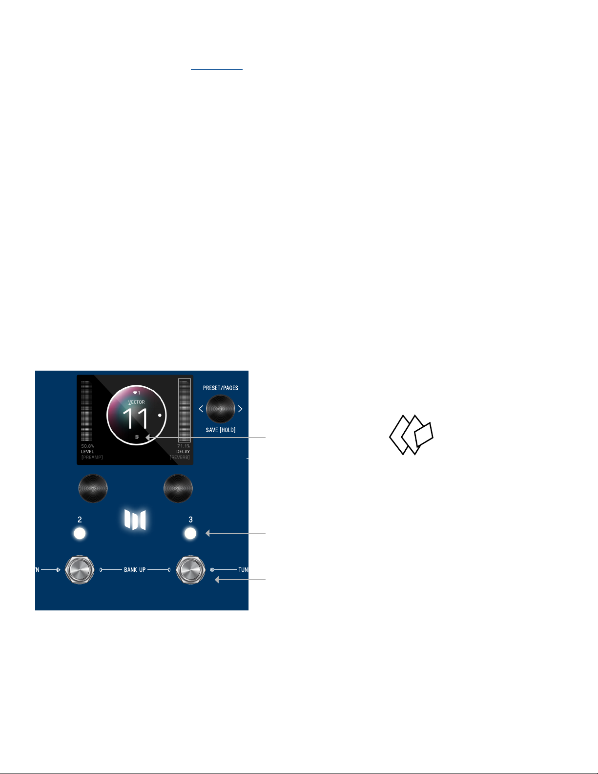
Any time edits are made, the “edited”
icon appears below the preset bubble.
For QUICK SAVE, hold the active/live LED button
Or hold active foot switch (below lit LED)
Hold down C3 knob again to save. Or QUICK SAVE.
To CANCEL a save, press any of the four footswitches. This will exit the SAVE AS PAGE without writing over your preset.
Note: If you cancel, no edits are saved.
Anytime you assign a Preset to a different Preset Number + Press and Hold C3 to save, you will automatically duplicate the
Preset. If you have exited the Save As Page, Press and Hold down C3 knob to enter the Save As Page. Turn C3 to the right
to highlight the Preset Number. Change the preset number to the copy destination. (To CANCEL a copy, press any of the four
footswitches.) To proceed a copy, Press and Hold C3 to a save a copy in the new location.
To QUICK SAVE without changing the name or favorite status, hold the active/lit LED button or foot switch directly below.
The completed save will return you to the PRESET PAGE and you’ll notice the “edited” glyph will have been removed.
SAVE PRESET OR CANCEL
COPYING A PRESET
QUICK SAVE
8
05- FAVORITES BANK
We created what we call the FAVORITES bank. The purpose of the FAVORITES BANK is to have a shortcut access to your top 3
favorite presets without the need navigate thru banks. The FAVORITES bank is located before bank 1. To jump to the
FAVORITES bank, HOLD 1+ 2footswitches. While the Favorites Bank is highlighted in the screen, use the 3 footswitches to
choose which favorite preset to jump to. To bank up, PRESS 2+ 3at the same time. To bank down, PRESS 1+ 2at the same
time. A total of 3 presets can be assigned to your FAVORITE BANK within the SAVE AS page.
HOLD 1+ 2footswitches to jump to FAVORITES bank.
Any preset that is favorited, includes a heart in the
preset bubble.

9
06- MODIFIERS
MercuryX has MODIFIERS which allow automatic control of your knobs. For each Modifier, you can choose which parameter the
modifier is automatically controlling, how fast the changes are happening, and how large the changes are.
To get to the Modifiers Edit Page, press C3 to enter the Edit Pages and turn C3 to MODIFIERS (named in middle bubble).
The Modifiers of MercuryX are identical to the ones in LVX except for the HOLD MODIFIER.
COMMON MODIFIER PARAMETERS
Speed: This sets how fast the Modifier completes a full cycle. LFO A, LFO B, S&H (a periodic random number generator) and the
Sequencer all feature a speed parameter that can be set independently. The Envelope Modifier doesn’t have a speed, but instead
features Attack and Decay Time which together set how long it takes the envelope to complete its cycle.
Note Division: Links the speed of the Modifier to MercuryX’s current delay Time. When Note Division is set, the Modifier’s Speed
parameter is ignored and the speed is calculated as a note division of the predelay time.
Assign: Each modifier is a self contained module that can automatically adjust a parameter in the MercuryX. To link a modifier to
a parameter, use the modifier’s ASSIGN parameter. Here you’ll find a list of all the available parameters you can link to the
modifier including NONE for when you don’t want to use the Modifier.
Min & Max: To set how much the Modifier changes the parameter use the Modifer’s Min and Mix controls. For the Min and Max
controls, the percentage relates to the current position of the parameter you are assigned to, where 100% equates to exactly
where the current parameter is set at. Having the Min and Max work as a percentage of the current parameter value allows you
to still control a parameter even when it is attached to a modifier. This is really useful if you like the way the modifier is working
but want to make general changes on the fly by simply adjusting the parameter directly.
MODIFIER EXAMPLE - CONTROLLING A FILTER
Let’s assign the LFO A Modifier to automatically change a filter’s frequency. First, turn C3 to a “BLANK” preset. Next, press C3
to enter the Edit Pages. Turn C3 to FILTER Category and change the Type to Ladder. While you are here, change the Location to
PRE+DRY, this will put the filter on to the dry path, in front of the delay. Finally let’s open up the Filter’s Frequency all the way to
15000 Hz. Resonance, Topology, and Spread can be left as is.
Now use C3 to navigate to the MODIFIERS Edit Page. Here we’ll use the first modifier, LFO A, to automatically change the filter.
Let’s change the LFO A Speed to 2 Hz and the LFO A Assign to FLTR-FREQUENCY. For now, let’s leave the other LFO A
parameters alone.
Let’s strum a few chords and listen to the result. You should hear the filter moving at its own rate and feeding the delay lines.
Since the delays and the filters are set to different speeds you can hear how they play against each other rhythmically. To syn-
chronize the filter frequency sweep with the delay time, Let’s change LFO A’s Note Division to QUARTER. Strum again, and you’ll
hear that the frequency sweep coincides with the predelay Time.

10
To fine tune the range of the sweep, let’s change the Min and Max parameters of LFO A. For Min and Max, the percentage relates
to the current parameter value, where 100% equates exactly to the current position. Since we have the Filter’s Frequency is
set to the maximum value of 15000 Hz, 100% exactly corresponds to this value and 0% corresponds exactly to the minimum
frequency value of 20Hz. Let’s set the LFO A Max to 68% for a gentler high frequency and the LFO A Min to 18% for a less
dramatic low frequency.
Finally let’s explore the different LFO A Shapes available. This control changes the waveshape which determines how the LFO
travels from begin to end in its cycle, ranging from the most gentle, Sine Wave, to the most abrupt, Square Wave. Experiment
with the different shapes to see how they affect your preset. As an experiment, try setting the LFO A Shape to Ramp Down,
the LFO A Note Division to 16th note, and LFO A MIN to 0% for filter with a rhythmic chopping response.
BREAKDOWN OF EACH MODIFIER AND ITS PARAMETERS:
LFO A Modifier - a periodic oscillating signal generator with selectable waveshapes
Parameters: Speed, Note Division, Shape (Ramp Up, Ramp Down, Triangle, Sine, Square, 3 Steps Up, 3 Steps Down, 4 Steps Up, 4
Steps Down), Assign, Minimum, Maximum
LFO B Modifier - a periodic oscillating signal generator with selectable waveshapes
Parameters: Speed, Note Division, Shape (Ramp Up, Ramp Down, Triangle, Sine, Square, 3 Steps Up, 3 Steps Down, 4 Steps Up, 4
Steps Down), Assign, Minimum, Maximum
Envelope Modifier - a note triggered envelope generator. When a note onset or pick attack is detected the envelope begins its
travel from the Min to Max value at the Attack Time before then traveling from Max back to Min at the Decay Time. The Linear
Shape completes this travel in a straight line and the Exponential Shape completes this travel using curved lines. The Clipped
Attack shape holds the envelope value at Max for the Attack Time interval before traveling back to the Min Value at the Decay Time
interval. Tip: try swapping the Min and Max values to flip the envelope shape.
Parameters: Attack Time, Decay Time, Shape (Linear, Exponential, Clipped Attack), Assign, Minimum, Maximum
Sample & Hold Modifier - a periodic random number generator, a new random number is generated after every cycle (set by Speed
or Note Division) is complete. Use this to randomly change a parameter at a fixed interval.
Parameters: Speed, Note Division, Assign, Minimum, Maximum
Sequencer Modifier - plays back a repeating pattern with a new element generated after every cycle (set by Speed or
Note Division) is complete. The pattern is created by setting 16 individual steps of equal length. Patterns less than 16 steps can
be created turning the step all the way down to its minimum value which is ‘Skip’.
Parameters: Speed, Note Division, Assign, Step 1 - 16
Some Modifiers Tips: MercuryX will allow you to assign multiple modifiers to the same parameter for creative control combinations.
When the modifiers are assigned to the same parameter the control signals they generate are added together before modifying the
parameter. This sum is automatically clipped at 100% when it gets too large.
When looking at the Assign parameter for any of the modifiers, MercuryX will only show the parameters for Categories where a
processing element has been selected. If the Type is set to None, then that Category will not appear in the list of Assign parameters.

11
Hold Modifier - a footswitch triggered envelope generator. The Hold Modifier’s envelope can be triggered by front panel footswitch,
LED switch, or MIDI command. The Hold Modifier can be set to Momentary, Latching or Tap Tempo action per preset. The LED
switch will light up to indicate when the modifier is active.
When set to Momentary, the envelope travels from the Min to Max value at the attack time while the footswitch is held.
When the footswitch is released, the envelope begins to travel back down to the Hold Min at the Decay Time.
When set to Latching, the envelope travels from the Min to Max value at the attack time while the footswitch is pressed.
The envelope will stay at the Max value until the next press where it will travel back down to the Min value at the Decay Rate.
The Latching mode is perfect for use as an on/off switch when assigned to the Mix parameter of a Category Type.
When set to Tap, the Hold Modifier switch functions as a traditional Tap Tempo switch that controls the predelay time.
Press either HOLD MODIFIER switch (per preset) to
explore it’s expressive function.

12
07- EXPRESSION
The rear panel of MercuryX has an EXP jack which allows you to connect an expression pedal for on the fly changes of
parameters. MercuryX lets you make 6 expression pedal assignments and for each assignment you can choose which
parameter the expression pedal is controlling, and how much the parameter is changed at the minimum and maximum positions of
the expression pedal. To get to the Expression Edit Page, press C3 to enter the Edit Pages and turn C3 to EXP PEDAL (named in
middle bubble).
Expression pedal adjustments affect the parameters only when an expression pedal is connected to the EXP jack on the back of
MercuryX. When a physical expression pedal is not connected to MercuryX, all EXP PEDAL assignments with the Source parameter
set to EXP will be ignored.
BREAK DOWN OF THE EXPRESSION PEDAL PARAMETERS:
Source A-F: Source sets which signal is used to modify the assigned parameter. By default, Source is connected to EXP
(the expression pedal). For most presets, having Source set to EXP is exactly what you want; where simply, the expression pedal
modifies the assigned parameter. Setting the Source to something other than EXP is useful when you want a modifier to control
a second parameter, see the example labeled ‘Using Expression Source’ below.
Assign A-F: MercuryX features 6 separate parameter assignments. To link the expression pedal to a parameter, use one of the six
expression pedal ASSIGN parameters labeled A through F. Here you’ll find a list of all the available parameters you can link to the
expression pedal including NONE.
Min & Max A-F: For each of the expression pedal parameter assignments you’ll find a corresponding set of Min and Max controls
also labeled A through F. Min represents the expression pedal at its minimum position (heel down), and Max represents the
expression pedal at its maximum position (toe down). The percentage relates to the current position of the parameter you are
assigned to, where 100% equates to exactly where the current parameter is set at. Having the Min and Max work as a percentage
of the current parameter value allows you to still control a parameter even when it is attached to an expression pedal. This is
really useful if you like the way the expression pedal is working but want to make general changes on the fly by simply adjusting
the parameter directly.
Expression Pedal Example - Controlling Pitch
Let’s assign the expression pedal to change the pitch of the Poly Chroma processing element.
First, connect your expression pedal to the EXP jack on the back of MercuryX.
Turn C3 to a BLANK preset. Press C3 to enter the Edit Pages. Turn C3 to PITCH Category and change the Type to Poly Chroma.
While you are here, change the Location to PRE+DRY, this will put the Poly Chroma on to the dry path, in front of the delay.
Also change the Poly Chroma’s Pitch parameter to 12 m2, and the Poly Chroma’s Mix parameter to 100%.
Turn C3 to the EXP PEDAL Edit Page. Change the first expression pedal assignment, EXP A Assign, Pitch-Pitch. This is shorthand
for the parameter where the first word stands for the Category (here we are targeting the Pitch Category) and the second word
stands for the actual parameter name (the Poly Chroma’s Pitch). Now, let’s change the EXP A Min to 50% and EXP A Max to

13
100%. Since we currently have the pitch parameter set to 12 m2 (an octave up, and the highest value for this parameter) 100%
will equate exactly to 12 m2, and 50% will equate exactly to the middle of the knob range 0 m2, which is zero pitch shift. Since
the Min parameter presents heel down and the Max parameter represents toe down on the expression pedal, moving the expression
pedal will smoothly move between no pitch shifting and an octave up of pitch shifting. Let’s strum a few chords while moving
the expression pedal and listen to the result.
Expression Pedal Example - Using Expression Source
Let’s create a preset to see how to use the Expression Source parameter to compliment the Modifier section in MercuryX.
Turn C3 to a BLANK preset. Before entering the Edit Pages, turn the front panel Mix knob to zero, doing this will let us listen to
anything in the Pre+Dry category with no echoes present.
Press C3 to enter the Edit Pages. Turn C3 to PITCH Category and change the Type to Lo-Fi. Change the
Location to PRE+DRY, this will put the Lo-Fi pitch on to the dry path, in front of the delay. Also change the Lo-Fi’s Pitch L and
Pitch R parameters to 12 m2, and the Lo-Fi’s Mix parameter to 100%.
Let’s assign an LFO modifier to Pitch L. Turn C3 to the MODIFIERS Edit Page. We’ll use the first modifier LFO A. Change LFO A
Assign to PTCH-PITCH L. For now, let’s leave the other LFO A parameters alone. If you take a listen, you’ll hear the left side of
the pitch changing from -12 to +12 semitones, and the right side will be statically shifted up 12 semitones.
To link Pitch R to the same modifier as Pitch L, we’ll use the Expression Source parameter. Turn C3 to the first EXP PEDAL Edit
Page. Set EXP SOURCE A to LFO A and EXP ASSIGN A to PTCH-PITCH R. Let’s leave the other EXP A parameters alone. If
you take another listen, you’ll now hear the pitch on the left and right channels moving together at the same rate since they are
both connected to the same modifier. While you are here, try changing EXP A MIN to 100% and EXP A MAX to 0%. Now, if you
take a listen you’ll hear the Pitch L and Pitch R parameters move opposite to each other but at the same rate since they are both
linked to LFO A.

14
08- PREDELAY
Traditionally, predelay is used to add a fixed amount of time between the start of your sound and when the reverb tank starts.
In the studio (currently), it typically is under 50 milliseconds. Adding predelay is a useful way to de-clutter and add clarity to your
sound by allowing your notes to breathe before they are enveloped by the sound of the reverb.
In MercuryX, we expand the concept and use of predelay by replacing a simple short mono delay line with twin 2.54 second delay
lines with modulation, selectable types, modulation, filtering, cross-feedback and a special routing position which allows you to
put any of the processing elements in the predelay’s feedback loop. A unique feature of the MercuryX’s predelay is the Dry Blend
control, that allows you to feed some signal from before the predelay into the tank.
COMMON DELAY PARAMETERS:
Time - The current delay time. This parameter is linked to the front panel Time knob, has 32 bit resolution, and can be expressed in
seconds or BPM by changing the “TEMPO DISP” setting in the Global Edit Pages. The Time parameter can be applied per preset or
globally to all presets by changing the “TEMPO SEL” parameter in the Global Edit Pages.
Left Division - This parameter sets the current time subdivision for the Left delay line and is expressed in note values. The division
parameter is useful when you want to automatically adjust your Left delay to a specific note value ratio of the Time parameter.
In the “BLANK” preset, this parameter defaults to “OFF”, which gives you quarter note divisions that match the blinking Tap LED on
the front panel.
Right Note Division - This parameter sets the current time subdivision for the Right delay line and is expressed in note values. The
division parameter is useful when you want to automatically adjust your Right delay to a specific note value ratio of the Time pa-
rameter. In the “BLANK” preset, this parameter defaults to “OFF”, which gives you quarter note divisions that match the blinking
Tap LED on the front panel.
Half Speed - This sets the current read/write speed for the delay line. When half speed is disabled the delays operate at 48 kHz
sampling rate giving you a maximum delay time of 2.54 seconds of stereo delay time; and when half speed is enabled the delays
operate at 24 KHz giving you 5.08 seconds of delay time. Try changing the Half Speed parameter while the delays are echoing
with a generous amount of feedback to create interesting time and pitch effects.
Feedback - This controls the amount of the delay line’s output that is mixed onto the delay line’s input. This parameter is linked to
the front panel Feedback knob and sets the feedback for both the Left and Right delays.
Crossfeed - This control works with the feedback parameter to set how much of the Left delay output is mixed onto the Right
delay input, and how much of the Right delay output is mixed onto the Left delay input. Use this to create interesting cascading
delay effects when the Left and Right delays have different settings.
Mod - This parameter sets the amount of modulation to the Left and Right delay lines, and has a different voicing for each Delay
Type. This parameter is linked to the front panel Mod knob, and is not connected to the Modulation category. The Mod parame-
ter is useful to quickly dial in some motion to animate your delay lines. For deeper and more complete modulation control, use the
Modulation category when you want to enhance your delay lines with even more modulation.

15
Damping - This parameter reduces the high frequencies in the Left and Right delays. When set to zero, the delays have the full
amount of high frequency detail. The Dampening parameter has a different response per Delay Type. For the Digital delay type, the
Damping control allows you to darken your repeats. For the BBD delay type, the Damping control alters the filter structure around
the bucket brigade clock, with no clock noise preset when color is set to 100%. For the Tape delay type, the Damping control
changes the filter structure and ages the tape to allow for darker timbres.
Dry Blend
This parameter controls the amount of dry signal added to the output of the predelay. Dry Blend defaults to 0%, which recreates
how a typical predealy works. Dry Blend works especially well with long predelay times and lets some of your dry signal hit the
reverb tank before the initial predelay reflection.
Here is a deep dive into the 8 different reverb structures in MercuryX. Each Reverb Structure has Gate controls that can be used
to dial in a range of gated reverb effects including the classic percussive gate sound, reverse tail reverb sounds, and slow breathing
textures. Similar to the Dry Blend control of the Predelay, each Reverb Structure features a Predelay Blend control that allows you
to put some or all of the predelay reflections in parallel with the reverb tank.
Ultraplate - Adapted from Mercury7, Ultraplate is an inspiring and lush plate with a fast build. Use the Ultraplate’s flexible decay
range to create a wide range of studio textures.
Parameters: Decay, Lo Freq, Hi Freq, Mod Speed, Mod Depth, Pitch, Pitch Mix, Diffusion, Predelay Blend, Gate Attack, Gate Hold,
Gate Decay
Cathedra - Adapted from Mercury7, Cathedra is a massive and ethereal algorithm with a slow build. Cathedra is perfect for sci-fi
textures and recreating C-beams glittering in the dark near the Tannhauser gate.
Parameters: Decay, Lo Freq, Hi Freq, Mod Speed, Mod Depth, Pitch, Pitch Mix, Diffusion, Predelay Blend, Gate Attack, Gate Hold,
Gate Decay
Spring - A flexible algorithm that can be voiced to replicate both the amp based reverb sounds and the classic studio spring tanks
featured on early recordings.
Parameters: Dwell, Lo Freq, Hi Freq, Predelay Blend, Gate Attack, Gate Hold, Gate Decay
78 Room - A lively and direct sound. This algorithm is great for transforming static sounding virtual amps into the difficult to
capture sound of a great amp live in the room with you. The Room algorithm features a unique infinite mode (Maxed out Decay
controls) that interacts with the Tank Mod to provide deep chorused and flanged reflections.
Parameters: Mids, Bass, Treble, Cross, Tank Mod, Diffusion, Predelay Blend, Gate Attack, Gate Hold, Gate Decay
78 Plate - Fast and dense, the 78 Plate algorithm is a good match for beefing up percussion and vocals.
Parameters: Mids, Bass, Treble, Cross, Tank Mod, Diffusion, Predelay Blend, Gate Attack, Gate Hold, Gate Decay
- REVERB STRUCTURES
09

16
78 Hall - A large hall with a medium build up of reflections. Great for building up ambient walls of sound. The Hall algorithm’s
extended reflections are a great base for sculpting with the Bass/Mids/Cross controls. Deep rumbling bass caverns and ethereal
upper mid emphasized halos of sound are easy to create. Explore the additional sparse mode for the Hall when Diffusion is set
Low.
Parameters: Mids, Bass, Treble, Cross, Tank Mod, Diffusion, Predelay Blend, Gate Attack, Gate Hold, Gate Decay
Prism - The Prism Structure is an dual tank that allows you to build your own geometric rooms by specifying the size and
distance and reflectivity. Prism features a highly configurable modulation section which allows different modulation phases per side
to further increase the stereo image.
Parameters: Decay, Size, Dispersion, Distance, Lo Cut, Hi Cut, Mod Speed, Mod Depth, Mod Phase, Predelay Blend, Gate Attack,
Gate Hold, Gate Decay
Gravity - The Gravity Structure works by accelerating individual windows of your signal and stretching them across the horizon.
Gravity is great for adding padlike textures beneath to your sound and features an powerful modulation section capable of both
gentle and chaotic pitch effects inside of the reverb tank. Gravity’s Gain control is crucial to taming the explosive textures con-
tained within.
Parameters: Decay, Tilt EQ, Mod Speed, Mod Depth, Mod Feedback, Gain, Mod, Predelay Blend, Gate Attack, Gate Hold, Gate Decay
10- CATEGORIES AND ELEMENTS
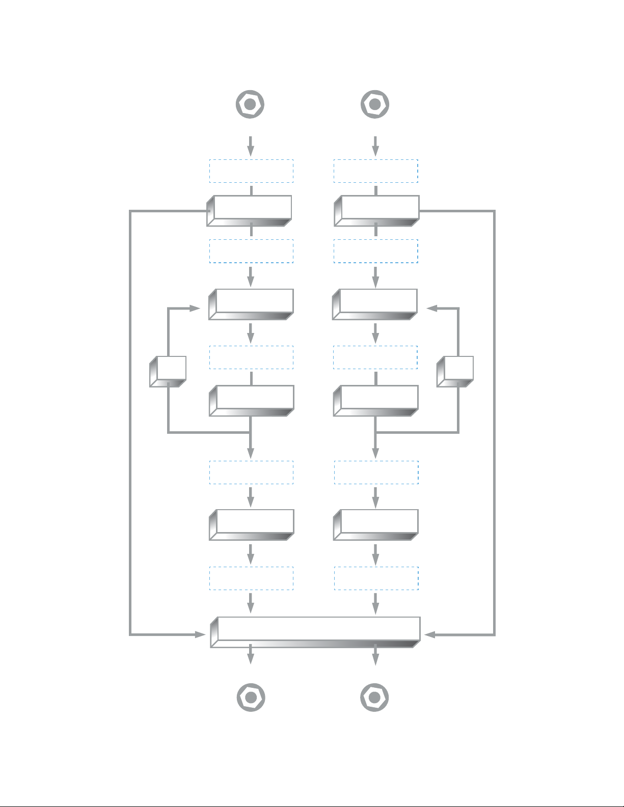
The processing elements are grouped into categories. The categories are: Dynamics, Preamp, Filter, Pitch, and Modulation.
Important: the Modulation Category is separate from the front panel Mod knob which directly controls the modulations built into the
predelay. In MercuryX, the elements can be placed before the delay lines, after the delay lines, in the feedback of the delay lines,
as well as in the pre + dry path indicated in light blue. When all categories are in the same location, the processing order from
first to last is Dynamics, Preamp, Filter, Pitch, and Modulation.
17
Visual diagram of the processing elements:
R
I
G
H
T
I
N
P
U
T
L
E
F
T
I
N
P
U
T
MIX
MIX
FEEDBACK MIXER
FEEDBACKFEEDBACK
PREDELAY PREDELAY
REVERB REVERB
FEEDBACK MIXER
MIX
PRE + DRY LOCATIONPRE + DRY LOCATION
PRE LOCATIONPRE LOCATION
PRE TANK LOCATION PRE TANK LOCATION
POST LOCATION POST LOCATION
FEEDBACK LOCATION FEEDBACK LOCATION
R
I
G
H
T
O
U
T
P
U
T
L
E
F
T
O
U
T
P
U
T
This manual suits for next models
1
Table of contents
Other Meris Recording Equipment manuals


