Pro-face GP3000 Series User manual

1
GP3000 Series
CANopen Interface
Installation Guide
Package Contents
(1) Installation Guide (1) <This Guide>
This unit has been carefully packed, with
special attention to quality. However, should
you find anything damaged or missing, please
contact your local GP distributor immediately.
About the Manual
For the detailed information on GP3000
series, refer to the following manual.
• GP3000 Series Hardware Manual
• Maintenance/Troubleshooting Guide
The manuals can be selected from the help
menu of GP-Pro EX or downloaded from
Pro-face Home Page.
URL
http://www.pro-face.com/
Caution
Be sure to read the “Warning/Caution
Information” on the attached sheet before
using the product.
CAUTION
This manual describes the part names and
general specifications related to the
CANopen I/F included with the CANopen
board type unit of the GP3000 series, as
well as the wiring to the CANopen
connector. Before using the CANopen
connector, be sure to read this Installation
Guide in conjunction with the attached
GP3000 Series’ Installation Guide.
2
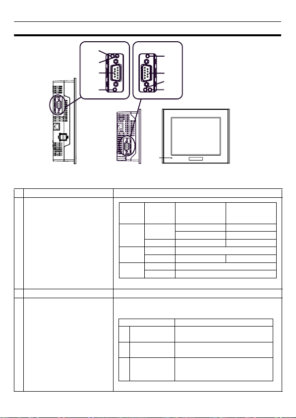
Part Names and Functions
Name Description
AStatusLED
BCANopen Interface Dsub 9-pin connector (plug.)
C
D
ECANopen Status LED
This LED indicates the communication status of the
CANopen.
Left side
(AGP-3500T)
AFront
B
C
(AGP-3300T)
D
E
D
B
The arrangement of CANopen I/F and its peripheral equipment differs between the GP-3300/GP-3400 Series
and the GP-3500/GP-3600 Series.
EC
Color Indicator Operation Mode
(Drawing) Logicexecution
mode (when
logic is enabled)
Green ON OFFLINE -
In operation RUN
Flashing In operation STOP
Red ON When power is turned on.
Flashing In operation Major Error
Orange ON Backlight burnout
Flashing During software startup
Status LED Indicates
C PWR (Green) ON: When applying current,
OFF: When light is off
D RUN (Green) Turns on when Communication
is enabled.
E ERR (Red) Turns on when failure occurs in
connected slaves (ex.) Hybrid
Terminal Block.
3
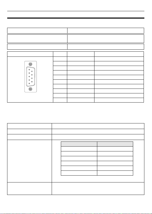
CANopen Specifications
CANopen Interface
CANopen Data Transfer Settings
CANopen is the networking concept based on the international standard CAN. CANopen is
defined as a uniform application layer by the DS 301 specifications of the CiA (CAN in
automation).
Connector (GP unit side) XM2C-0942-502L <OMRON Co.>
Recommended Cable connector
(Cable side) See page 5.
Interfit Bracket #4-40 (inch screws are used.)
Pin Arrangement Signal Name Description
1
-
2 CAN_L CAN-L bus line
3 CAN_GND CAN ground
4
-
5
-
6
-
7 CAN_H CAN-H bus line
8
-
9
-
Shell FG Frame Ground (Common with SG)
Communication Type 1:N
Connection Method Multi Drop Connection
Transfer Method CSMA/NBA. Half-duplex serial transmission.
Transfer distance speed/
Transmission length
No. of nodes 63 nodes max. Bit variable input: 512 points*1, Bit variable
output: 512 points*1, Integer variable input: 128 points*2,
Integer variable output: 128 points*2.
*1 When using GP-Pro EX under Ver.2.50, Bit variable enables to input/output 256 points.
*2 When using GP-Pro EX under Ver.2.50, Integer variable enables to input/output 64 points.
6
(GP Unit Side)
9
5
1
Baud rate*1 Bus length
1000 kbps 20m
800 kbps 40m
500 kbps 100m
250 kbps (factory settings) 250m
125 kbps 500m
50 kbps 1000m
*1 Set the baud rate with the software.
4
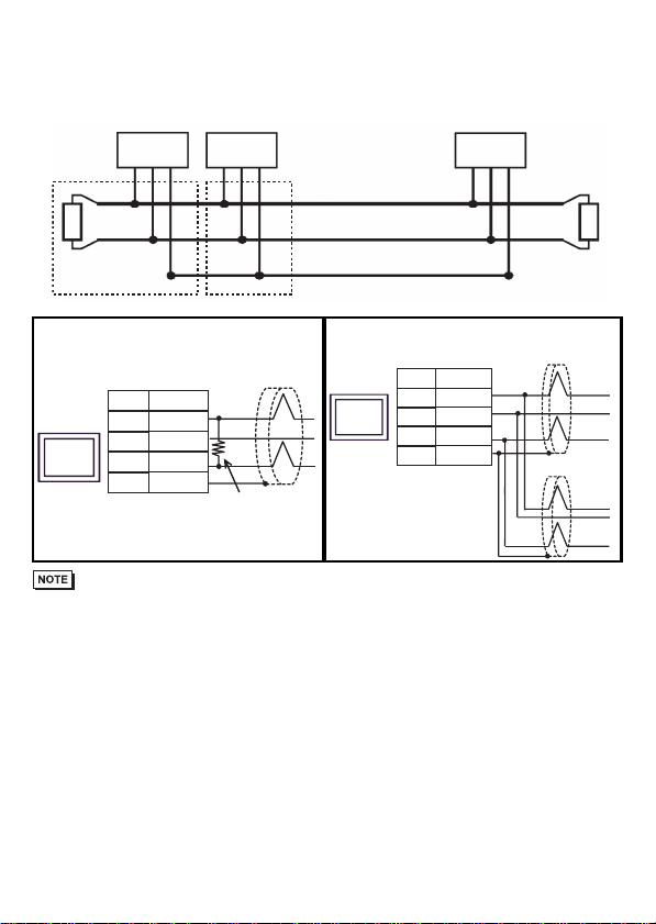
CANopen cable arrangement
The CANopen interface uses DSUB 9-pin plug connector. The plug is assigned with the
CAN_H, CAN_L and CAN_GND connections. CAN_H and CAN_L are two physically
different bus levels. CAN_GND is the common reference potential.
• The cable’s resistance value should be 70mΩ./m or less.
• The above diagrams shows the case used the cable connector “XM2D-0901“ by OMRON Co.
Line termination
To minimize the signal’s reflections from the end of the cable, a line termination shall be placed
close to the 2 ends of the bus. Connect both ends of the twisted pair cable(CAN_H and CAN_L)
to each LT. Use line termination whose resistance value is 120 Ω. (Resistance Tolerance: 5%
maximum, Rated Power: 1/4 W minimum)
LT = Line Termination
Node 1 Node 2 Node n
LT
CAN_H
CAN_L
CAN_GND
Twisted Pair Cable LT
Diagram 1 Diagram 2
GP
Termination
Resistance
ShieldD-sub 9 pin (socket)
CAN-L
Signal
name
2
CAN-H
CAN-GND
FGShell
3
7
Pin
GP
D-sub 9 pin (socket)
CAN-L
Signal
name
2
CAN-H
CAN-GND
FGShell
3
7
Pin
Shield
Shield
Diagram 1 Diagram 2
5
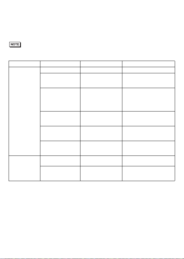
CANopen communication cable and other recommended items
Recommended Cable Connector:
CiA-recommended CANopen (CiA DR-303-
1) -compatible DSUB 9-pin connector
(DIN41652) .
CANopen Recommended Transfer Cable:
CiA-recommended CANopen (CiA DR-303-
1) -compatible twisted pair cables with
shield.
• Please use your own cables or cable connectors with your guarantee.
Model No. Manufacturer Description
Recommended
Cable Connector XM2D-0901 <OMRON Co.> DSUB 9-pin socket
TSXCANKCDF180T <Schneider Electric> Straight connector with
terminal selector switch
attached
TSXCANKCDF90T
TSXCANKCDF90TP <Schneider Electric>
Right-angled connector with
terminal selector switch
attached.
Only for use for GP-3300
Series.
VS-09-BU-DSUB/CAN <PHOENIX CONTACT> Connector with terminal block
attached with terminal selector
switch attached
SUBCON-PLUS-CAN/AX
<PHOENIX CONTACT> Straight connector with
terminal selector switch
attached
SUBCON-PLUS-CAN/PG
SUBCON-PLUS-CAN
<PHOENIX CONTACT> Right-angled connector with
terminal selector switch
attached
CANopen
Recommended
Transfer Cable
TSX CAN CA50/TSX
CAN CA100 <Schneider Electric> Cable for CANopen
(IEC60332-1) 50 m/100 m
TSX CAN CB50/TSX
CAN CB100 <Schneider Electric> UL-authenticated cable for
CANopen
(IEC60332-2) 50 m/100 m
Other manuals for GP3000 Series
6
This manual suits for next models
13
Table of contents
Other Pro-face Recording Equipment manuals

Pro-face
Pro-face GP3000 Series User manual

Pro-face
Pro-face ST3200 Series User manual

Pro-face
Pro-face GP-4114T User manual

Pro-face
Pro-face GP2000H Series User manual

Pro-face
Pro-face GP-2401T User manual

Pro-face
Pro-face LT-4201TM User manual

Pro-face
Pro-face ST3200 Series User manual

Pro-face
Pro-face GP-4100 series User manual

Pro-face
Pro-face GP-4100 series User manual

Pro-face
Pro-face ST3000 Series User manual


