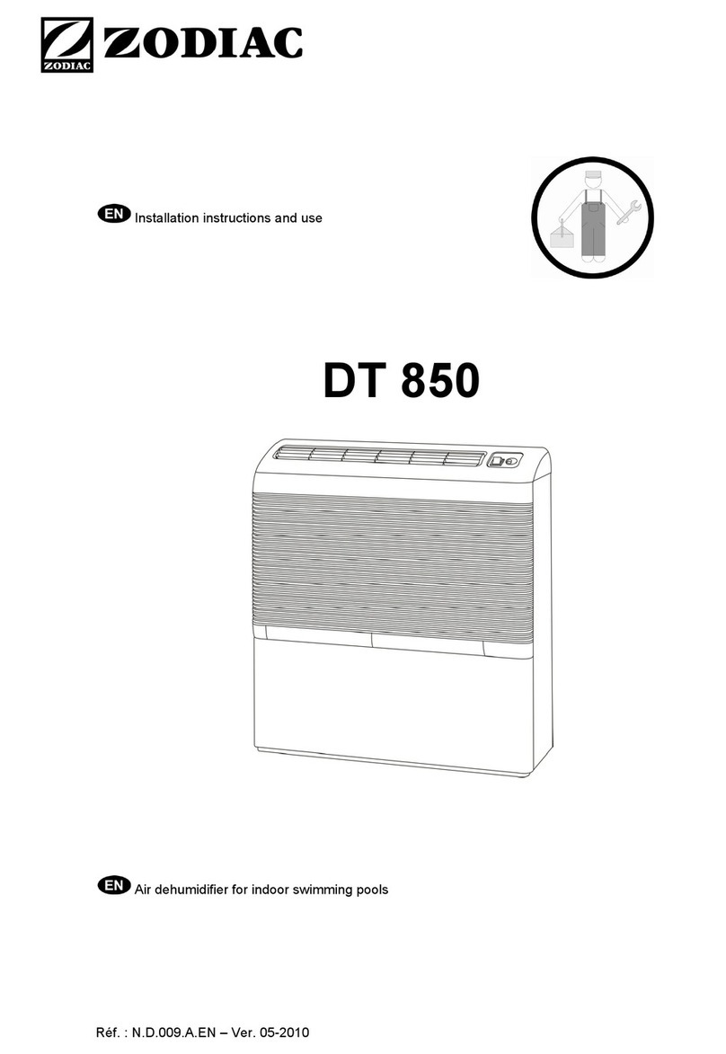
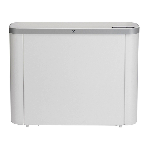
Zodiac DT850E User manual

H0369900_REVC - 2021/01
More documents on:
www.zodiac.com
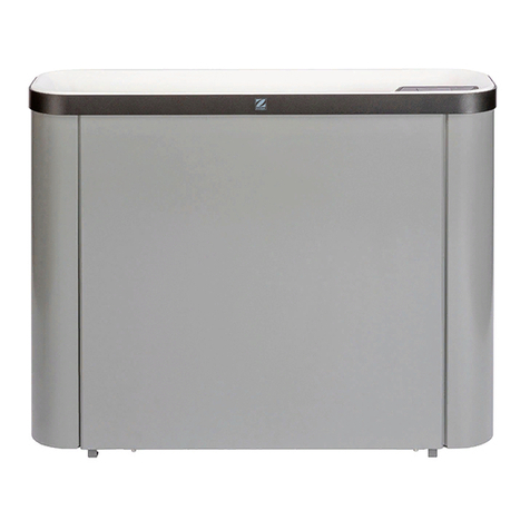
DT 850 E
EN
Instructions for installation and use - English
Dehumidifier
Translation of the original instructions in French

1
WARNINGS
Carefully read the instrucons in this manual before using the unit.
• Before handling the appliance, it is vital that you read this installaon and user
manual, as well as the "Warranes" booklet delivered with the appliance. Failure
to do so may result in material damage or serious or fatal injury and will void the
warranty.
• Keep and pass on these documents for reference during the appliance's service life.
• The distribuon or modicaon of this document in any way is prohibited, without
prior authorisaon from the manufacturer.
• The manufacturer is constantly developing its products to improve their quality.
The informaon contained herein may therefore be modied without noce.
GENERAL WARNINGS
• Failure to respect the warnings may cause serious damage to the pool equipment
or cause serious injury, even death.
• Only a person qualied in the technical elds concerned (electricity, hydraulics or
refrigeraon) is authorised to carry out maintenance or repair work on
the appliance. The qualied technician working on the appliance must
use/wear personal protecve equipment (such as safety goggles and
protecve gloves, etc.) in order to reduce the risk of injury occurring
when working on the appliance.
• Before handling the appliance, check that it is switched o and isolated.
• The appliance is intended to be used for pools and spas for a specic purpose; it
must not be used for any purpose other than that for which it was designed.
• This appliance is not intended for use by individuals (including children) with
impaired physical, sensorial or mental abilies, or persons lacking in knowledge
and experience, unless they receive supervision or prior instrucons on using the
appliance from a person responsible for their safety. Children must be supervised
to ensure that they do not play with the appliance.
• This appliance can be used by children over 8 and adults with impaired physical,
sensory or mental capabilies, or who lack experience and knowledge, if they are
correctly supervised or have been instructed in how to use the appliance safely
and understand the hazards involved. This appliance should not be cleaned or
maintained by children without supervision.
• The appliance must be installed according to the manufacturer’s instrucons and
in compliance with local and naonal standards. The installer is responsible for
installing the appliance and for compliance with naonal installaon regulaons.
Under no circumstances may the manufacturer be held liable in the event of failure
to comply with applicable local installaon standards.
• For any work other than the simple user maintenance described in this manual, the
product should be referred to a qualied professional.
• If the appliance suers a malfuncon, do not try to repair it yourself; instead contact
a qualied technician.
• Deacvang, eliminang or by-passing any of the safety mechanisms integrated
into the appliance shall automacally void the warranty, in addion to the use of
spare parts manufactured by unauthorised third-party manufacturers.
• Do not spray inseccide or any other chemical (inammable or non-inammable)
in the direcon of the appliance, as this may damage the body and cause a re.
• Do not touch the fan or moving parts or insert objects or your ngers into the
appliances' grids or near moving parts when the appliance is in operaon. Moving
parts can cause serious injury or even death.
2
WARNINGS CONCERNING APPLIANCES CONTAINING REFRIGERANT
• R290 refrigerant is classed under category A3 as highly ammable.
• The appliance must be stored in a room without any permanent ignion source
(such as open ames, operang gas appliance or operang electric heang).
• Do not use means for accelerang the defrosng or cleaning process other than
those recommended by the manufacturer.
• No not perforate or incinerate.
• Please note that R290 refrigerant may give o a certain odour.
INSTALLATION AND MAINTENANCE
• The appliance may not be installed close to combusble materials, or the air duct
inlet of an adjacent building.
• With some appliances, it is essenal to t a "protecon grid"-type accessory if the
unit is installed in an area with uncontrolled access.
• During installaon, troubleshoong and maintenance, pipes may not be used as
steps: the pipe could break under the weight, spilling refrigerant and possibly
causing serious burns.
• When servicing the appliance, the composion and state of the heat transfer uid
must be checked, as well as the absence of any traces of refrigerant.
• During maintenance work, ensure there are no traces of corrosion or oil around
the cooling components.
WARNINGS ASSOCIATED WITH ELECTRICAL APPLIANCES
• The power supply to the appliance must be protected by a dedicated 30 mA Residual
Current Device (RCD), complying with the standards and regulaons in force in the
country in which it is installed.
• Do not use any extension lead when connecng the appliance; connect the
appliance directly to a suitable power supply.
• Before carrying out any operaons, check that:
- The required input voltage indicated on the appliance informaon plate
corresponds to the mains voltage;
- The mains supply is compable with the appliance's electricity needs and is
correctly grounded.
• In the event of abnormal operaon or the release of odours from the appliance,
turn it o immediately, unplug it from its power supply and contact a professional.
• Before servicing or performing maintenance on the appliance, check that it is
powered o and completely disconnected from the power supply. Moreover,
check that the heang priority (where applicable) is deacvated and that any
other device or accessory connected to the appliance is also disconnected from
the power supply.
• Do not disconnect and reconnect the appliance to the power supply when in
operaon.
• Do not pull on the power cord to disconnect it from the power supply.
• If the power cord is damaged, it must be only replaced by the manufacturer, an
authorised representave or a repair shop.
• Do not perform maintenance or servicing operaons on the appliance with wet
hands or if the appliance is wet.
• Before connecng the appliance to the power supply, check that the connecon
unit or socket to which the appliance will be connected is in good condion and
shows no signs of damage or rust.
• In stormy weather, disconnect the appliance from the power supply to prevent it
from suering lightning damage.
• Do not immerse the appliance in water or mud.
• Always unplug the device from the mains when it is not in use.
EN

3
• Before beginning work on the cooling circuit, stop the appliance and wait for a few
minutes before ng the temperature and pressure sensors. Some elements such
as the compressor and piping may reach temperatures in excess of 100°C and high
pressures with the consequent risk of severe burns.
TROUBLESHOOTING
• All brazing must be carried out by qualied brazers.
• Replacement pipes must always be made of copper in compliance with standard NF
EN 12735-1.
• Leak detecon; pressure test:
- never use oxygen or dry air, risk of re or explosion,
-use dry nitrogen or the mixture of nitrogen and refrigerant indicated on the
informaon plate,
- the test pressure for both the high and low pressure circuits must not exceed 42
bar in cases where the appliance is equipped with the oponal pressure gauge.
• The high pressure circuit pipes are made of copper and have a diameter equal to or
greater than 1’’5/8. A cercate as indicated in §2.1 in compliance with standard
NF EN 10204 must be requested from the supplier and led in the installaon's
technical le.
• Technical data relave to the safety requirements of the various applicable direcves
are indicated on the informaon plate. All this informaon must be recorded in the
appliance's installaon manual, which must be kept in its technical le: model, code,
serial number, maximum and minimum OT, OP, year of manufacture, CE marking,
manufacturer’s address, refrigerant and weight, electrical parameters, thermo-
dynamic and acousc performance.
LABELLING
• The equipment must be labelled so as to specify that it is out of order and that the
refrigerant has been drained.
• The label must be dated and signed.
• For appliances containing a ammable refrigerant, check that labels are placed on
the equipment stang that it contains a ammable refrigerant.
RECOVERY
• When draining the refrigerant for maintenance or decommissioning, best pracces
should be followed in order to safely drain all of the refrigerant.
• When transferring refrigerant to a cylinder, make sure that you use a recovery
cylinder that is compable with the refrigerant. Make sure that the correct number
of cylinders are provided for recovering all of the refrigerant. All cylinders used must
be intended for the recovery of refrigerant and must be labelled for this specic
refrigerant. The cylinders must be equipped with a vacuum valve and a stop gate
in good working order. Empty collecon cylinders are drained and, where possible,
cooled before recovery.
• The recovery equipment must be in good working order, the instrucons for using the
equipment must be within reach and the equipment must be compable for use with
the refrigerant concerned, including, where appropriate, a ammable refrigerant.
Moreover, a set of calibrated scales must be available and in good working order.
The pipework must be complete, have no leaks or disconnected connectors, and
must be in good condion. Before using the recovery unit, check that it is in good
working order, that it has been well maintained and that the associated electric
components are sealed so as to prevent any risk of re in the event of refrigerant

4
being released. If you have any doubts, contact the manufacturer.
• The recovered refrigerant must be sent to the refrigerant supplier in its recovery
cylinder with a waste transfer note. Do not mix dierent refrigerants in the recovery
units, and in parcular in the cylinders.
• If the compressor has been removed or if oil from the compressor has been drained,
check that the refrigerant has been completely removed to prevent it from mixing
with the lubricant. The draining process must be carried out before returning the
compressor to the supplier. Only the electric heater of the compressor body can
be used to accelerate this process. This operaon can be carried out safely once all
liquids within the system have been drained.
Recycling
This symbol is required by the European direcve DEEE 2012/19/EU (direcve on waste electrical and electronic
equipment) and means that your appliance must not be thrown into a normal bin. It will be selecvely collected
for the purpose of reuse, recycling or creang value. If it contains any substances that may be harmful to the
environment, these will be eliminated or neutralised. Contact your retailer for recycling informaon.
EN

5
CONTENTS
❶ Specicaons 6
1.1 I Descripon 6
1.2 I Dimensions and marking 6
1.3 I Technical specicaons 7
❷ Installaon
8
2.1 I Installing the appliance
8
2.3 I Electrical connecons 10
❸ Use 10
3.1 I Operang principle 10
3.2 I User interface presentaon 10
3.3 I Starng the appliance 11
❹ Maintenance 12
4.1 I Maintenance 12
❺ Troubleshoong 15
5.1 I Appliance behaviour 15
5.2 I Electrical diagram 15
Tip: to make it easier to contact the retailer
• Write down the retailer's contact details to help you nd them more easily and ll in the "product"
informaon on the back of the manual: the retailer will ask for this informaon.

6
❶ Specicaons
1.1 I Descripon
DT 850 E
An-vibraon studs (round)
An-vibraon studs (rectangular)
Screw
Plugs
Mounng bracket
: Included
1.2 I Dimensions and marking
750 mm
345 mm
660 mm
Sucon grid
Blower grid
User interface
EN

7
1.3 I Technical specicaons
DT 850 E
Voltage 220-240 V / 1N / 50 Hz
Nominal absorbed intensity* A4.30
Maximum current input (at start-up) A20
Minimum cable secon** mm² 75
3G0
Dehumidifying capacity* L/h 2.2
Nominal power input* W 970
Air ow (at maximum speed) m³/ h 500
Sound pressure at 1 m db(A) 20
Approximate weight kg 37
Cooling uid R290
Cooling uid load kg 0.3
Service pressure (min/max) bar 8.5/22
MPa 0.85/2.2
Operang range of pool room °C 7 - 35
Protecon rang IP24
* Following nominal condions: ambient air at + 30°C, relave humidity of 70%
** Values provided as a guide only for a maximum length of 20 metres, these must be veried and adjusted to suit the installaon
requirements and the installaon standards of the country.

8
❷ Installaon
2.1 I Installing the appliance
2.1.1 Selecng the locaon
•The appliance must be installed in accordance with the IEC/HD 60364-7-702 standard and the naonal
regulaons in force for swimming pools.
•Only indoor installaon is possible: ensure there is easy access to the appliance for maintenance and
connecons.
•Leave at least 60 cm between the top of the appliance and any other object.
•The appliance should only be installed in a room at least 15 m².
•Ensure the appliance is installed level on its four feet or on the mounng bracket to prevent any
overows from the condensaon tray,
•The appliance's feet must not be soaking in water,
•Place nothing in front of or on the blowing and sucon grids,
•Risk of stracaon:
-height of the room < 4 to 5 metres: mechanical venlator unit or extractor,
-height of the room > 5 to 8 meters: ceiling fans with large blades.
•Building requirements: pool room = high relave humidity,
•During building make sure that:
-the materials used are compable with a swimming pool environment,
-the walls are suciently waterproofed and insulated to prevent condensaon from forming in the
room when relave humidity reaches 60 to 70%,
• Buildings with lightweight structures (verandas, shelters, etc.): : there is no risk of deterioraon of the
structure, even in case of dew (they are designed to support this, even with a relave humidity of 70%),
•Venlaon, renewal of air:
-private pools: highly recommended,
-public pools: compulsory,
•The air can be renewed by:
-a simple mechanical venlaon unit,
-a wall or roof extractor with fresh air intake grids.
•This venlaon ensures the hygienic renewal of air, the removal of any chloramines or other corrosive
chemicals present in the air, and the eliminaon of excessively hot air, whilst contribung to the
dehumidicaon of the room.
: DT 850 E
: Condensates drain
with siphon
: Air renewal system
: Fresh air intake
* Minimum distance
(in compliance with the
applicable standards in the
country of installaon)
** Maximum distance
EN

9
2.1.2 Posioning the appliance
•The appliance can be installed on the oor or xed to the wall using the supplied mounng bracket .
•Make sure that the device is perfectly horizontal in both these cases.
• If the device is installed on the ground:
- Fix the 2 supplied round an-vibraon studs in the intended locaons at the boom corners of the appliance's
rear panel.
- Make sure that all 4 feet are touching the ground.
• If the device is mounted on the wall:
•Only use xing parts that are suitable for the supported weight (approximately 40 kgs)
- Secure the mounng bracket to a solid wall using at least 5 screws and plugs (provided).
- Sck the 2 supplied rectangular an-vibraon studs (self-adhesive) between the mounng bracket and the
appliance to avoid vibraons spreading through the wall.
- Fix the 2 supplied round an-vibraon studs in the intended locaons at the boom corners of the appliance's
rear panel.
- Fasten the appliance on the bracket.
- Make sure that all the an-vibraon studs are correctly placed.
2.1.3 Connecng the condensate drainage line
Make sure that the pipe cannot freeze in condions of extreme cold and frost.
•Join a suitable diameter drain pipe to the original pipe (external diameter Ø16),
•The angle should be sucient to ensure a correct ow by gravity.
•Place the end of the pipe in a drainage ng equipped with a siphon,
•Make sure the pipe is not twisted or bent, and that the end of the pipe is not submerged.
The condensates outlet can be modied by angling it towards the le or right rear of the appliance. To do this, remove
the rear panel and run the drainage line to one of the chosen openings (see ref. ).

10
2.3 I Electrical connecons
•The appliance is only suitable for a grounded socket (2P + E wall socket), 220-240 Volt (50 Hz) connecon
voltage. If the power supply is not earthed, do not plug in your appliance unl the appropriate earthing
has been installed by a qualied professional.
•The appliance must be installed and protected by a residual current device (RCD) with a maximum current
of 30 mA.
•All extension cables or mulsocket connects are prohibited. Request the installaon of a protected power
socket near the appliance from a qualied technician.
•The installer must consult the electricity provider if necessary and ensure that the equipment is connected
correctly to an electricity network with impedance under 0.095 ohm.
•The power supply must correspond to the voltage indicated on the appliance's informaon plate.
•The power cord must be insulated against any cung or hot elements that may damage or crush it.
❸ Use
3.1 I Operang principle
This dehumidier operates based on a heat pump with extracon of the warm, humid air in the pool room and delivery
of dryer, hoer air.
It is ideal for maintaining a humidity level that is between 60 % and 70 %.
When the humidity level is lower than 60 %, this leads to a feeling of excessive cold when leaving the water.
When it is higher than 70 %, this leads to too much moisture and condensaon in the room.
3.2 I User interface presentaon
Display
Ambient humidity level
Buons
On/O
Humidity level adjustment
Fan speed adjustment
Indicator lights
Compressor operaon
Connuous operang mode
Fan speed ("HI": fast, "LO": slow)
Humidity level
EN

11
3.3 I Starng the appliance
•The appliance must have lters ed when operang.
•Avoid opening doors and windows when using the appliance.
•Power on the device by plugging in the power cable,
•Press the buon : the fan speed and desired humidity level indicators light up (last acve sengs),
•Set the desired humidity level using the "HUMIDITY" buon (40%, 50%, 60%, 70%) or set the appliance to connuous
operaon using "CNT",
•The connuous operang mode does not take humidity levels into account: the device operates
connuously.
•Adjust the speed of the fan with the "SPEED" buon.
•Check that the appliance is draining condensates when in operaon (see "2.1.3 Connecng the condensate drainage
line").
•Aer a 5 minute delay, if the level of ambient humidity is higher than the desired humidity level, the
compressor starts up and the "COMP." indicator lights up.
•A comfortable humidity rate for pool use is 60%.
•Venlaon is permanent while the appliance is switched on.
•The dehumidier is equipped with a defrosng system which starts automacally as soon as frost
forms during low temperatures. The compressor automacally starts-up or stops based on the ambient
temperature. The fan operates connuously.
•When the humidity level is less than 35% in connuous operaon mode, the appliance permanently
displays "LO" but the compressor and the fan connue to operate at the selected speed. Switch o the
appliance or select a humidity rate so that it rises to the ideal or desired rate.

12
❹ Maintenance
4.1 I Maintenance
•Before performing any maintenance operaon on the appliance, carefully read the safety
instrucons, see "4.1.1 Safety instrucons for appliances containing R290 refrigerant".
•Before any maintenance work on the appliance, you must cut the electricity supply as there is
a risk of electric shock which may cause material damage, serious injury or even death.
•It is recommended that the appliance undergo general servicing at least on a yearly basis to
ensure its proper operaon, maintain performance levels, prevent any possible failures, and
protect the building.
•These operaons are at the users' charge and must be performed by a qualied technician.
•Never clean the dehumidier by spraying it with water or immersing it in water (risk of short-
circuit).
4.1.1 Safety instrucons for appliances containing R290 refrigerant
Area check
•Before starng work on systems containing ammable refrigerants, safety checks must be carried out to guarantee a
minimal ignion risk.
Work procedure
•The work must be carried out according to a controlled procedure in order to reduce the risks of releasing a ammable
gas or vapour while working.
General work area
•All maintenance sta and other personnel working in the surrounding area must be made aware of the work carried
out. Work conducted in enclosed areas must be avoided.
Check for the presence of refrigerant
•The area must be analysed using a suitable refrigerant detector before and during work so that the technician is
informed of the presence of a potenally toxic or ammable atmosphere. Check that the leak detecon equipment
used is suitable for use with all refrigerants concerned, i.e. that it does not cause a spark, is correctly isolated or is
enrely safe.
Check for the presence of a re exnguisher
•If work must be carried out on the cooling equipment or any part associated therewith at a certain temperature,
suitable re exnguishing means must be within reach. Place a dry chemical re exnguisher or CO<g-
1776156949>2</g-1776156949> re exnguisher near the work area.
No source of ignion
•No person carrying out work on a cooling system involving exposing the piping may use any ignion source, which
could create a re or explosion risk. All possible ignion sources, in parcular cigarees, must not enter within a
sucient perimeter of the installaon, repair, removal or disposal site, in the event that refrigerant could be released
into the surrounding space. Before starng the work, the area around the equipment must be examined to check for
all re or ignion risks. "No smoking" signs must be displayed.
Area venlaon
•Before accessing the unit in any manner whatsoever with the intenon of performing any maintenance task, check
that the area is open and well-venlated. Suitable venlaon must be provided throughout the maintenance task to
allow any refrigerant that could be released into the atmosphere to be safely dispersed.
Refrigeraon equipment check
•The manufacturer's recommendaons in terms of care and maintenance must always be complied with. When
replacing electric components, check that components used are of the same type and category as those recommended/
approved by the manufacturer. When in doubt, contact the manufacturer's technical department for assistance.
•The following checks must be applied to installaons using ammable refrigerants:
- if an indirect cooling circuit is used, the presence of refrigerant in the secondary circuit must be analysed;
- the markings on the equipment must remain visible and legible; any illegible markings or signs must be reced;
- the hoses or components of the cooling circuit are installed in a posion where they are unlikely to be exposed to
any substance capable of corroding the components containing refrigerant, unless the components are made from
materials that are typically corrosion-proof or correctly protected from such corrosion.
Electric component check
•The repair and maintenance of electric components must include inial safety checks and component inspecon
procedures. If a defect capable of jeopardising safety arises, no power supply must be connected to the circuit unl
the problem has been completely resolved. If the defect cannot be reced immediately and if maintenance work
must connue, an appropriate temporary soluon must be found. This must be reported to the equipment's owner
so that all persons concerned are made aware.
•The repair and maintenance of electric components must include the following inial safety checks:
- the capacitors are discharged: this must be carried out safely to prevent all risks of ignion;
EN

13
- no electric component or live wiring is exposed while charging, overhauling or draining the system;
- the system must be grounded at all mes.
Repair of insulated components
•When repairing insulated components, all power sources must be disconnected from the equipment on which
the work is being carried out before removing the insulang cover, etc. If the equipment must be powered during
maintenance work, a leak detector must connuously monitor for leaks at the most crical point in order to report
any potenally hazardous situaon.
•Parcular aenon must be paid to the following points to ensure that, when performing work on the electric
components, the housing is not altered to the point of aecng the protecon rang. This includes damaged wires,
an excessive number of connecons, terminals that do not comply with the original specicaons, damaged seals,
incorrect installaon of the cable glands, etc.
•Make sure that the appliance is properly xed.
•Make sure that the seals or insulang materials are not deteriorated to the point that they no longer prevent a
ammable atmosphere from penetrang the circuit. Spare parts must be compliant with the manufacturer’s
specicaons.
Repair of intrinsically safe components
•Do not apply any permanent electric capacitance or inducon charge to the circuit without checking that it does not
exceed the allowed voltage and intensity for the equipment being used.
•Typically safe components are the only types on which work can be carried out in the presence of a ammable
atmosphere when live. The test appliance must fall under a suitable classicaon.
•Only replace components with parts specied by the manufacturer. Other parts could cause the refrigerant to leak
and ignite in the atmosphere.
Wiring
•Check that the wiring shows no signs of wear, corrosion, excessive pressure, vibraon, cung edges or any other
detrimental environmental eect. The check must also take into account the eects of ageing or connuous vibraons
caused by sources such as compressors or fans.
Detecon of ammable refrigerant
•Under no circumstances must potenal ignion sources be used to search for or detect refrigerant leaks. A halide
torch (or any other detector using a naked ame) must not be used.
•The following leak detecon methods are considered to be acceptable for all cooling systems.
•Electronic leak detectors can be used to detect refrigerant leaks; however, in the case of ammable refrigerants, the
sensivity level may not be suitable or recalibraon may be necessary. (The detecon equipment must be calibrated
in an area devoid of refrigerant). Check that the detector is not a potenal ignion source and is appropriate for the
refrigerant used. The leak detecon equipment must be adjusted to a percentage of the refrigerant's LFL and must
be calibrated according to the refrigerant used. The appropriate gas percentage (25% at most) must be conrmed.
•Leak detecon uids are also suited for use with most refrigerants, however the use of detergents containing chlorine
must be avoided since it could react with the refrigerant and cause corrosion to the copper piping.
•If a leak is suspected, all naked ames must be removed/exnguished.
•If a refrigerant leak is detected and requires soldering, the enre quanty of refrigerant must be removed from the
system or isolated (by way of shut-o valves) in part of the system located away from the leak.
Removal and discharge
•When accessing the cooling circuit to carry out repairs, or for any other reason, convenonal procedures must be
employed. However, for ammable refrigerants, the recommendaons must be complied with in order to take
account of the product's ammability. The following procedure must be followed:
- remove the refrigerant;
- purge the circuit with an inert gas;
- drain;
- purge with an inert gas;
- open the circuit by cung or soldering.
•The refrigerant charge must be recovered in suitable recovery cylinders. For appliances containing ammable
refrigerants other than A2L refrigerants, the system must be bled with nitrogen devoid of oxygen to make the appliance
suitable for receiving ammable refrigerants. You may need to repeat this process several mes. Compressed air or
oxygen must not be used to purge cooling systems.
Loading procedures
•Check that the vacuum pump outlet is not located in the vicinity of any potenal ignion source and that venlaon
is provided.
•In addion to convenonal charging procedures, the following requirements apply.
- Check that there is no possibility of cross-contaminaon between the dierent refrigerants when using charging
equipment. Hoses or lines must be as short as possible to reduce the quanty of refrigerant contained therein.
- Cylinders must be kept in an appropriate posion, in accordance with the instrucons.
- Check that the cooling system is grounded before charging the system with refrigerant.
- Label the system once charging is complete (if this is not already the case).
- Pay close aenon to not overlling the cooling system.
•Before recharging the system, carry out a pressure test using a suitable purge gas. The system must be examined to
make sure there are no leaks aer the charging operaon and before commissioning. A follow-up leak test must be
carried out before leaving the site.
Dismantling
•Before dismantling, the technician must familiarise himself/herself with the equipment and its specicaons. We
highly recommend carefully recovering all refrigerants. Before this, oil and refrigerant samples must be taken if
analyses are to be carried out before any other use of the recovered refrigerant. Check for the presence of a power

14
supply before starng work.
1. Familiarise yourself with the equipment and how it operates.
2. Electrically isolate the system.
3. Before starng work, check the following points:
- mechanical handling equipment is available if needed to handle the refrigerant cylinders;
- all personal protecve equipment is available and used correctly;
- the recovery process is monitored at all mes by a cognisant person;
- the recovery cylinders and equipment comply with the relevant standards.
4. Drain the cooling system where possible.
5. If a vacuum cannot be created, install a manifold in order to be able to remove the refrigerant from various locaons
within the system.
6. Make sure that the cylinder is located on the scales before starng recovery operaons.
7. Start the recovery unit and operate as per its instrucons.
8. Do not overll the cylinders (no more than 80% of the volume must be lled with liquid).
9. Do not exceed the maximum working pressure of the cylinder, even temporarily.
10. When the cylinders have been lled correctly and the process is complete, check that the cylinders and the
equipment are quickly removed from the site and that the alternave shut-o valves on the equipment are closed.
11. The recovered refrigerant must not be charged in another cooling system, unless it has been cleaned and inspected.
4.1.2 Monthly user maintenance
•Check visually that the condensates are drained.
•Check the electrical connecons,
•Check for clogging in the lters:
- Remove the lters (see opposite)
-Wash them with warm soapy water,
- Rinse them abundantly and dry them,
- Replace them if necessary.
4.1.3 Annual maintenance to be performed by a qualied technician
•Check the cleanliness of the condensaon drainage tube,
•Check the condion of the power cable,
•Check the hygrostat seng and operaon,
•Clean the whole unit with a slightly damp cloth.
EN

15
❺ Troubleshoong
•Before you contact the retailer, carry out these few simple checks using the following tables
if a problem occurs.
•If the problem is not resolved, contact your retailer.
•: Acons to be performed by a qualied technician only
5.1 I Appliance behaviour
The appliance is discharging
water •The appliance is discharging water, known as condensates. This water is the
humidity your dehumidier condenses to dry the air.
The appliance is working but
the windows are covered in
water
•This is the dew point, which is the point at which the water vapour contained in
the air changes states when in contact with a cold surface. This is known as the
phenomenon of condensaon. This does not mean your appliance is not working.
This phenomenon is normal, because of the presence of humidity in the air (65%
humidity in comfortable condions), and a cold outside temperature.
The dehumidier blows hot
air even though the heang
is absent or deacvated
•The dehumidicaon funcon is based on the thermodynamic principle which
transforms part of the absorbed energy into heat, which is then transferred to the
venlated air ow.
The appliance begins defrost-
ing
•The dehumidier's cooling circuit is aected by the local operang condions.
Lower temperatures and the moisture content of the ambient air are more likely
to create frost.
•To ensure its correct operaon, the appliance eliminates all traces of frost by
iniang a short defrosng cycle lasng a few minutes.
The venlaon stays on even
when the setpoint tempera-
ture(s) have been reached
•Venlaon connues for a few minutes aer the temperature and humidity
setpoints have been reached. This opmises the appliance's eciency by evacuang
the residual calories in the baeries that are sll hot.
The dehumidier is not
working
•Check it is correctly connected.
• Make sure the hygrostat is on.
The appliance is noisy • Make sure the appliance is solidly installed and is level.
If the problem is not resolved, contact your retailer.
5.2 I Electrical diagram
Wiring diagram is available at the end of the document, see § 5.2 Schéma électrique / Wiring diagram /
Schaltplan / Elektrischschema / Esquema eléctrico / Esquema eléctrico / Schema elerico.

5.2 I Schéma électrique / Electrical diagram / Schaltplan / Bedradingschema / Esquema eléctrico
/ Esquema eléctrico / Schema elerico

Français English Deutsch Nederlands Español Português Italiano
SENSOR
#1
Sonde de
température
ambiante et
hygrométrie
Ambient
temperature and
humidity sensor
Raumtemperatur- und
Lufeuchgkeitsfühler Omgevingstemperatuur-
en vochgheidssensor
Sonda de
temperatura
ambiente y de
higrometría
Sonda de
temperatura
ambiente e
higrometria
Sonda di
temperatura e di
igrometria
SENSOR
#2
Sonde de
dégivrage Defrost sensor Abtaufühler Ontdooiingssensor Sonda de
deshielo Sonda de degelo Sonda
sbrinamento
TC
SENSOR
Sonde de
température du
compresseur
(prévenon de la
surchaue)
Compressor
temperature
sensor
(overheang
protecon)
Kompressor-
temperaturfühler
(Überhitzungsschutz)
Temperatuursensor
van de compressor
(voorkoming van
oververhing)
Sonda de
temperatura
del compresor
(prevención
de sobre-
calentamiento)
Sonda de
temperatura
do compressor
(prevenção
do sobre-
aquecimento)
Sonda di
temperatura del
compressore
(prevenzione del
surriscaldamento)
YELLOW Jaune Yellow Gelb Geel Amarillo Amarelo Giallo
WHITE Blanc White Weiß Wit Blanco Branco Bianco
BLACK Noir Black Schwarz Zwart Negro Preto Nero
BROWN Marron Brown Braun Bruin Marrón Castanho Marrone
RED Rouge Red Rot Ross Rojo Vermelho Rosso
FAN
MOTOR
Moteur
venlateur Fan motor Lüermotor Motor venlator Motor
venlador Motor venlador Motore
venlatore
C1 Condensateur
venlateur Fan capacitor Lüerkondensator Condensator venlator Condensador
venlador
Condensador
venlador
Condensatore
venlatore
C2 Condensateur
compresseur
Compressor
capacitor
Betriebskondensator
für Kompressor Compressorcondensator Condensador
compresor
Condensador
compressor
Condensatore
compressore
SOURCE Prise électrique Electric plug Stromsteckdose Stopcontact Toma eléctrica Tomada elétrica Presa elerica
COMP Moteur
compresseur
Compressor
motor Kompressormotor Compressormotor Motor
compresor
Motor
compressor
Motore
compressore
OVERLOAD
PROTECTOR Protecon an-
surcharge Overload
protector Überlastschutz Overbelasngsbeveiliging Protección de
sobrecarga Proteção an-
sobrecarga Protezione an-
sovraccarico
ACL-ACN Alimentaon
monophasée
230Vac-1N-50Hz
Single-phase
power supply
230Vac-1N-50Hz
Einphasige
Stromversorgung 230
V AC -1N-50Hz
Eenfasevoeding 230 VAC
- 1 N - 50 Hz
Alimentación
monofásica 230
Vac-1 N-50 Hz
Alimentação
monofásica
230Vac-1N-50Hz
Alimentazione
monofase 230Vac-
1N-50Hz
Terre Earth Erde Aarde Tierra Terra Terra
MICRO
SWITCH Microrupteur Microswitch Mikroschalter Microschakelaar Micro
interruptor Micro-interruptor Microinterruore
CONTROL
PANEL Interface
Ulisateur User interface Bedieneinheit Gebruiksinterface Interfaz de
usuario Interface
Ulizador Interfaccia utente

©2021 Zodiac Pool Systems LLC. All rights reserved. ZODIAC® is a registered trademark of Zodiac Internaonal,
S.A.S.U., used under license. All other trademarks are the property of their respecve owners.
Votre revendeur
Your retailer
Modèle appareil
Appliance model
Numéro de série
Serial number
Pour plus d’informaons, enregistrement produit et support client :
For more informaon, product registraon and customer support:
www.zodiac.com
ZPCE - ZA La Balme - 31450 Belberaud - S.A.S.U. au capital de 1 267 140 € / SIRET 395 068 679 00046 / RCS TOULOUSE
Other manuals for DT850E
1
Table of contents
Other Zodiac Dehumidifier manuals

Zodiac
Zodiac DF2 User manual

Zodiac
Zodiac Sirocco User manual

Zodiac
Zodiac SIROCCO2 User manual

Zodiac
Zodiac SIROCCO 110 User manual

Zodiac
Zodiac SIROCCO2 Guide

Zodiac
Zodiac DT 850 User manual

Zodiac
Zodiac SIROCCO2 User manual

Zodiac
Zodiac SIROCCO 2 2M User manual

Zodiac
Zodiac WD002088 Guide

Zodiac
Zodiac CAE User manual