WILMS KT 330 User manual

Perfection is our aim
Manual
Dehumidifiers
KT 330 / KT 430 / KT 830

Overview
This manual covers Wilms Dehumidifier types:
Warning It is the responsibility of the operator to read and understand this service manual
and to use the correct operating procedures.
Read the entire manual before the initial start-up of the dehumidifier. It is important to
know the correct operating procedure for the unit and all safety precautions to prevent
the possibility of property damage and/or personal injury.
Contents This service manual covers the following main topics:
Page
Introduction / Overview 1
General information / EU-Conformity Declaration 2
General warnings 3
Product- and functional description 4 - 5
Set up and transport of the unit 6 - 8
Operating manual 9 - 13
Accessories 14
Preventive maintenance 15 - 21
Fault finding and solving 22 - 23
Technical data 23
Measurements 24
Disposal 25 - 26
Spare parts 27 -32
Wiring diagram 33
1 of 33
Introduction
Topic
KT 330 / KT 430 / KT 830

General Information
Introduction: This section gives the general information about this service manual and about the unit.
Target Group:
The target group for this service manual are the technicians who install, maintain, and
exchange parts on the units.
The device can be used by children from 8 years of age and persons with limited physical, sensory
or mental abilities or persons who do not have the required experience and knowledge,
provided that they are supervised or have received instructions on how to use the device
and understand associated dangers. Children are not allowed to play with the device.
Cleaning and maintenance by the user must not be carried out by children without supervision.
Copyright Copying of this service manual, or part of it, is forbidden without prior written
permission from Hans Wilms GmbH & Co. KG – Erftstrasse 34 – 41238 Mönchengladbach.
Reservations: Hans Wilms GmbH & Co. KG reserves the right to make changes and alterations to the
product and the service manual at any time without prior notice or obligation.
EU-
Conformity
Declaration:
Dehumidifier, Type KT 330, KT 430, KT 830,
covered by this declaration, is in conformity with the following directives:
2006/42/EG Directive on the Safety of Machines
2014/30/EU EMC Directive
1907/2006/EG Reach Regulation
2011/65/EU RoHs-Guidline (electric- and electronic cold devices)
as well as in accordance with the following harmonized standards:
DS /EN 121OO:2010 Safety of machines
EN 60335-1:2012 Safety of electrical appliances for use at home or similar purposes
EN 60335-2-40: 2003 Safety of electrical appliances for use at home or similar purposes
EN 60335-2-40: A1 2006 Safety of electrical appliances for use at home or similar purposes
EN 378-1:2016 Refrigerating systems and heat pumps - Part 1
EN 378-2:2016 Refrigerating systems and heat pumps - Part 2
Moenchengladbach, 1.9.2020
Place - Date Signature Managing Director
Recycling: The unit is designed to last for many years. When the time comes for the unit to be recycled, the
unit should be recycled according to national rules and procedures to protect the environment.
2 of 33
Hans Wilms GmbH & Co. KG - Erftstr. 34 - 41238 Moenchengladbach- hereby declares that the
units mentioned below:
Jochen Wilms

General warnings
Warning:
The dehumidifiers contain a flammable refrigerant. Take the following precautions,
to avoid any danger
Attention
•Please note that refrigerants may not have an odour.
Site requirements (installation and storage):
•The device must be installed, operated and stored in a room with a floor
area greater than 4 m². Check if there are any local regulations that you
have to observe when installing or storing the device.
•The device must be installed in a room without a permanently active ignition
source (for example: open fire, a gas device or electric air-heater in operation).
•Keep the ventilation openings free of foreign objects during operation.
Actions to be avoided (operation and handling)
•Be extra careful when handling the device so as not to cause damage
that can lead to a leak in the cooling circuit.
•Use to speed up the defrosting process or to clean
no other means recommended by the manufacturer.
•Do not drill or press with an open flame.
In case of fire:
•A fire can produce toxic fumes. In case of fire
therefore, you need to leave the room as soon as possible.
3 of 33

Product- and functional description
Introduction: This section will give you a description of the machines types KT 330 / KT 430 / KT 830
and the functions:
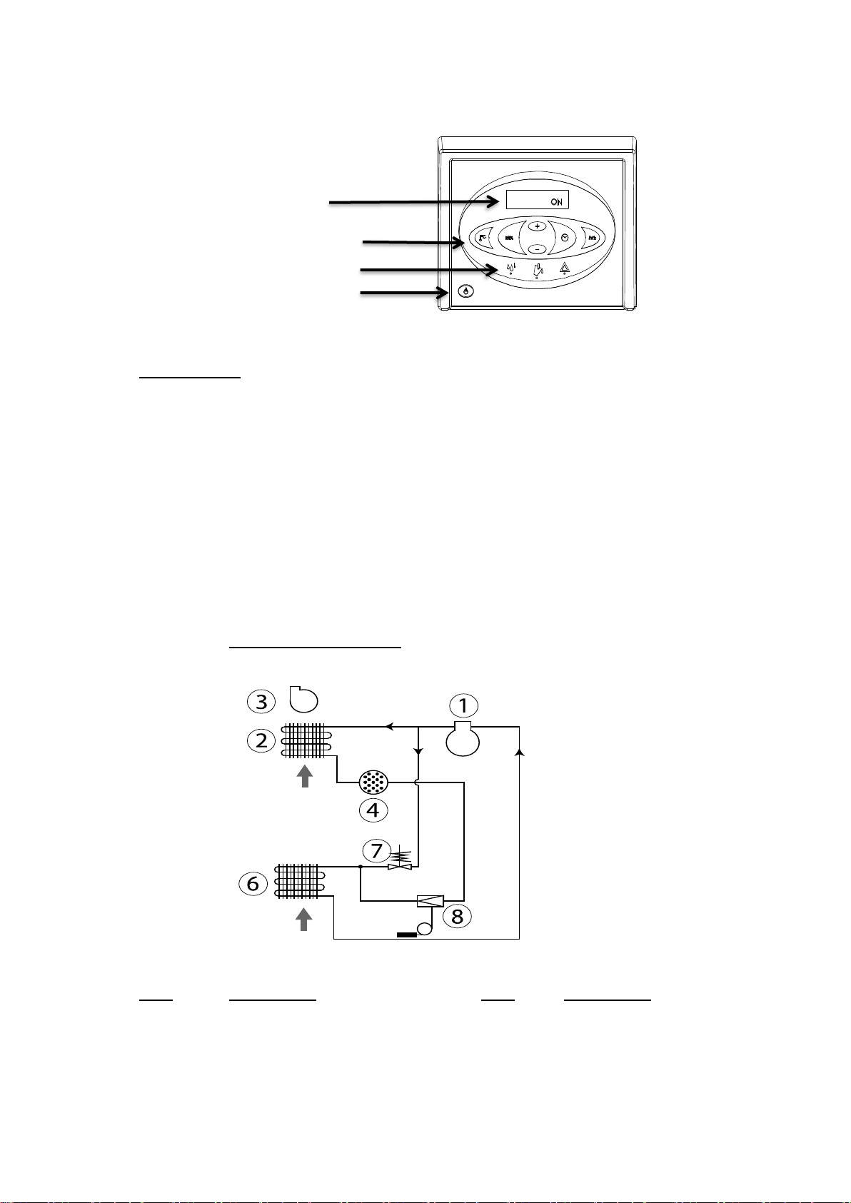
Principles of The following describes the air flow
operation: through the dehumidifier:
The air flow through the
dehumidifier.
A fan draws in humid air through a
filter to the dehumidifier
The air is cooled down and
humidity/water drops are led down
to the water tank
The air is re-heated by e.g. the
operation of the dehumidifier (approx.
increase in temperature is + 5 °C)
Due to the repeated air circulation through the dehumidifiers, the air humidity is
continuously reduced whereby achieving rapid, but gentle drying.
Illustration: This illustration gives an overview of the dehumidifier:
Handle
Touchscreen
Power cable
Air outlet
Supply air inlet (PPI
filter behind the grille)
Water tank
Wheel
Serial plate behind
the water tank
Front view Rear view
Water tank: Water is collected in the water tank. Alternatively, you can also setup the dehumidifier for
permanent drainage with the adapter for hose connection (accessories, see page 14).
When the water tank is full, the dehumidifiers shut off automatically.
Emptying of the water tank, see manual, page 13.
Operation of the unit is not possible once the water tank is removed.
4 of 33

Product- and functional description
Illustration: This illustrates the operator control:
Display/
Operator Control
Display
Function buttons
Status display
Main switch
Fig. 4
Functions: Main functions
• Manual or automatic operation (built-in adjustable hygrostat)
• Socket for external hygrostat
• Display for temperature, relative humidity, hour meter and kW/h-consumption
• Hour meter and display for consumed kW/h without 230V-connection
• Adjustable service interval counter
For correct operation look at the detailed instructions in this manual.
Cooling KT 330, KT 430, KT 830
Circuit
Diagram:
Pos. Description Pos. Description
1 Compressor 6 Vaporizer
2 Condenser 7 Solenoid valve
3Fan 8 Thermic expansion valve
4 Filter 5 of 33

Set up and transport of the unit
Introduction: This section provides information required for:
unwrapping the unit, making it ready for use and transportation of the unit.
Warning: If the dehumidifier has been laid down during transport, it is imperative to place it in
upright position for at least one hour before put into service!!!
Procedure: Follow these steps to unwrap the unit and make it ready for use:
Step Action Illustration
1 Open the cardboard box
on the top.
2 Place the cardboard box so
that the handle and wheels
are on the floor.
3 Pull the handle and wheel
of the dehumidifier out while
lying down.
4 Loosen the finger screws
and pull the handle up to the
desired height and tighten
the finger screws again.
5 Remove the protective film from the control panel.
Placing: Placement of the dehumidifier
Place the dehumidifier at a spot with good air circulation, where the minimum distance
from the air intake side should be 60 cm to the wall and from the air outlet side 3 m.
Also remember:
•The ventilation openings must be kept free during operation.
6 of 33

Set up and transport of the unit
Location Since the appliances contain a flammable refrigerant, the following requirements for
requirements:
the location must be fulfilled.
•The device must be installed, operated
and stored in a room with a area larger than
than 4 m².
Check whether there are any local regulations
that you have to obey when installing
or storing of the device.
•The device must be stored in a well-ventilated area, with the
room size must correspond to the room areas of 4 m².
•The device must be installed in a room without permanently
active ignition sources (e.g. open fire, a gas appliance in operation or an
electric air heater in operation).
Optimal Make sure that the room to be dehumidified is closed and the device is not
operation: placed near a heat source, such as e.g. a radiator.
Electrical The dehumidifier is complete with a cable and plug and ready for connection to a
connection: 230 V / 50 Hz socket. Protect the socket with a 10 A fuse or a 16 A circuit breaker.
Warning: If the power cord is damaged, it must be replaced by the manufacturer,
maintenance service or similarly qualified persons in order to avoid danger.
7 of 33

Set up and transport of the unit
Wheels The wheels are mounted so that the unit can easily be pulled upstairs without damaging
the housing or the stairs.
Transport/- The dehumidifier can be lifted by two persons or with a crane, see instructions below:
Replacing Note: Observe local working environment rules regarding heavy lifting.
of the
dehumidifier:
Hoist/Crane
Lift by lifting strap.
Stacking: Max. 2 dehumidifiers should be
stacked on top of each other.
Stacking of 2 dehumidifiers
only – as illustrated.
Press the handle of the lower
dehumidifier to the bottom
before stacking. The handle
then fits into a notch on the
upper dehumidifier.
8 of 33
2 People

Operating Manual
On-/Off- The following table shows the operation of the on-/off-function and the display texts
Switching and
operating status
Push button Display
ON Continuous operation
INT HYG ON Operation controlled by internal hygrostat
INT HYG STOP ,if the preset value of the internal hygrostat
is reached
EXT HYG ON operation controlled by external hygrostat
EX HYG STOP ,if the preset value of the external hygrostat
has been reached
Switching off
The green LED shows active dehumidification.
Operation of The following table shows the operation of the hygrostat function and the display texts
the built-in
hygrostat Step Button
keep
HYG SET RHXX% - flashes for 5 seconds.
pressed The dehumidifier then switches to the controlled operation with
setpoint - when the setpoint is reached,
the following appears on the display:
INT HYG STOP
press Shortly press +/- in order to set the RH%-value in the
(if it mentioned 5 seconds. The new value will be stored after a
flashes) further 5 seconds, when the last button is pressed.
hold
HYG SET RHxxx% - flashes for 5 seconds.
down The dehumidifier switches to continuous operation.
1 x press
HYG Off will flashes. The setting is stored after 5 seconds.
(if it The dehumidifier then switches to the continuous operation.
flashes) 9 of 33
Explanation

Operating Manual
Operation of If an external hygrostat has been connected the unit automatically changes to operation
an external with this hygrostat.
hygrostat Changes of the preset value can be done only on the external hygrostat.
(If the preset value has been reached the display shows: EXT HYG STOP)
Hour meter: The built-in hour meter counts the total operating hours (can not be reset) as well as
the hours until the next service which can be changed. The service hour meter is
switched off when the unit is delivered.
Step Button
keep
SERVICE xxxxh – shows the hours until next authorised service.
pressed
This value is automaticly stored after 5 seconds of flashing and the
function is activated if not already done. When the time for the
service intervall has been reached the display shows: SERVICE.
Shortly press +/- in order to preset a new service interval.
The new value will be stored 5 seconds after pressing of the
last button.
Hold down
Servive xxxxh - shows the hours until next authorised
until it service.
flashes
1 x press
SET SERVICE OFF - switches the servicetimer function off.
(if it The new value will be stored 5 seconds after pressing the last
flashes) button.
Display texts The following table shows how to operate the operating informations.
Button
XX°C shows the ambient temperature
Actual RH% shows the actual relative humidity
XX kWh shows the total energy consumption
Cannot be reset
xxxxh shows the total operating hours
Cannot be reset
10 of 33
Explanation
Explanation

Operating Manual
Text displays The dehumidifier has a built-in battery which makes it possible to read the display also
without if not connected to a power supply. Without main power the following can be read:
main power
Button
keep pressed
and shows the total energy consumption in kWh
press once
keep pressed
and shows the total operating hours
press once of the dehumidifier
Exchange of If the hour meter is separated from the power supply and can no longer be read then
the Data the cause is most probably an empty data store-battery.
store-battery
Procedure how to exchange the battery:
Warning:
Before exchanging the battery make sure that the dehumidifier is disconnected from the
power supply.
1.
11 of 33
Measure
Loosen screws on both sides
of the touchscreen and lift
the touchscreen carefully.
Explanation

Operating Manual
2. Cut the cable strap which holds the battery.
Exchange battery and use a new maximum
2,5 mm wide cable strap.
Use only batteries of type Alkaline AAA.
Illustration of circuit board with battery in the wiring diagram
on page 33.
Fault An overview of possible faults which make a normal operation impossible.
informations
Illustration Fault information Cause Remedy
Yellow light on middle The water tank is full see instructions for
LED with emptying or malfunction at the emptying below resp.
symbol and water pump (accessory) check pump drainage
FULL on display
Red light on Pressure or temperature in the Check filter and
right warning-LED high-pressure element dehumidifier for dirt in
HIGH Temp on display too high the airstream
Red light on Room temperature Place dehumidifier in
right warning-LED above normal operating specified temperature
AMBIENT TEMP sector sector of 3°-35°C
on display
Red light on
right warning-LED
1. EVAP FAIL Call for authorized
SENSOR FAIL on display Thermo sensor of service technician
One of the internal evaporator defective
sensors is defective 2. COND FAIL Call for authorized
Use +/- buttons in order to Thermo sensor of service technician
change between the condensor defective
3 possible faults 3. ROOM FAIL Call for authorized
Built-in roomtemperature service technician
sensor defective
Red light on Leak in the cooling Call for authorized
right warning-LED circuit service technician
LP STOP
on display 12 of 33
Sensor Fail

Emptying the It is not necessary to shut down the dehumidifier when emptiying the water tank.
water tank The dehumidifier shuts down automatically when the water tank is removed.
Follow the procedure to empty the water tank:
Step Illustration
1 Pull the handle in front of the water tank to remove
the tank halfway out of the dehumidifier.
2 Grab the side handles of the tank and lift
clear off the dehumidifier.
3 Tilt the tank sideways to pour the water out
through the side opening.
4 Put the tank back in place.
IMPORTANT !!!!!!
Check that the water tank is correctly
positioned.
13 of 33
Operating Manual
Measure

Accessories
Introduction Further information about each separate accessory is available on request to
Hans Wilms GmbH & Co. KG
List Below you will find a complete list with drawings, description and article numbers of
accessories available for the units:
Accessory Drawing Description KT-Type Part.-No.
Hygrostat When a hygrostat is connected the
dehumidifier can operate continuously
depending on the relative humidity in
the room.
Hygrostat with 1,5 m cable and all 3102004
jack plug.
Tap and Ball tap and brass screwed
screwed KT 830 -
hose
direct drain of condensate water.
connector
Condensate Using a condensate pump, KT 330 3103756
pump no emptying of the water tank
KT 430 - KT 830
3103755
is necessary.
14 of 33
KT 330 - KT 430 - 3103750
hose connector and clamp for

Warnings Proper maintenance of the unit is necessary in order to achieve trouble-free operation.
Important! Always disconnect the power cable from the unit before doing any preventive
maintenance.
This product contains a flammable refrigerant. Before working on the system,
carry out security checks to reduce the risk of fire to a minimum.
•No open fire.
•No electrical ignition sources (open electrical contacts).
•No mechanical ignition sources (grinding processes).
•No combustible material near the workplace.
•Good ventilation of the area.
•Check the presence of refrigerants.
Other security measures
•Technicians and others working on site must be instructed in the nature
of the work to be carried out.
•The area around the workstation must be separated.
•Place a "No Smoking" - sign around the separation.
If hot work must be carried out on the refrigerant equipment or other related parts,
you have to have suitable fire extinguishing equipment at hand.
(Powder extinguisher A,B,C. CO2 extinguisher.)
Inspection The inspection checklist has been developed for operators for preventive maintenance.
by the No special skills are required for this service check. The checklist contains information:
operator:
•which components need to be inspected.
•
on the frequendy of inspection (Annual, Monthly, Weekly, Daily).
•how the inspection is to be carried out.
•criteria for acceptance or non-acceptance.
Annual Return the dehumidifier to an authorised service centre at the end of the service interval or
maintenance
or at least once a year.
or
The device is carefully maintained and inspected there, for leaks in the cooling system
maintenance
and tested for electrical safety.
according to Wilms also offers fixed service contacts where these devices can be repaired.
service For more details, please contact your nearest Wilms dealer.
interval
counter:
15 of 33
Preventive Maintenance

16 of 33
Checklist User

17 of 33
Checklist User

18 of 33
Checklist User

19 of 33
Checklist User
This manual suits for next models
3
Table of contents
Other WILMS Dehumidifier manuals