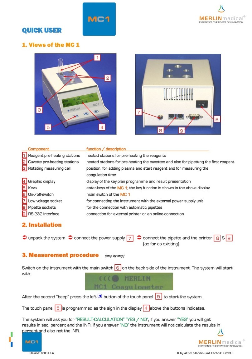
Merlin medical MC10 PLUS User manual

O P E R A T I O N M A N U A L
Instrument Manufacturer:
ABW Medizin und Technik GmbH&Co KG
Lagesche Str.15
32657 Lemgo
Germany
MC and MERLIN are registered trademarks of ABW Medizin und Technik GmbH & Co KG
IVD
www.merlinmedical.
net
Release 16_77

© 2004-2020 ABW Medizin und Technik, D-32657 Lemgo
This manual including all its parts is copyrighted. Any deployment beyond the strict rules of the
copyright law is prohibited and liable to prosecution without prior allowance of ABW Medizin und
Technik GmbH & Co KG. This applies especially for copying, translating, microfilming and storing
and data processing in electronic systems.
Registered trademarks and names are usually not indicated as such. The absence of such marking
does not mean that it is a free name in the sense of the trademark law.

SAFETY INSTRUCTIONS
Symbols used on the MERLINmedical haemostasis instruments and consumables
Symbol Meaning Used on / in
Do not reuse Balls & cuvettes
In-Vitro Diagnostics Device Operation manuals
Biological risks
MC 1
MC 4plus
MC 10plus
Consult instructions for use
MC 1
MC 4plus
MC 10plus
LOT Batch code number Balls & cuvettes
Manufactured by
MC 1
MC 4plus
MC 10plus
Use by date:
YYYY-MM Balls & Cuvettes
Temperature limits for storage Balls & Cuvettes
Label
”serial number” Back of instrument
MC 1
MC 4plus
MC 10plus
Power supply unit
2
IVD

1
TABLE OF CONTENTS
1. Introduction ........................................................................................................................... 3
1.1 ........ Guarantee ......................................................................................................................... 3
1.2 ........ Purpose of use .................................................................................................................. 4
1.3 ........ Specifications .................................................................................................................... 4
1.3.1 ..... Correlation, precision & verification .................................................................... 4
1.4 ........ Measuring principles ......................................................................................................... 5
1.4.1 ..... Mechanical measuring principle .......................................................................... 5
1.4.2 ..... Optical measuring principle ................................................................................. 5
1.5 ........ Specifications .................................................................................................................... 6
1.6 ........ Views of the MC 10plus ....................................................................................................... 7
1.7 ........ Views of a 3-Volumen-microliter pipette .......................................................................... 9
1.8 ........ Views of a HandyStep® pipette ........................................................................................ 10
2. Installation ............................................................................................................................ 11
2.1 ........ Unpacking ....................................................................................................................... 11
2.2 ........ Content / Scope of delivery ............................................................................................ 11
2.3 ........ Consumables and accessories ......................................................................................... 11
2.4 ........ Location of the instrument ............................................................................................. 12
2.5 ........ Connections demand ...................................................................................................... 13
2.6 ........ Connection of the device ................................................................................................ 13
3. Function .................................................................................................................................. 14
3.1 ........ Menu structure ............................................................................................................... 14
3.2 ........ Performance test ............................................................................................................ 15
3.2.1 ..... Testing of a measurement resp. of an incubation .............................................. 17
3.3 ........ Test parameter ............................................................................................................... 19
3.4 ........ Test evaluation / calculation ........................................................................................... 21
3.4.1 ..... Mechanical measurements (ball method) ......................................................... 21
3.4.2 ..... Optical measurements ...................................................................................... 22
3.5 ........ Settings menu ................................................................................................................. 24
3.5.1 ..... Date and time ................................................................................................... 24
3.5.2 ..... Factory settings ................................................................................................. 25
3.5.3 ..... Software version ............................................................................................... 25
3.5.4 ..... Language ........................................................................................................... 25
3.5.5 ..... Print setting ...................................................................................................... 25
3.5.6 ..... Print result lists ................................................................................................. 25
3.5.7 ..... Barcode scanner ................................................................................................ 25
3.5.8 ..... Online setup ...................................................................................................... 26
3.5.9 ..... Measurement settings ...................................................................................... 26
3.5.9.1 .. ......... Forced incubation ................................................................................... 26
3.5.9.2 .. ......... Channel auto reset .................................................................................. 26
3.5.9.3 .. ......... Interval mode.......................................................................................... 27
3.5.9.3.1 ......... Waiting time ........................................................................................... 27
3.6 ........ Patient memory .............................................................................................................. 27
3.7 ........ Service menu .................................................................................................................. 28
4. Pipetting technique .......................................................................................................... 29
4.1 ........ Precision and correctness ............................................................................................... 29
4.1.1 ..... Pipetting with a microliter pipette .................................................................... 29
4.1.2 ..... Volume selection on automatic microliter pipette ............................................ 30
4.1.3 ..... Pipetting with a HandyStep® dispenser ............................................................. 30

2
4.1.4 ..... Volume selection on the HandyStep® dispenser ................................................ 30
4.2 ........ Sample absorption (microliter pipette) ........................................................................... 31
4.3 ........ Sample dispensing (microliter pipette) ........................................................................... 32
4.4 ........ Dispension of reagent 1 (microlitre pipette or HandyStep® pipette) ............................... 33
4.5 ........ Dispension of start reagent (microlitre pipette or HandyStep® pipette) .......................... 34
5. Operation ............................................................................................................................... 35
5.1 ........ Keyboard layout ............................................................................................................. 35
5.2 ........ Switch on the device ....................................................................................................... 35
5.3 ........ Measurement of parameters with one reagent component ........................................... 37
5.4 ........ Measurement of parameters with two reagent components .......................................... 39
5.5 ........ Measurement of parameters in the optical test position ................................................ 40
5.6 ........ Stopping of an incubation time ....................................................................................... 41
5.7 ........ Stopping after a mistakenly start of a measurement ...................................................... 41
5.8 ........ Switch off the device....................................................................................................... 41
6. Warning hints for the operation ............................................................................... 42
7. Handling hints ..................................................................................................................... 43
7.1 ........ Handling of the reagent .................................................................................................. 43
7.2 ........ Handling of the cuvettes ................................................................................................. 43
7.3 ........ Handling of the testing material ..................................................................................... 43
8. Quality control .................................................................................................................... 44
9. Maintenance ........................................................................................................................ 44
9.1 ........ Maintenance by user ...................................................................................................... 44
9.2 ........ System self-test .............................................................................................................. 45
9.2.1 ..... Automatic self-tests after switching on the device ............................................ 45
9.2.2 ..... Cycle tests during measuring mode ................................................................... 45
10. Errors ........................................................................................................................................ 46
10.1 ...... Analytical errors ............................................................................................................. 46
10.2 ...... System errors .................................................................................................................. 51
11. Addition printer.................................................................................................................. 52
12. Barcode Scanner ................................................................................................................ 52
13. Appendix I Verification document ....................................................................................... 53
14. Appendix II Declaration of conformity ................................................................................. 54
Before using the MC 10plus study the instruction manual carefully.
This manual shall convey you an extensive comprehension for the operating mode of the
MC 10plus for enabling you to use all functions of the device.
Reproduction of this manual
This document contains proprietary information that is protected by copyright. All rights are
reserved. No part of this document may be photocopied, reproduced, or translated to another
language without the prior written consent of ABW Medizin und Technik GmbH & Co KG.

3
1. Introduction
1.1 Guarantee
The company ABW Medizin und Technik GmbH, called ABW in the following, grants the first buyer that
the of ABW purchased instruments are free of material and processing failures under normal utilisation.
This guarantee applies for one year as of date of invoice of the first purchase (the “period of
guarantee”).
Should failures occur within the period of guarantee please contact the ABW-customer service
immediately (Fon: +495261_927 294). When contacting the customer service important information as
e.g. the detailed description of the defect as well as instrument type and ID-number of the MC 10 plus
have to be communicated.
The customer service is available for questions concerning guarantee from Monday until Friday from
8:30 a.m. until 5:00 p.m. (public holidays excluded). ABW charges the customer for repair of defects
beyond the period of guarantee as well as for the repair of defects which are not covered by the
guarantee according to the at that point of time valid costs for work and material.
Following defects which essentially require a repair are excluded from this guarantee:
Defects which are
a) not within the period of guarantee and not communicated within one
week after occurring to ABW
b) caused by chemical decomposition or corrosion
c) described in the manual of ABW
d) the consequence of maintenance works, repairs or modifications of not
by ABW authorised staff
e) caused by an application beyond the intended purpose or by an
accident.
The liability of the manufacturer for any kind of damages due to the delivery, installation, application,
repair and maintenance of the instrument within or beyond this guarantee is - at ABW’s own discretion -
restricted exclusively to the repair or to the replacement of the instrument. ABW is not liable for the
injury of third persons, secondary or consequential damages or losses in profit.
The replaced parts become automatically property of ABW.
The of ABW manufactured instruments may only be used with power supply units which are supplied by
the manufacturer and which are expressively intended for this use.
THE ABOVE GUARANTEE IS THE SOLE WARRANTY FOR THE INSTRUMENT OF ABW. ALL OTHER
EXPRESSLY OR SILENT PROMISES, INCLUDING PROMISES WITH REGARD TO THE MARKET SUITABILITY OR
THE SUITABILITY FOR A CERTIN PURPOSE ARE EXCLUDED.
© by ABW Medizin und Technik GmbH & Co KG 2020

4
1.2 Purpose of use
The MC 10plus is a semi-automatic mechanical and optical (optionally) detection system which is used for
the determination of prothrombin times (PT), activated partial thrombo plastin times (aPTT) and
fibrinogen concentrations as well as other clotting and chromogenic tests whereas the output are
measuring results in view of quality. In connection with suitable reagents plasmas and also full blood
specimen can be measured.
The sample and also the reagents are added manually with a suitable calibrated pipette. The time
keeping until the detection of the coagulation is done automatically. On the base of correct parameters
and correct entering of the curves the coagulation times are converted into corresponding results.
1.3 Performance data
The precision of the tests carried out with the MC 10plus is not depending on the instrument but on the
sample receipt, sample handling as well as the precision of the employed sample and reagent
distribution system.
1.3.1 Correlation and precision
An investigation for the evidence of the equivalence of the MC 10plus to another commercial mechanical
coagulation analyser has been done by a nameable German reagent producer with PT-, aPTT-, Fib-, TZ-,
AT3- and D-Dimer measurements. Please ask ABW to get more information.

5
1.4 Measuring principles
1.4.1 Mechanical measuring principle
Special cuvettes with a steel ball inside are place on the measuring positions in instrument related racks.
As the measuring block is sloping slightly the ball always remains due to gravity at the deepest point of
the cuvette. In the height of this point there is a magnetic sensor. At first the sample is pipetted into a
measuring cuvette, then – if required – the first reagent is added and the incubation is started. The
instrument turns the cuvette with the adjusted speed around the longitudinal axis. When the incubation
is finished (parameter specific) the start reagent is added and the measurement is start simultaneously.
When the coagulation begins the growing clot pulls the ball out of the basic position and the magnetic
sensor detects a magnetic impulse which causes the end of the measurement.
1.4.2 Optical measuring principle
The photometry is basing on the fact that a part of the passing light (UV-VIS = UV and visible field ca. 200
- 900 nm wave length) is reduced through the liquid test sample. Here the own colouration of the probe
or the colouration of the probe by adding suitable reagents is used.The course of the colouration is
stored in the MC 10plus and evaluated by a special software according the test requirements.
photometer principle: plasma before plasma after
clot formation clot formation
cuvette
measuring
block
ball
sensor
measuring
cell

6
1.5 Specifications
Type : Coagulation analyser / bench top device
RS 232 : unidirectional
Measuring principle : mechanical + optionally optical measuring method
Number of measuring channels : 10 + 1
Display : graphic presentation
Sample pipetting stations : 20 (2 racks with each 10 cuvettes; at room temp.)
Cuvette pre-heating stations : 10 (1 rack with 10 cuvettes)
(if required also employable as
reagent pipetting station)
Pre-heated storing position for
start reagent pipette : 2
Pipette storing position at
room temperature : 1
Drills 14.5 x 85.0 mm : 5
for reagent pre-heating
Drills 11.5 x 75.0 mm : 5
for reagent pre-heating
Dimensions : 430 x 590 x 170 mm (L-W-H)
Weight : 15 kgs
Power primary : 100 VAC - 240 VAC
50 / 60 Hz
Power secondary : 24V
Power consumption : 70 VA
Measuring block temperature : 37.3°C (+/- 0.5°C)
Measuring period : 4.5 – 999.9 seconds
Motor turning speed : MC 10plus micro 50 r.p.m.
MC 10plus macro 40 r.p.m.

7
1.6 Views of the MC 10plus
Component Function / Description
1. Sample pipetting pre-pipetting for further measurements
2. Graphic display display of the keyboard layout, programme and result
display
3. Function keys keys for data entering, their functions are shown in the
display above
4. Start pipette different kinds of start pipettes can be used (red storing
position = heated).
5. Optical measuring position (as option) for diverse chromogenic tests
6. Signal lamps with activating keys depending on the condition of the system respectively of
the measuring positions above green, yellow or red
7. Reagent and cuvette reagent pre-heating positions for reagent and
pre-heating station cuvettes and for the preparation of the intended tests
8. Measuring positions position in which the start reagent is added and which
the clotting time is measured
8
6
4
2
3
1
5
7

8
Component Function / Description
1. On- / off-switch main switch of the MC 10plus
2. Low voltage socket for connecting the instrument with the external power
supply unit
3. Pipette sockets for the connection of automatic pipettes with contact
line
4. RS 232 interface plug-in for external printer
5. Barcode scanner connection for external barcode scanner
6. PC online-connection for the purpose of Software Updates
7. LIS online-connection for external laboratory EDP
1
2
3
6
4
7
5

9
Laboratory Information System
1.7 Views of a 3-volume microlitre pipette
Component Function / description
1. Pipetting key For filling and dispensing start reagent. If a measuring
position activating key has been pressed at the MC
10plus the time keeping can be started by pressing the
pipetting key until the first stop.
2. Pipette contact line For the connection of the automatic pipette with the
analyser.
3. Ejector cap Removing of used pipette tips
4. Switch for volume selection When the pipetting key (no.1) is pushed down
completely the pipetting volume can be adjusted with
this switch (50, 100 or 200 µl)
1
2
3
4

10
1.8 Views of a Handystep pipette
Component Function / description
1. Dispensing lever For dispensing reagent. If start reagent has been
absorbed and a measuring position activating key has
been pressed at the MC 10plus the time keeping can be
started by pressing the dispensing lever (automatic
pipette).
2. Locking / Filling lever For absorbing reagent. For inserting a combitips pull
down
3. Sliding switch for volume selection For adjusting the pipetting volume (please see pipette
back)
1
2
4
3

11
4. Combitip Adjust volume of the combitips and adjust the sliding
switch for volume selection (no. 3) to pipetting volume

12
2. Installation
2.1 Unpacking
The MC 10plus is transported in a cardboard which shall protect the instrument from transport
damages. Remove the analyser and the accessories carefully from the cardboard. If you detect
any obvious damages you have to record them on the delivery note. The carrier and your ABW-
contact person have to be informed accordingly and immediately.
2.2 Content / Scope of delivery
Please take care that following items have been delivered:
MC 10
plus
coagulation analyser
Power supply unit
Power cable
2 Sample racks
2.3 Consumables and accessories
Consumables / description
Cat.
-
No.
Packing unit
MC cuvettes and balls micro
Z0512
0
1,000
MC cuvettes and balls macro
Z05100
1
,000
Reagent tubes plastic (14.5 mm x 80.0 mm)
83
2158
3
0
0
Coagulometer tubes plastic
83
3118
500
Thermo paper
851057
5
Accessories / description
Cat.
-
No.
Packing unit
Automatic pipette Handystep
®
with start cable
P20010
1
Ball dispenser micro
Z11000
1
Ball dispenser macro
Z10000
1
Printer
H10000
1
Sample holder MC 10
C00300
1
CoagView
®
-
Software (for data transmission)
S20000
1
Lysis
-
Programme (for Lysis
-
evaluation)
S10000
1
Barcodescanner
240001
1
The in 2.3 Consumables and Accessories mentioned articles are not part of the MC 10plus scope
of delivery. The comsumables can be ordered according to the user’s requirements. An
automatic pipette ensures that the time keeping is started simultaneously with adding the start
reagent. If the manual start key is used for starting the time keeping the reagent can be
dispensed with any pipette which can dispense the correct volume for the according test.

13
2.4 Location of the instrument
1. Place the MC 10plus on a plane, stable, vibration- and dust-free work surface which is deep and
wide enough to ensure the air circulation of the instrument. For ensuring a sufficient cooling of
the analyser the distance between instrument and wall respectively to another object has to be
at least 10 cm. The instrument should not be placed next to centrifuges or other instruments
which could cause vibrations.
Minimum space requirements:
- width 79 cm (width of the instrument: 59 cm)
- depth 53 cm (depth of the instrument: 43 cm)
2. Position the MC 10plus in an area with low humidity and little variations in temperature. The
device should not be placed directly under ventilation shafts which cause strong draughts.
3. Place the MC 10plus in an area which is protected from direct sun light.
4. The distance between the analyser and the socket may not exceed 3 m. Other instruments with
high power consumption and which are frequently switched on and off as e.g. centrifuges, air
conditionings or refrigerators should not be connected to the same circuit. When switching on
and off such instruments the voltage drop can be strong enough to have a negative effect on the
proper operation of the MC 10plus.
Attention!
If the user is electrified a discharge may happen at the MC 10plus. This
discharge has no influence on the function of the MC 10plus.

14
2.5 Connection demands
1. Before the electrical installation is carried out it has to be ensured that the operating voltage of
the supplied power supply unit corresponds with the existing mains voltage (100 VAC – 240
VAC).
2. Only employ the with the MC 10plus supplied suitable external power supply unit, otherwise the
analyser could be damaged.
3. It is recommended that all repairs beyond the periodical maintenance and little setting are
carried out by the ABW-customer service.
4. If the instrument is not used as advised in the manual the safe operation is not granted and the
guarantee expires.
5. The instrument may not be connected to an extension lead.
6. The total length of the mains connection may not exceed 3 meters.
Warning!
Only the original external power supply (100 VAC – 240 VAC) which is
delivered with the MC 10plus may be used, otherwise the analyser
could be damaged.
2.6 Connection of the device
1. Connect the low voltage cable of the power supply unit with the low voltage plug at the back of
the instrument.
2. Insert the plug of the power supply unit into a socket.
3. If an automatic pipette is used connect the pipette contact line to one of the according sockets
at the back of the MC 10plus.
4. If an additional printer is used connect the data line of the printer with the RS-232 interface
(chapter 1.6).
or If you require an online connection then the EDP-data line has to be connected with the RS-232
interface.
5. The data line for the external printer or for the online connection may not be longer than 3
meters.
6. If an external barcode scanner shall be used connect the contact line of the scanner with the
socket for the scanner (chapter 1.6).

15
3. Function
3.1 Menu structure
(Version 1.7: 11.03.2007)
Switch on
Select test
PT
PTT
FIB
TZ
FAK
FP 1
FP 2
FP 3
Emergeny
Photometer
Quit
Workmode Menu
Running number
Input patient ID
Emergency
Quit
Measure mode
Start menu
Measure mode
Testparameter
Settings menu
Patient memory
Service menu
Welcome display:
MERLIN MC 10plus
Testparameter (PIN)
PT
PTT
FIB
TZ
FAK, FP1, FP2 and FP3:
Emergency
Photometer
Settings-Menu (PIN)
Date and Time
Adjustment of date
and system time
Default-Parameters
Load default settings
Software-Version
Language)
- English
- German
- Chinese
Print settings
Print the settings of the
settings-menu
Print result list
Search results in the
memory and print them
resp. send them online
Barcode-Scanner
Adjust / select barcode
scanner
Online Setup
Adjust parameter for
data transmission
Measure setup
Force incubation
meas.ch. auto reset
Suggest patient-ID
Interval-mode
Quit
Quit settings-menu
Running number
Test PT
Input
starting no.:
1
Patient memory
Search Pat.ID
Print by Pat.ID
Print by date
Send online by Pat.ID
Send online by date
Delete
Quit

16
3.2 Performance test
The correct operation of the instrument should be examined by means of a performance test
prior to the intended use of the analyser.
All functions of the MC 10plus are called up with the control keys below the display.
Ensure that no used cuvette is in the optical measuring position.
Switch on the MC 10plus at the on / off-switch at the back side.
The MC 10plus makes a signal tone and the display is lighted up and the signal lamps under the
measuring positions light up yellow-orange. Watch the display.
After approx. 15 sec. the display changes automatically from the welcome display to the start
menu. The signal lamps do no longer light up.
Start menu
Measure mode
Test parameter
Settings
-
menu
Patient memory
Service menue
Select „Measure mode“ by means of the arrow keys and confirm by pressing the ENTER-key. You
have to communicate the MC 10plus now in the work mode menu whether a running number or
a Pat.-ID shall be used for the sample test result identification.
In addition to these possibilities an urgent sample can be defined as “Emergency“, for which two
parameters have been defined before (chapter 3.3) in order to ensure a quickest possible
measurement.
Workmode menu
Running number
Input Pat.
-
ID
Emergency
Quit

17
Select the required patient definition with the arrow keys and confirm with ENTER.
Now defined which test shall be carried out. You can select the according parameter with the
arrow keys and confirm your selection with the ENTER-key.
Select test
PT
PTT
FIB
TZ
FAK
FP 1
FP 2
FP 3
Quit
If you wish to work with a running number for the sample identification you have to enter a start
number for the first sample to be measured. The MC 10plus suggests number one. (if an
identification via Pat.-ID is required skip the next display).
Running number
Test:
PT
Input starting no.:
1
Confirm the input with the ENTER-key. Then you get automatically to the measuring
programme. Here the signal lamps light up green constantly.
Measuring mode
TEMP = 37.3°C
MZ
Pat.
-
ID
PROG
TIME
RESULT
INFO
1
STOP
12
STOP
13
STOP
14
STOP
15
STOP
16
STOP
17
STOP
18
STOP
19
STOP
20
STOP
21
INIT
F1 = AUTO
F3 = DELETE
A measurement can not be started before the measuring block has reached the programmed
temperature. If the temperature is not yet reached then “TEMP” will flash in the upper right
corner when you try to start a measurement.
Table of contents
Other Merlin medical Measuring Instrument manuals
Popular Measuring Instrument manuals by other brands
Anritsu
Anritsu VectorStar ME7838 4X Series Maintenance manual
Fluke
Fluke VR1710 quick start guide
Tektronix
Tektronix MSO 4 Series Quick start manual
Moeller
Moeller Xcomfort CTEU-02/01 Assembly instructions
Landis+Gyr
Landis+Gyr ULTRAHEAT XS operating instructions
Hanna Instruments
Hanna Instruments C 215 instruction manual
