3
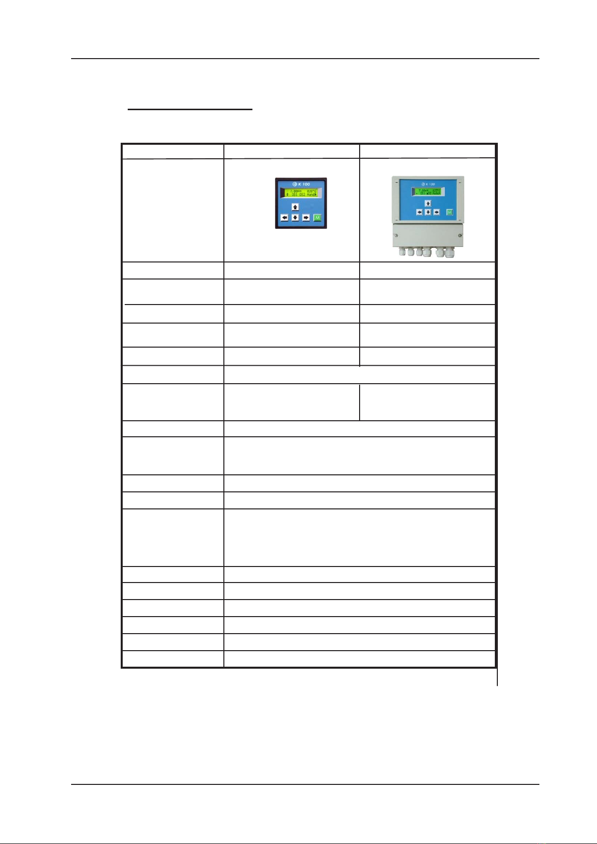
K 100 PR & K 100 W PR
Contents
1. Your K 100 ..................................................................................................... 4
1.1GeneralandSafetyinstructions ...............................................................5
1.2Features...................................................................................................6
1.3Technicaldata ..........................................................................................7
1.4DeclarationofEGconformity....................................................................8
2. Instructions for installation and connections .............................................9
2.1Dimensions ............................................................................................ 10
2.2 Installation K 100 ................................................................................... 11
2.3 Installation K 100 W ............................................................................... 12
2.4ConnectiondiagramK100 PR ............................................................... 13
2.5 Connection diagram K 100 W PR........................................................... 14
3. Operation of the instrument....................................................................... 15
3.1Howtoadjustparameters....................................................................... 16
3.2Menuoverview ........................................................................................ 17
4. Password and language ............................................................................ 18
5. Adjustments for measurement .................................................................. 19
5.1 Calibration .............................................................................................. 20
5.2Temperaturecompensation .................................................................... 21
5.3ORPmeasurements............................................................................... 22
6. Adjustments of the controller .................................................................... 23
6.1ON/OFFcontroller.................................................................................. 24
6.2P / PI controller as impulse-frequency controller..................................... 25
6.3 P / PI controller as pulse-pause controller .............................................. 26
6.4Activationanddeactivationofthecontroller............................................. 27
6.5Turn-ondelay ......................................................................................... 27
6.6 External controller stop .......................................................................... 27
6.7Manualoperationoftherelays................................................................ 28
6.8LimitvaluesandAlarm ........................................................................... 29
7. Data output.................................................................................................. 30
7.1Currentoutput ........................................................................................ 30
7.2SerialinterfaceRS485(option) ............................................................... 30
8. Operation and maintenace........................................................................ 31
9. Service ........................................................................................................ 32
9.1Productinfo............................................................................................ 32
9.2Analoginputs ......................................................................................... 32
9.3 Erase settings (reset)............................................................................. 32
10.Errormessages ......................................................................................... 33
Index ............................................................................................................... 34