Lasermet ICS-6 User manual

ICS Contactors Wiring Manual
01518-53-000 Issue 2 13 January 2020
LASERMET
WIRING CONTACTORS
TO AN ICS-5 OR ICS-6
WIRING MANUAL
Issue 2

ICS Contactors Wiring Manual
01518-53-000 Page 2 of 8 Issue 2 13 January 2020
LASERMET ICS Contactors
Wiring Manual
Contents
1 Safety Warnings .................................................................................................................. 3
2 Concept ............................................................................................................................... 4
3 Testing ................................................................................................................................ 6
4 Specifications ...................................................................................................................... 7
5 Warranty ............................................................................................................................. 7
6 Contact Details .................................................................................................................... 8

ICS Contactors Wiring Manual
01518-53-000 Page 3 of 8 Issue 2 13 January 2020
1 Safety Warnings
This device is intended to be used as part of a safety system which may be used to protect personnel
and equipment from possible injury, damage, or loss.
As such it must be installed and wired according to these instructions and tested by suitably qualified
persons. No attempt may be made to tamper with the parts, open them, or use them outside of the
parameters contained herein.
The units are only designed to be fixed to surfaces using their inbuilt fixing holes. They must not
come into contact with each other or any other moving part when in use. The parts should never be
subject to impact or mechanical strain.
Safety switches should never be defeated or bypassed. It is imperative that all steps are taken to
ensure that any spare actuators are made unavailable, such that they cannot be used to defeat the
switch or reduce the protection offered by the system in any way.

ICS Contactors Wiring Manual
01518-53-000 Page 4 of 8 Issue 2 13 January 2020
2 Concept
When it is necessary for a Lasermet ICS-5 or ICS-6 Interlock Control Panel to switch the mains power
to a laser or other controlled equipment the internal contacts of the ICS may not be sufficiently
rated to switch high powers. In these situations, Lasermet offer a power contactor box.
The contactors are wired so that the supply is turned on when the ‘Arm Laser’ button is pressed and
the system arms and turned off when the system is disarmed e.g. by opening a door or setting the
ICS keyswitch to ‘Disable’.
In general, Lasermet supply either 18A or 32A four-pole contactors. The ratings for each type are as
follows:
18A type AC-3 Rating 18A AC-1 Rating 32A
230V 4kW
400V 7.5kW
690V 10kW
32A type AC-3 Rating 32A AC-1 Rating 50A
230V 7.5kW
400V 15kW
690V 18.5kW
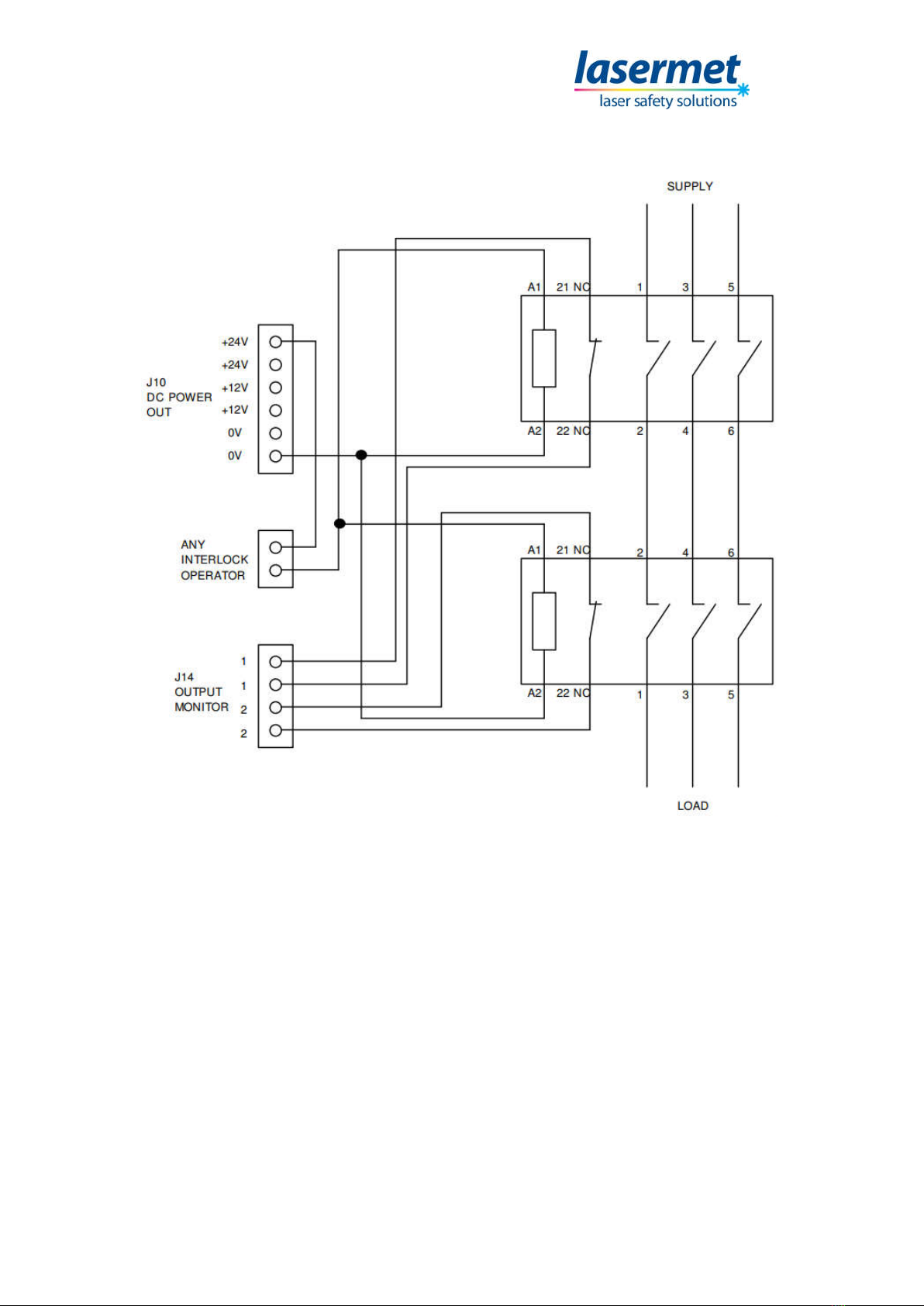
The box contains two contactors whose line contacts are pre-wired in series such that the power to
the load is cut if either or both contactors open. The ICS monitors both contactors and if one of them
fails to open when the system is disarmed, the ICS cannot be re-armed. This provides protection
against the ‘dangerous’ failure of a single contactor.
The contactor box needs to be wired to the line and load cables to be switched, and the box may
conveniently be located near these.
All wiring to the contactor main terminals must be made using wire of current and voltage rating
appropriate to the power to be carried.
Overcurrent protection devices must be provided on the supply side of the main contacts to protect
the load, contactors and wiring against excessive current under fault conditions.
The contactors are provided with four-line contacts. For a single-phase installation, use two of the
contacts only to switch live and neutral. For three-phase installation, use three contacts for the three
phase lines and the fourth for the neutral.
NOTE: Ensure that earth continuity is maintained at all times between line and load cables using
separate earth terminals. The earth must not be switched through the contactors.
It is then necessary to run either one 6-core or two 4-core cables between the ICS-5 / ICS-6 and the
contactor box. These cables will carry low current 24V control signals, and cables with 7/0.2mm
stranded copper cores are ideal. Lasermet can supply suitable miniature double-insulated cable with
a 250V insulation rating, which allows the cables to be run in proximity to 110V/240V mains cables if
needed.

ICS Contactors Wiring Manual
01518-53-000 Page 5 of 8 Issue 2 13 January 2020
The control wiring is shown below.
Lasermet provides a full range of laser interlock equipment including control systems, interlock
switches, illuminated warning signs, laser shutters, door locks, external power supplies etc. which
can be connected to provide a complete laser interlock system. Full support, design and installation
is available from Lasermet, please contact us for any queries. Contact details are given at the end of
this manual.

ICS Contactors Wiring Manual
01518-53-000 Page 6 of 8 Issue 2 13 January 2020
3 Testing
Testing should only be undertaken by a qualified electrical engineer.
A suitably rated tester is required to verify presence/absence of mains electrical power on the
contactor terminals and any socket outlets or load equipment connected to the contactor output.
During the tests hazardous voltages will be present inside the contactor box and on controlled outlet
sockets or load equipment. Use appropriately insulated test equipment and keep unauthorised
personnel clear of the test area.
During testing power will be fed to any connected equipment. Ensure that this will not present a
hazard.
Turn on the ICS power switch and confirm the ICS is powered (lights on front panel or power switch).
Set the ICS ready for arming, with all monitored doors closed. Set the ICS keyswitch to ‘Enable’. The
‘Arm’ button should be illuminated blue.
Turn on the mains supply to the contactor box and confirm that voltage is present on the input line
terminals of the contactors.
Verify that the contactors are not energised and that there is no voltage on the output (load)
terminals of the contactors, or on any outlet sockets or at the controlled device (e.g. laser) supply
input terminals.
Press the ‘Arm Laser’ button on the ICS and confirm the ‘Laser Armed’ indication is lit.
Verify that both contactors are energised and that the correct voltage is present on all controlled
socket outlets and/or load equipment supply terminals.
Disarm the ICS by opening a controlled door or set the keyswitch to ‘Disable’ and confirm that both
contactors are de-energised and there is no voltage on the controlled sockets or equipment.
Isolate the electrical supply to the contactor box. Remove the wire from terminal 21 of one of the
contactors. Set the ICS keyswitch to ‘Enable’, press the ‘Arm Laser’ button and confirm that the ICS
does not arm, the ‘Arm Laser’ button does not light, and the contactors are not energised.
Replace the wire to terminal 21 of the first contactor, remove the wire from terminal 21 of the other
contactor and repeat the test.
Refit the wire to terminal 21 of the second contactor. Repeat the test and confirm that the ICS does
arm, the ‘Laser Armed’ light is lit, and the contactors are energised.
Set the ICS keyswitch to ‘Disarm’ and turn off the ICS power switch. Fit the cover to the contactor
box and restore the supply to the contactor box.
Testing is complete.

ICS Contactors Wiring Manual
01518-53-000 Page 7 of 8 Issue 2 13 January 2020
4 Specifications
Safety Performance Up to PL’e’ to EN ISO 13849-1:2008
when wired as detailed in this instruction.
Supply Voltage 24VDC nominal.
Power Consumption 12W typical (32A contactors).
Output Contact Rating Refer to markings on contactor bodies.
Ingress Protection IP40
Operating Conditions 0° to 55°C, 0% - 95% relative humidity non-condensing.
Size 180mm wide X 182mm high X 163mm deep
Dimensions are approximate. Values given as ‘typical’ are average values measured across a number
of samples and are not guaranteed. Lasermet reserve the right to alter any specification without
prior notice.
5 Warranty
Lasermet provide a 12-month warranty for defects in materials and manufacture, from the date of
installation or delivery. Installations completed by Lasermet are covered against defects in
workmanship for 12 months.
Damage or defects caused by other factors are not covered. For example, industrial contamination,
incorrect cleaning, storm damage. Consequential loss is not covered under warranty. Compensation
for indirect or direct loss or damage is expressly excluded. Rectification of the defects or a
replacement does not initiate a new warranty period.
For all deliveries, payments and other legal transactions, English law takes precedence for any
litigation.

ICS Contactors Wiring Manual
01518-53-000 Page 8 of 8 Issue 2 13 January 2020
6 Contact Details
Lasermet provide a full range of laser interlock equipment including interlock switches, illuminated
warning signs, laser shutters, entry keypads with built-in fail-safe override timer, door locks, external
power supplies etc. which can be interconnected to provide a complete system. We also supply
equipment and consultancy covering all aspects of laser safety. Full support, design, and installation
is available from Lasermet, please contact us for any queries.
For sales and technical support:
Lasermet Ltd.
Lasermet House,
137 Hankinson Road,
Bournemouth
BH9 1HR
United Kingdom.
Tel: +44 (0) 1202 770740
Fax: +44 (0) 1202 770730
Website: www.lasermet.com
Lasermet Inc.
10N Martingale Road, Suite 400,
Schaumburg, Illinois 60173
United States.
Tel: 847 466 1475
Website: www.lasermet.com
Other manuals for ICS-6
1
This manual suits for next models
1
Table of contents
Other Lasermet Measuring Instrument manuals