Merrow 60AD User instructions
^WS
W^li
?!»%»
•
T 1
«t
*<
iM
rfwwif
SM^w^wM0,
'•*
1
l^l»S
IWHM[j|b^^^iifti
WfKnM
9
lsK<R£id»]
Sfw«.
mp«
•^>1
i*iE^-
From the library of: Superior Sewing Machine & Supply LLC

Instructions for Setting Up
and
Operating
THE
MERKOW
High
Speed
Trimming and Overseaming Machines
Class
60
The
Merrow
Machine
Company
28
Laurel
Street
Hartford,
Conn.,
U.
S. A.
Copyright
by
The
Merrow
Mnchine
Compnny,
1905. 1909. 1918, 1917, 1919, 1922. 1928. 1930, 1933, 1937, 1944
From the library of: Superior Sewing Machine & Supply LLC

THE
MERKOW
MACHINE
COMPANY
T
^HIS
comx)any
has
exclusive
control
of
numerous
inventions
for
which
Letters
Patent
liave
been
granted,
under
some
of
which
the
machines
indicated
in
this
book
have
been
made.
These
patents
also
include
many
products
and
methods.
All
machines
other
than
those
made
by
this
company
containing
any
one
or
more
of
the
features
covered
by
any
of
said
patents,
infringe
the
latter,
and
each
individual
maker
or user is liajjle for the profit obtained by the
use
of
the
patented
inventions
as
well
as
damages
siistained
by
the
owner
of
the
patents.
All
these
imu^hines
are
especially
designed
and
constructed
for
continuous
running
at
high
speed,
and
with
reasonable
care
they
are
always
used
witli
great
economy
in
cost
of
production
and
I'epairs.
- " 'v. ]
From the library of: Superior Sewing Machine & Supply LLC
.CLASS
60
INSTRUCTION
BOOK
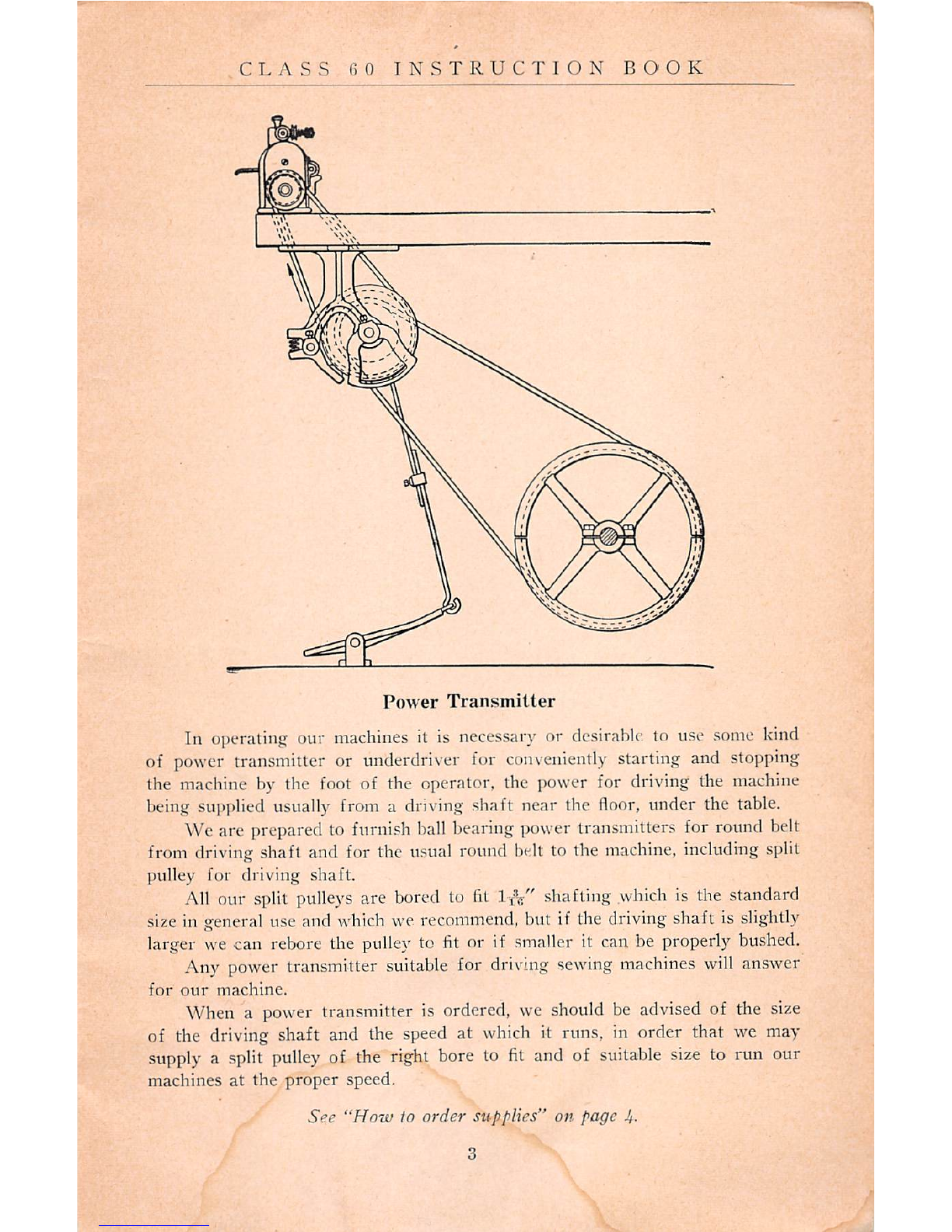
Power
Transmitter
In operating our
machines
it is
necessary
or
desirable
to use
some
kind
of
power
transmitter or
underdriver
for
conveniently
starting
and
stopping
the
machine
by the
foot
of the operator, the power for driving the
machine
being
sui>plied
usually from a driving shaft near the
floor,
under the
table.
We are prepared to
furni.'^h
ball
bearing
power
transmitters for
round
belt
from
driving
shaft and for the
usual
round
belt to the
machine,
including
split
pulley for driving shaft.
All
our
split
pulleys
are
bored
to
fit
!•£%"
shafting
which
is
the
standard
size
in
general
use
and
which
we
recommend,
but
if
the
driving
shaftis
slightly
larger
we
can
rebore
the
pulley
to
fit
or if
smaller
it
can
be
properly
bushed.
Any
power
transmitter
suitable
for
driving
sewing
machines
will
answer
for
our
machine.
When a
power
transmitter is
ordered,
we
should
be
advised
of the
size
of the driving shaft and the
speed
at which it runs, in order that we may
supply
a split
pulley
of the right bore to
fit
and of
suitable
size
to run our
machines at the proper speed.
See
"How
to
order
supplies" on page
Jf.
From the library of: Superior Sewing Machine & Supply LLC
THE
MERROW
MACHINE
COMPAN.Y
The ball bearing transmitters permit of setting the machine at or very
near the front edge of the table and are desirable for continuous running at
very
high
speeds.
The front end of the forward leg of the ball bearing power transmitter
should
be
set
under
the
table
about
one
and
one-half
inches
back
from
the
front edge of the base of the machine set on top of the table.
A convenient guide for boring the belt holes at the proper angles may be
made from a
short
piece of board four inches wide and seven-eighths of an
inch thick with either end sawed to the proper angle, which can be taken from
a
.sketch
made to scale in the manner indicated on page 3.
HOW
TO
ORDER
SUPPLIES
A Price List of Parts for the Merrow Class 60 Machines, alphabetically
and
numerically arranged with illustrations of
model.«:
of parts and code words
therefor, is available upon request.
Refer to illustrated parts and order by model number there given, stating
both serial
and
style number of the macliine for which the parts are wanted.
When
ordering needle plate, specify width of finish desired, whether long
or short chaining finger and size of needle used.
Loopers
may be
ordered
by model number, which is stamped on the
shank
of each looper; or otherwise, by stating whether upper or lower loopers and
whether for the one, two or the three-thread stitch, together with the style
or serial number of the machine in which they will be used.
We have a complete record of all parts of each machine as it leaves
our
factory and as all parts are strictly interchangeable we can supply duplicates
if given the name of the part with serial and style number of the machine.
Postage, registry, special delivery and insurance cost will be charged.
We
shall
take
every possible precaution to insure prompt
and
safe
delivery
but
cannot
be responsible
for
delays
or
losses in transit.
From the library of: Superior Sewing Machine & Supply LLC
This manual suits for next models
16
Other Merrow Sewing Machine manuals


