Merrow Class 70 User manual

INSTRUCTIONS
FOR
SETTING
UP
AND
OPERATING
CLASS
MERROW
MACHINES
r
INTRODUCTION
This
book
is
published
!or
the
guidance
of
those
persons
responsible
for
the
operation
and maintenance of
Merrow
Class
70
Butt-Seaming
Machines.
II
contains
diagrams
and
descriptive
information
concerning
the
most
common
adjustments
necessary
to
assure
maximum
production of
the
highest
quality.
For
individual
problems,
consult
your
nearest
Merrow
Distributor.
The
Merrow
Class
70
Machines
are
designed and
constructed
for
continuous and
per-
fect
operation
at
high
speed
.
The
utility
and
durability
of
Class
70
Machines
are
recog-
nized
features
or
their
design.
Automatic
lubrication,
light, Crcely moving
parts,
and
easily
adjusted
assemblies,
reduce
to a minimum
the
maintenance
required
to
obtain
superb
performance.
Class
70
Machines
overseam
and
trim
simultaneously
and
produce
either
a
one-
thread
or
two-thread
stitch
formation.
By
cutter
adjustments,
the
seam
configuration may
be a
true
butt
seam,
a
gap
seam
or
an
overlap
seam,
while
maintain
ing
the
thinness
necessary
for
a good
fabric
processing
joint.
We
also
make
other
classes
of
machines
including
Class
"MG"
Overstitching
Machines,
Plain
Crochet Machines,
and
Shell
Stitch
Crochet
Machines.
These
machines
are
being used
successfully by
manufacturers
throughout
the
world.
THE
MERROW
a
MACHINE
COMPANY
240
Day St., Newington,
CT
06111
Telephone {860) 666-0109
Fax (860) 666-TT30

From the library of Superior Sewing Machine & Supply LLC - www.supsew.com
THE
MERROW
MACHINE
COMPANY
____
____________
_
HOW
TO
ORDER
Send
parts
order to
your
nearest
Merrow Distributor
or
The
Merrow
Machine
Company,
Newington,
CT
06111, U.S.A.
When
ordering
replacement
parts,
include
the
Style
of
the
machine,
the
Name
of the
part
(see
diagrams
included), and the
letters
and
numbersstamped
on the
part.
(The
stamping
on
a
particular
part
is
insufficient
information
without giving
the
name
of
the
part.)
All
enameled
parts
will be
furnished
in
grey
.
If
difficulty
is
experienced
in
selecting
the
proper
part
number
desired,
we
expect
to
be
able
to
make
proper
selection
from
our
records
if
given
the following
information:
(
1)
The
Name
of
Part
(2)
The
Style
and
Serial
Number
of
Machine
(3)
Special
information
if included below:
(a) Needle Pl
ates
-
specify:
Machine
Style (70-D3B, 70-Y3B,
etc
.). Machine mounting,
(table,
railway,
rotary
stand,
and
the
manufacturer
of
such
mounting).
Type
of
seam
(butt,
gap,
overlap,
etc.),
size
of
needle
used,
(number
of
needle
plate
is
stamped
on
under-
side
of
plate).
(b)
Loopers
-
specify:
upper
or
lower,
one
or
two
thread
stitch.
(Number
of
looper
is
stamped
on
the
shank
near
the
butt
end.)
(c)
Parts
for
Feeding
Mechanism
-
specify:
front
or
rear
feed
if
machi
ne
has
differential
(gathering)
feed
.
When
ordering
replacement
parts
for
chemical
nickel
plated
machines
(styles
70-lD-2
CNP,
and
70-D3B
CNP) follow the
procedure
stated
above,
specifying
on
the
order,
parts
for
chemical
nickel
pl
ated
machine,
or
write
the
letter
"N"
after
the
part
number.
(Example,
Feed
Dog A-81-1!:'J
MERROW
MACHINES
ARI
DISTR
I
IUTID
IY
2
OTHER
MlRROW
MACHINES
• CLASS
MG
OVERSTITCHI
NG
MACHINES
• PLAIN CROCHET MACHINES
• BLANKET HEMMING MACHINES
•
SHELL
STITCH
CROCHET
MACHINES
Oesc,,p11ve
111erature
and
samples
of
st11ches
produced will be
prov1d&d
on request
From the library of Superior Sewing Machine & Supply LLC - www.supsew.com
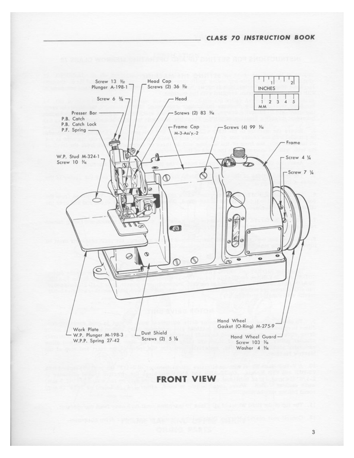
Screw 13
~
Plunger A-198-1
Screw 6
Presser
Bor
----
P.B.
Cotch
P.8. Cotch
loc
k
P.F
. Spring
W.P. Stud M-324-1
Screw 10 ¼
Work Plote
W.P. Plunger M-198-3
W,P.P. Spring 27-42
CLASS
70
INSTRUCTION
BOOK
Heod
Cop
Screws
12)
36
~
11
I
'11
I I I
21
I
INCHES
Heod I I I I I I
1 2 3 4 5
MM
Screws
121
83 ¼
rScrews
14)
99 ¼
Fromc
Oust Shield
Screws
121
5
'I,
FRONT
VIEW
..
Hond Wheel
Gasket
1O,Ring) M-275-9
Hand Wheel
Guard
Screw 103 ¼
Wosher 4 ½,
Screw 4 ¼
Screw 7 ¼
3

From the library of Superior Sewing Machine & Supply LLC - www.supsew.com
THE
MERROW
MACHINE
COMPANY
______________
_ _ _
INSTRUCTIONS
FOR
SETTING
UP
AND
OPERATING
MERROW
CLASS
70
SETTING THE
MACHINE
1.
Upon
removing
the
machine
from
its
box,
observe
its
threading
carefully
and
compare
ii
with
the
threading
diagram
supplied
with
the
machine.
2.
Keep
this
threading
diagram
for
further
reference.
The
matter
of
threading
is
very
important
and
if
difficulty
arises,
the
threading
of the
machine
should
be
compared
with the
individual
threading
diagram
supplied.
Threading
is
simple
but
must
be
accurate.
3.
Secure
the
machine
to
the
table
with the
screw
and
boll
provided.
This
assembly
should
be
parallel
with the
center
line
of
the
motor
and in
such
a
position
that
when the
machine
is
set
on
the
assembly,
the
front
of the
machine
will
be
three
or
four
inches
back
from
the
front
of
the
table
with
Its
hand
wheel
to
the
right
of
the
operator
.
4.
Assemb
le
thread
stand
and
screw
its
base
to
the
table
in
back
of
the
machine.
5.
The
thread
guides
at
the top of
the
thread
stand
should
be
directly
over
the
center
of the
cones
of
thread.
6.
The
thread
should
be wound on
cones
which
should
stand
vertically.
The
thread
from
the
cone
should
lead
to
the top of
the
thread
stand,
through
the
eye
on the
cross
rod
and
over
the
other
leg
of
the
U
shaped
cross
rod.
7. Be
sure
the
thread
will
come
off the
cones
readily
, with
uniform
tension
and
that
it
cannot
catch
under
the
cone
or
be
otherwise
retarded.
8.
Since
oil
has
been
drained
from
the
machines
before
shipping,
the
main
reservoir
must
be
filled
before
the
machine
is
used.
(Note
section
14.)
SPEEDS
The
Styles 70-D3B-2
and
70-Y3B-2
have
a recommended speed
of
2250
stitches
per
minute.
Styles
70-O3B
and
70-Y3B are designed to
run
at
1500-1800
stitches
per
minute, Merrow Styles 70-ABB,
70-AON-l
and
70-ABBY
are
designed to
run
2800-3000
stitches
per
minute.
Style
70-1D-2isdesigned
to
run
4000
stitches
per
minute. While
these
machines
may
run
well
with
littlecare,
they
will
give
better
results with
suitable
attention.
MOTOR
DRIVE
UNIT
9.
To
obtain
full
efficiency,
the
motor
drive
equipment
must
be
kept
in
good
operating
con-
dition
in
order
to
start
and
stop
the
machine
with
minimum
delay.
When
laying
out
the
motor
drive
equipment,
attempt
should
be
made
to
avoid
driving
from
a
large
pulley
to
a
re
l
atively
smaller
pulley, the
centers
of
which
are
close
together,
as
such
an
arrangement
will
allow
excessive
slippage
of the
belts,
materially
reducing
the
speed
of
the
start
and
stop
of
the
Merrow
Machine.
10. A
V-Belt
Hand
Wheel with an
effective
{pitch)
diameter
of
3-1/3"
{85
mm)
is
supplied
with
70-O3B
and
Y3B Models. On 70-ABB
and
ABBY
machines
the
effective
(pitch)
diameter
is
2-1/8"
(54
mm)
. If
an
individual
motor
is
used,
the
machine
may
be
run
with a
3/8"
(9. 5 mm)
width
endless
V-Belt.
Where
round
belting
is
used,
either
1/4"
(6. 5 mm)
or
5/16"
(8 mm)
round
belting
may
be
used.
11. The top of the Hand Wheel
of
all
Class
70
machines
must
tu
r n away
from
the
operator
.
12.
Consult
your
nearest
Merrow
Distr
ib
utor
to
assure
proper
motor
dr
ive
equipment.
4

From the library of Superior Sewing Machine & Supply LLC - www.supsew.com
CLASS
70
INSTRUCTION
BOOK
LUBRICATION
13. GENERAL:
In
the
lubricati
on of the
machine
the
oil
is
metered,
feeding
oil
in
proper
amounts
to
all
bearing
surfaces.
It
is
a one-way oiling action and when the
reservoir
supply
is
used,
the machine
must
be
refilled.
The
reservoir
holds enough
for
forty
hours
of
seaming
.
14. Oil is
fill
ed through a hole
under
the
Cap
Screw
of the Oil
Filler
Assembly
into
the
main
reservoir.
About
8
ounces
(0. 250
litres)
of
a high
grade
turbine
oil
of
about
150 Sayboldt
seconds
at
100°
Fahrenheit
(37. 5°C) is
recommended.
To
drain
the
oil,
dismount
the
machine
and extend
the
feed
mechanism
end
of
the
machine
over
the
end of the table.
After
providing a
means
of
catching
the
oil,
unscrew
the
Oil
Drain
Screw
11-3/ 8 (located
at
the
rear
of
the
machine in the base)
several
turns.
F C. Oil
Tub
e
M-95-,
Au
•y.•A
Upper Shafi
A5:1,y
Goskc1
CO
-Ri
ng)
M275-11 "
~
Oil
Meter-...___
'
,.;:)
"=!J
M 35
0,(
A
lo
El
~
~
F.C
Oa
M••••
Ho
l
dc,
(i
~
Screw 6 ~
-----..
.z I
I
Scr
ow
!i
½r
---...._.
:
= I
,,
I
_,,--:
t
, I
I
I
I
I
r t
I
~
~
,,. Oil
Flhe,/
M,
332
,2
,I
Pump
Pl1,1nger
M,198,2
O.P,
P.
Spring
27
,
.CO
O,P
.P Screw Godcet
M-275-5
0 .
P,P
,
Sc1ow
8
¾.
Oil
Meter M-350
..(
Ato El
~
Gosket
(O-R
i
ngl
-M-275•
11
U.S. O
il
Me,e,
Holder
M,137,5
Goskel (O,Ring)
M,275-17
Filler
Any
. M-329-Au'y,-1
Uppor
Shoft Oil Collecto, M,137,3
I
I I I II I
ltiCHES I I
2 3
MM
I
A I
s
FRAME CAP
AND
UPPER SHAFT
OILING
PARTS 5
From the library of Superior Sewing Machine & Supply LLC - www.supsew.com
THE
MERROW
MACHINE
COMPANY
________________
_
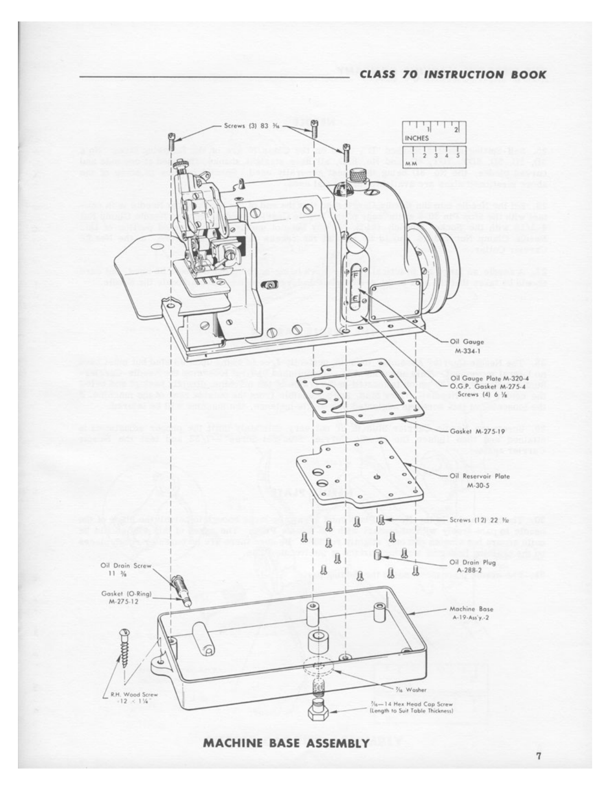
15.
The
oil
coming
up
from
the
reservoir
is
filtered
by a
bronze
screw-type
filter
located
in
the
frame
above
the
Oil
Reservoir
Plate.
16.
The
Upper Shaft
Pump
provides
a continuous
oil
flow
to
assure
proper
lubrication
without
the
use
of
wicks.
The
Pump
is
operated
from
an
eccentric
groove
in
the
main
Upper
Shafi.
The
Upper Shafi
Pump
draws
oil
from
the
main
reservoir
and
forces
ii through
the
Oil
Bubbler
Pipe
to
the
Oil
Bubbler
Pipe
Cap.
Some
oil
is
bypassed
from
the
Oil
Bubbler
Pipe
to
the
F. C.
Oil
Meter
Holder
and
to
the
Upper
Shaft
Oil
Meter
Holder.
17. FRAME CAP LUBRICATION:
F.C
.
Oil
Feeder
Tube
supplies
oil
to
the
upper
and
lower
looper
carrier
assemblies
and
the
cam
roll
bearings.
The
oil
flows
to
the
F.C.
Oil
Feeder
Tube
through
an
oil
meter
which
is
enclosed
in
the
F.
C.
Oil
Meter
Holder.
The
F . C.
Oil
Meter
Holder
is
located
in
the
frame
beside
the U.S.
Oil
Pump
Screw.
18.
UPPER
SHAFT LUBRICATION:
The
oil
bypassed
through
the
Oil
Bubbler
Pipe
fills
up the
Upper
Shafi
Oil
Meter
Holder
cavity
and
a
limited
amount
flows
through
an
oil
meter
in
the
Holder.
The
oil
drops
into
the
Upper
Shaft
Oil
Collector
and
is
fed
past
the
Oil
Distributor
Rod
located
in
the
Upper
Shaft.
This
action
distributes
the
oil
to
the
bearing
surfaces
of
the
main
shafts
on
the
left
end
of
the
machine,
the
Needle
Carrier
Assembly,
the
Upper
Cutter
Carrier
Assembly,
and
the
Feed
Mechanism.
19. Some of
the
oil
not fed into the
Oil
Bubbler
Pipe
is
forced
along
the
outside
of the
Upper
Shaft,
to
the
face
of the
Upper
Cam
Boss
.
20. LOWER SHAFT LUBRICATION:
The
Lower
Shaft
is
lubricated
by
oil
flowing into
the
Lower
Shaft
Oil
Meter
Holder
through
an
oil
meter
to
the
Lower
Shaft.
This
Meter
Holder
is
located
in the
frame
between
the
right
Upper
and
Lower
Shaft
Holes.
(Note Section 73,
line
i.)
Oil
METERS
21.
There
are
four
grades
available
for
various
rates
of
oil
flow.
22.
Oil
Meters
in
the
machine
are
selected
at
the
factory
to
provide
proper
lubrication
for
normal
machine
uses.
23. If
the
machine
is
to
be
used
in
wet
locations
or
wet
cloth
is
to
be
sewn,
then
the
F.
C.
Oil
Meter
and
U.S.
Oil
Meter
should
be
changed
to
grade
"A"
(coarse)
.
24.
The
following
precautions
are
recommended:
6
a.
Never
allow
the
oil
level
to
go
below
the
empty
"E"
line
on
the
Oil
Gage.
b.
Occasionally
clean
the
lint
around
the
Feed
Dogs
and
from
behind
the Dust
Shield
(do
not
use
compressed
air}
.
c .
Clean
screen
on
the
Oil
Filler
Assembly
if
filling
the
machine
becomes
difficult.
1.
To
clean
the
screen,
unscrew
this
assembly
from
the
machine
and
clean
with
compressed
air
or
a
solvent.
d.
The
Inlet
Oil
Filter
is
located
inside
the
main
reservoir.
This
may
be
replaced
by
removing
the
Oil
Reservoir
Plate
and
unscrewing
the
filter.
It
may
be
cleaned
by
soaking
in
solvent
and
blowing
through
ii
with
compressed
air
from
the
inside
out.
From the library of Superior Sewing Machine & Supply LLC - www.supsew.com
CLASS
70
INSTRUCTION
8OOK
~Sc,ew,
131
83
II.~
I
I
(S) I
I
MACHINE
BASE
ASSEMBLY
0
0
1
1 J I II J I
2!
I
INCHE;
.
11 I I I I
M~
1 J 4 S
Oil
Gouge
M·33.t 1
Oil Gouge, Plate M-
320
4
0 .G P
Goi\e1
M ?75.
.,t
Screw, (4) 6 ¼
Oil
Retervo
ir Pfolc
M-30-S
7
From the library of Superior Sewing Machine & Supply LLC - www.supsew.com
THE
MERROW
MACHINE
COMPANY
________________
_
NEED
LE
25. Self-Setting
needles
marked
"D",
used
on
the
Class
70
are
of
the
following
sizes:
No's
3D,
4D, 5D, 6DT, 7DT, 8D, and No. 8SD,
all
have
straight
shanks,
flattened
at
one
side
and
curved
blades,
the
No.
3D
being
lhe
finest
generally
used.
Special
needles
in
some
of
the
above mentioned
sizes
are
available
for
special
uses.
26. Set
the
Needle into
the
Needle
Carrier
so
that
the
end
of
the
shank
of the Needle
is
in
con-
tact
with
the
Stop
Pin
36-6
at
the
rear
of
the
Needle
Carrier,
and tighten
the
Needle
Clamp
Nut
4-3/16
with
the
Socket Wrench
(44-2),
firmly
but
not
unduly.
The
beveled
portion
of
this
Needle
Clamp
Nut
4-3/16
should be
against
the
recess
provided,
therefore,
in
the
Needle
Carrier
Collar.
27. A
needle
as
large
as
practical
for
the
work
being
accomplished
should
be
used,
but
care
should
be
taken
that
the
slot
in
the
needle
plate
is
large
enough
to
accommodate
the
needle.
THE NEEDLE CARRIER
28.
The
Needle
Carrier
Assembly
must
be
perfectly
free
lo
swing upon
its
stud
but
must
have
no
latera
l movement.
This
adjustment
is
accomplished
by
first
loosening
the
Needl
e-Carrier-
Stud-Set-
Screw
8-7/32
which
is
located
in
the
frame
of
the
machine,
directly
back
of and below
the
center
of
the
Needle
Carrier
Stud, and
accessible
from
the
outside
rear
of
the
machine
. If
the
loosening of
this
screw
is
neglected
in
a
single
instance,
the
machine
will
be
injured.
29.
Screw
the
Needle
Carrier
Stud in
or
out
very
delicately
until
the
proper
adjustment
is
attained and
then
tighten
the
Needle-Carrier
Stud-
Set-Screw
8-7
/32 and
test
the
Needle
Carrier
again.
NEEDLE PLATE
30.
The
needle
slot
in the
Needle
Pl
ate
must
always
be
large
enough
to
permit
the
blade
of
the
n
eedle
to
pass
freely
without
contact
with
the
Needle
Plate
.
The
edges
of
this
slot
should
be
quite
square
but
smooth
and
only
slightly
rounded.
Be
sure
there
are
no
burrs
or
rough pl
aces
on
the
chaining
finger
or
working
surface
of the Needle
Plate.
31. The
needle
plate
must
match
the
feeding
parts.
8
From the library of Superior Sewing Machine & Supply LLC - www.supsew.com
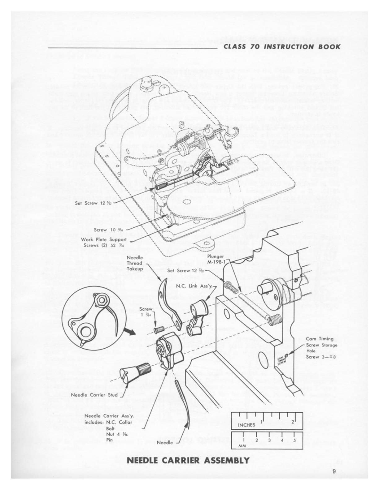
Wor
k Plote
Support
Screws
t2)
52
¾6
Needle
Thread
'\.
Ta
keup
'\.
Set Screw 12
½l
N.C. link Ass
'y
,
Screw j
--
1
~
1 -- -
t
--
- -
--
.
--
-
--
--
Need
le
Cor,icr
Stud
~
Needle
Conier
A.ss'y,
includes: N.C.
Collar
Bolt
N
ut
4 ¼
Pin
•..•
CLASS
70
INSTRUCTION
BOOK
.
--·
Com Timing
Screw
St0toge
\J
Hole
..
;1
Screw
3-#8
lii''
' ' '
I I
,I
'2'
I
NC
H
ES
I I I
2 3 4 5
MM
NEEDLE
CARRIER ASSEMBLY 9
From the library of Superior Sewing Machine & Supply LLC - www.supsew.com
THE
MERROW
MACHINE
COMPANY
________________
_
LOO
P
ER
S
ETTING
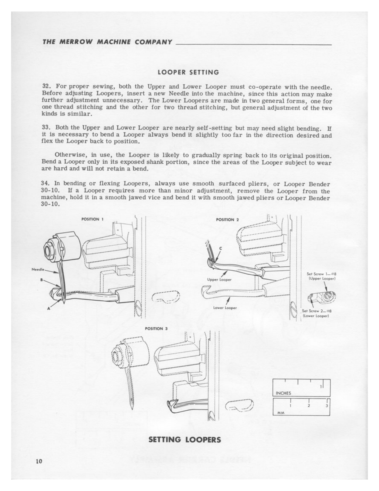
32.
For
proper
sewing, both
the
Upper and Lower
Looper
must
co-operate
with
the
needle.
Before adjusting
Loopers,
insert
a new Needle into
the
machine,
since
this
action
may make
further
adjustment
unnecessary.
The
Lower
Loopers
are
made in two
general
forms,
one
for
one
thread
stitching
and the
other
for
two
thread
stitching,
but
genera
l
adjustment
of the two
kinds
is
similar.
33. Both
the
Upper and Lower
Looper
are
nearly
self-setting
but may need
slight
bending. If
it
is
necessary
to
bend a Looper always bend
it
slightly
too
far
in
the
direction
desired
and
flex
the
Looper
back
to
position.
Otherwise,
in
use,
the
Looper
is likely
to
gradually
spring
back
to
its
original
position.
Bend a Looper only in
its
exposed
shank
portion,
since
the
areas
of
the
Looper
subject
to
wear
are
hard
and
will
not
retain
a bend.
34.
In
bending
or
ilexing
Loopers,
always
use
smooth
surfaced
pliers,
or
Looper
Bender
30-10. If a Looper
requires
more
than
minor
adjustment,
remove
the Looper
from
the
machine, hold it in a
smooth
jawed
vice
and bend it with
smooth
jawed
pliers
or
Looper
Bender
30-10.
I
IN
C~ES
,I
I
r-A
I I
~
-
/·
1 i
'
~
..
:··:
.
./
MM
SETTING LOOPERS
10

From the library of Superior Sewing Machine & Supply LLC - www.supsew.com
CLASS
70
INSTRUCTION
SOOK
35.
Steps
to
Setting
Loopers:
a.
Swing the
Presser
Foot
Assembly
out or
position
and
remove
the
Needle
Plate,
Lower
Looper
Thread
Tube,
Feed
Dogs,
and
Dust Shield
for
accessibility.
Remove both
Loopers
by
means
of
the
Set
Screws
provided.
b.
The
Lower Looper
is
best
set
and
adjusted
before
the
Upper
Looper
is
placed
in
the
machine
and
after
the
Needle
has
been
properly
set
in.
1.
First
loosen
the
Lower
Looper
Screw
which
is
accessible
through
the
hole
in
the
front
of
the
Frame
Cap. As
this
Screw
is
just
to
the
left
of
the
Upper
Looper
Screw,
be
sure
to
loosen
the
proper
screw.
36.
Insert
the
Lower
Looper
pushing
it
in
as
far
as
it will go, and
tighten
the
Set
Screw
against
the
flat
of
the
Looper.
37. Slowly
turn
the
Hand Wheel away
from
the
operator.
The
Needle on
its
downward
stroke
should gently
contact
the
shank
of
the
Lower
Looper
at
point
"A"
. When
properly
set,
the
point
or
the
Lower Looper
must
make
gentle
but
firm
contact
with
the
Needle
at
point
"B",
but
should not deflect
the
Needle. If
necessary,
bend
the
Looper.
38.
The
Upper
Looper
is
secured
to
the Upper
Looper
Carrier
by a
Screw
accessible
through
the
right
hand
end
of
the opening through
the
front
of
the
Frame
Cap
.
Insert
the Upper
Looper,
pushing
it
into
the
Upper
Looper
Carrier
as
far
as
it
will go, and tighten
the
Set
Screw
against
the
flat
on
the
Upper
Looper.
39. Slowly
turn
the Hand Wheel away
from
the
operator.
The
Upper
Looper
should not
strike
the Needle but
the
point of Needle
should
pass
close
to
the
back
side
of
the
Upper
Looper
at
point
"C"
.
To
effect
this
adjustment
the
Looper
can
be
sprung
up
or
down,
as
well
as
sidewise.
40.
Turn
the
Hand Wheel
until
the
throat
of
the
Upper
Looper
is
about
to
pass
the
left
end
of
the Lower
Looper
on
the
upstroke.
When
properly
adjusted,
the
throat
of
the
Upper
Looper
should
pass
just
clear
of
the
left
end
of
the
Lower
Looper
on
the
up and down
stroke
as
shown
in
illustration
position
#3.
41.
Finally,
turn
the Hand Wheel
completely
around
and
see
that
the
Loopers
and
Needle
are
properly
adjusted
to
each
other.
After
adjustment,
check
to
be
sure
the
Set
Screw
holding
each
Looper
is
properly
tightened.
THREADING
42.
To
thread
the
machine,
follow the
Threading
Diagram
provided
with
each
machine.
A
duplicate
may be obtained upon
request
provided
that
the
style
and
serial
number
of
the
ma-
chine
is included with
the
request.
The
matter
of
threading
is
important
and although
simple,
it
must
be
accurate.
43. When
threading
the
Looper
Threads,
it will
be
found convenient
to
use
a
threading
wire.
With
the
thread
or
yarn
inserted
in
the
eye
of
the
threading
wire,
pass
the
wire
through
the
thread
eyes
and
tension
discs
as
shown on
the
threading
diagram
.
To
place
the
Lower
Looper
in position
to
be
threaded,
turn
the
Hand Wheel
until
the Needle
is
in
its
highest
position.
Then, it
will
be
possible
to
pass
the
threading
wire
through both the
L.
L.
Thread
Tube
and
the
Lower
Looper
simultaneously.
44.
The
machine
is
ready
to
"chain"
after
threading
the
needle
or
needle
and
looper
as
shown
on
the
threading
diagram.
45.
It
is
generally
advisable
to
keep
tension
on
the
thread
as
light
as
necessary
to
produce
good
results.
11
From the library of Superior Sewing Machine & Supply LLC - www.supsew.com
THE
MERROW
MACHINE
COMPANY
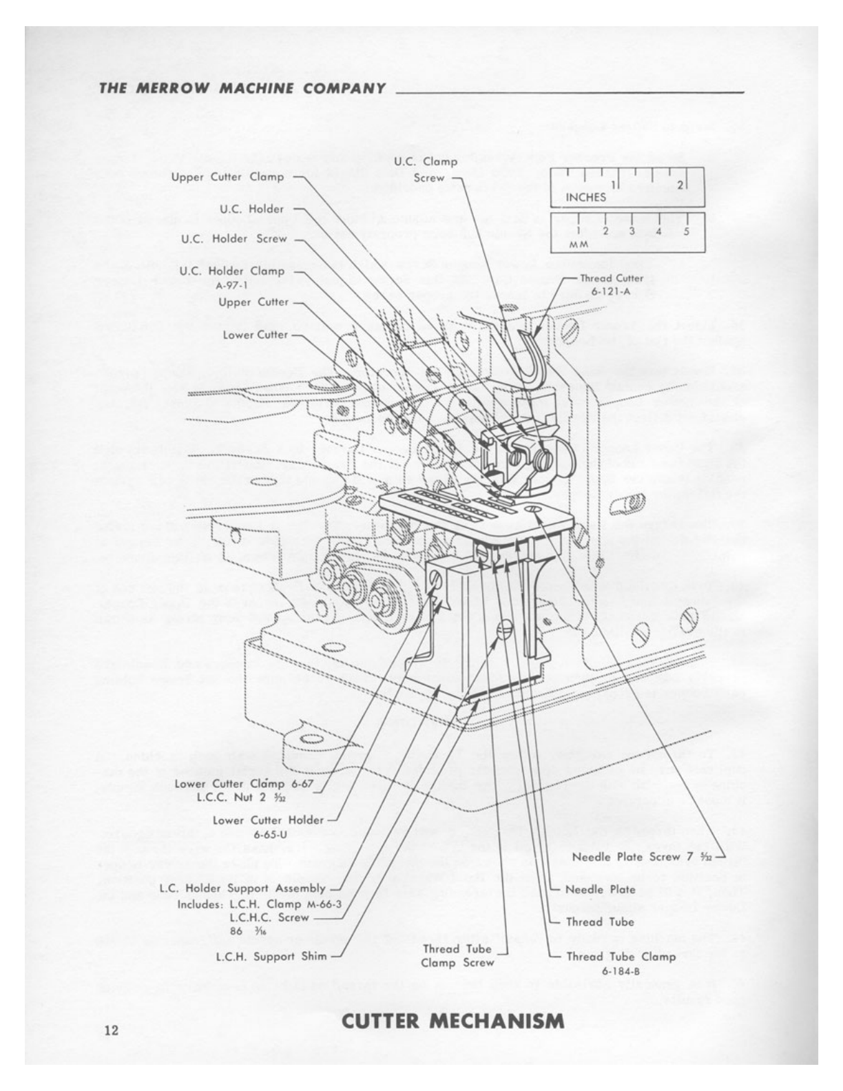
Upper
Cutter
u.c.
Holder
Clamp~
U.C.
Holder Screw
U.C.
Holder Clomp
A-97-1
Upper Cutter
lower
Cutter Holder
6-6S-U
l.C. Holder Support Assembly
Includes, L.C.H. Clomp M-66,3
l.C.H.C. Screw
86
¼i,
l.C.H. Supporl Shim
U.C.
Clomp
INCHES
I I
2 3
MM
Threod Culler
6·121-A
.........
e·,·"
\
::----
·
f
i
i
:
:
~
..
j._.
;'/q
\,/
!
I
s
..
)~
~
~-
:
..
:;::::;:~::=-::::;:;.
--..:1..
....
:,.
~-~
~
:::
.:·1>~
;#'··
Thread Tube
Clomp
Screw
---~
Needle
Plate Screw 7
¾,
Needle
Plate
Thread Tube
Thread Tube Clomp
6,184-8
12
CUTTER
MECHANISM

From the library of Superior Sewing Machine & Supply LLC - www.supsew.com
CLASS
70
INSTRUCTION
BOOK
UPPER
AND
LOWER
CUTTER
46. GENERAL:
The
upper
and
lower
cutter
may be
adjusted
up and down
and
laterally
to
the
right
or
left.
47.
The
position of
cutters
determines
the
width of
the
fabric
within
the
seam
. When a
butt
seam
is
desired,
the cutting
surfaces
should
be
positioned
approximately
in
the middle
of
the
Needle
Flate
Chaining
Finger.
When a gap
seam
is
desired,
the
cutting
surfaces
shouldbe
positioned
as
for
a
butt
then
moved
to
the
left
about
1/2
the width of
the
gap
required.
Lap
seams
are
created
by
setting
the
cutting
surfaces
to
the
right
of
the
butt
seam
posit
ion.
The
position of the
cutters
will
vary
with
the
thickness
of
fabric
and
some
trial
settings
should be
made
to
determine
the
correct
position
for
each
weight
of
material.
Loosely
woven
materials
require
a
wider
setting
than light
fabrics.
48.
The
L.
C.
Holder
slides
in the L. C.
Holder
Support
Assembly
providing
lateral
movement
to
the
Lower
Cutter
. Do not allow the
Lower
Cutter
to
push too tightly
against
the
Upper
Cutter.
If
more
than a light
pressure
is
required,
it
usually
indicates
that
the
cutters
are
dull
and
should
be
sharpened.
ADJUSTMENT
49. Set
the
cutting
edge
of
the
Lower
Cutter
slightly
above the
upper
surface
of
the
Needle
Plate
by
means
of
the
L. C. C. Nut
2-5
/32.
Do
not
set
this
cutter
high enough
to
contact
the
lower
surface
of
the
Presser
Foot.
50.
Clamp
the L.
C.
Holder
to
the
width of
trimming
desired
by
Screw
86-3/16.
Turn
the
machine
over
by hand and
set
the
Upper
Cutter
so
that
in
its
lowest
position
its
cutting
edge
is
a
little
below
the
top
edge
of
the
Lower
Cutter.
This
adjustment
is
made
by
U. C.
Clamp
Screw
and
U.C.
Holder
Screw.
51. Loosen L. C. H.
C.
Screw
86-3
/
16
and
turn
the Machine
over
by hand.
The
downward
pro-
jection
at
the
rear
of
the Upper
Cutter
should
be in
contact
with
the
lower
Cutter
at
all
times.
52.
Press
the
L,
C.
Holder lightly
to
hold
the
cutters
together
and tighten the
L.
C.H.
C.
Screw
86-3/16
.
SHARPENING
THE
CUTTER
S
53.
The
Upper
and
Lower
Cutters
must
be
sharpened
in a
Cutter
Grinder, which
has
a
Jig
to hold
the
cutters
at
the
proper angle.
Those
customers who do
not
have
a Merrow
Cutter
Grinder
can
have
dull cutters
sharpened
by
sending
them to your distributor
or
to
the
Merrow Machine Company,
Newington, Connecticut 06111.
54. When using
the
Merrow
Cutter
Grinder,
be
sure
that
the
retaining
groove
for
the
cutter
is
perfectly
clean
before
inserting
the
cutter
and
clamping
the
cutter
into
the
cutter
holder.
The
cutter
should
be
carried
entirely
across
the
grinding
face
of
the
wheel,
to
prevent
the
wheel
from
becoming
worn
unevenly and
requiring
replacement
so
that
cutters
may
be
sharpened
properly.
55. Very
little
need
be
ground
off
the
cutters
. If
too
much is
ground
at
one
passage
across
the
face
of
the
wheel,
the
temper
of
the
cutter
will
be
drawn
and
its
cutting quality
greatly
im-
paired.
56.
The
cutter
should
not
be
discolored
by
grinding.
13
From the library of Superior Sewing Machine & Supply LLC - www.supsew.com
THE
MERROW
MACHINE
COMPANY
________________
_
FEEDING
MECHANISM
57.
Feed
Dogs
are
provided
with
either
fine
cut
teeth
or
coarse
cut teeth, single row
or
double
row, dependent upon
the
work.
Generally
the
feed
dogs
should
be
set
as
low
as
practical.
58.
The
length of
feed
can be changed
by
removing
the
Feed
Eccentric
and
substituting
another
Feed
Eccentric
of
different
throw.
Feed
Eccentrics
are
marked
to
indicate
approximately
the
number
of
stitches
per
inch
produced
at
the
edge
of
the
fabric.
59.
Feed
Dogs and Needle
Plates
must
match
each
other.
60.
The
letter
"D" in
the
Style
70-D3B
or
70-ABBD
means
it
contains
a
differential
or
gathering
feed.
The
differential
contains two
separate
Feed
Dogs with
their
separate
Feed
Carriers
and
separate
Feed
Eccentrics.
When it
is
desired
to
prevent
the
edge of
the
fabric
from
being
stretched
or
lengthened while
seaming,
the
Front
Feed
Dog is made
to
travel
a
greater
distance
than the
Rear
Feed
Dog. In
most
cases,
a
slight
difference
is
sufficient
and
the
number
of
each
Feed
Eccentric
and
the
difference
between
the
two
is
dependent upon
the
number
of
stitches
required
per
inch and
th
e
elasticity
of
the
fabric
itself.
61. On
certain
fabrics
it
may
be
desirable
to
tilt
the
Feed
Mechanism
. To
make
this
adjust-
ment,
loosen
the
Set
Screw
48-5
/32, slowly
turn
the
F.C.
Block
Pin
to
the
desired
location
and tighten
this
Set
Screw.
When
the
screw
slot
in
the
pin
is
level
with
the
base
of
the
machine,
the
Feed
Dog
will
be
in
their
standard
level
position.
It
is
never
necessary
to
remove
the Stop
Screw
48-5
/32.
This
leveling
device
on the feed
mechanism
permits
delicate
adjustment
of
feed
dogs
.
14

From the library of Superior Sewing Machine & Supply LLC - www.supsew.com
CLASS
70
INSTRUCTION
BOOK
f("t-d
Conif'r
Spoc~r
6-313A
Feed
Come,
(R)
M-74-3
foodO~(RI\
~1--@iP--
',
NUT
-
2¾.
-----
-
~
--
f C l Bu\hing
UH
--
~-
--
M-79-J
-
f~cd
f«c-nlt,c
ffl
NUJ
7"'
\
feed
f«fflJ,o(
(RJ
M.'76
'1
l
Feed
Comer
l,...~
!RI
M-76-1
Sc.rcw
II
I>,
FEED
MECHANISM
(DIFFERENTIAL)
FCt.8otttn
6•77•A
feed
Dog
if)
I I I
INCHES
I
7
MM
,I
lowu
Shoh
I
,I
I
I I I I
l • 5
15
From the library of Superior Sewing Machine & Supply LLC - www.supsew.com
THE
MERROW
MACHINE
COMPANY
"Y"
TYPE
FEED
MECHANISM
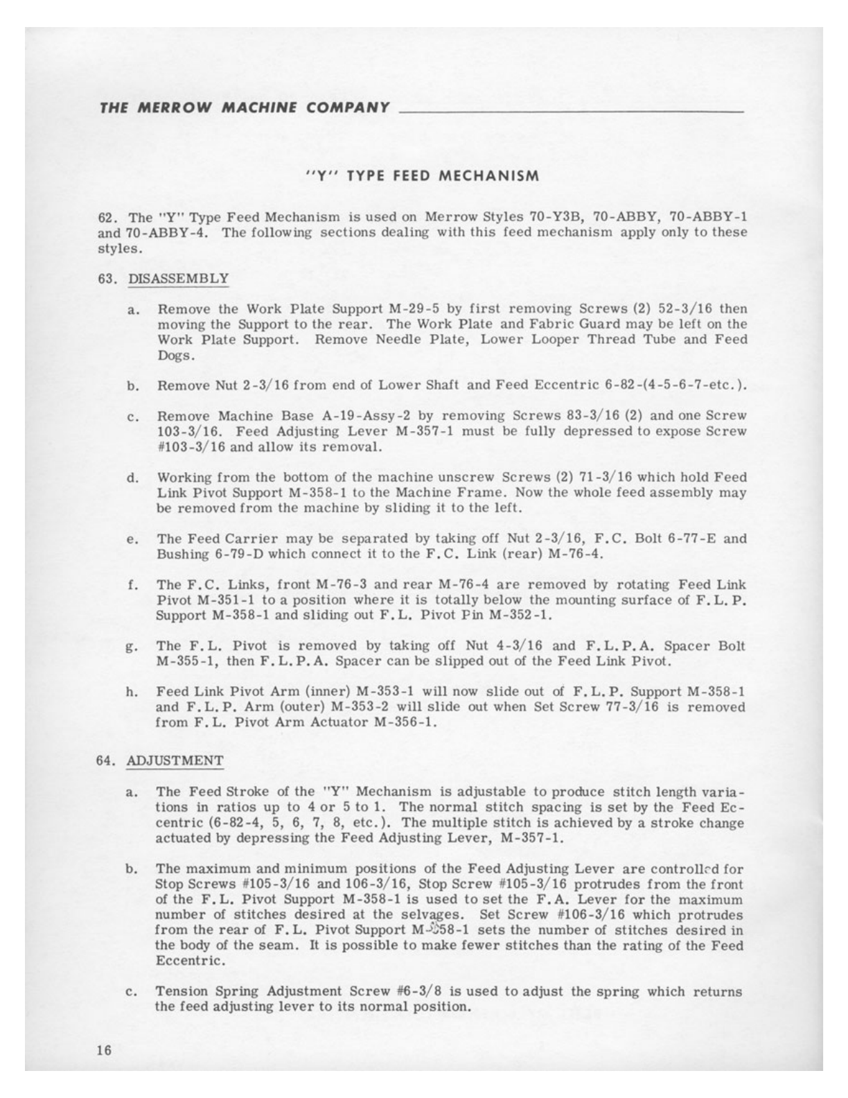
62
.
The
"Y"
Type
Feed
Mechanism
is
used
on
Merrow
Styles
70-Y3B, 70-ABBY, 70-ABBY-1
and 70-ABBY-4. The following
sections
dealing
with
this
feed
mechanism
apply
only
to
these
styles.
63. DISASSEMBLY
a.
Remove the Work
Plate
Support
M-29
-5
by f
ir
st
removing
Screws
(2) 52
-3
/16
then
moving
the
Support
to
the
rear.
The
Work
Plate
and
Fabric
Guard
may
be
lefl
on the
Work Pl
ate
Support.
Remove
Needle
Plate,
Lower
Looper
Thread
Tube
and
Feed
Dogs.
b. Remove Nut
2-3
/16
from
end
of
Lower
Shaft
and
Feed
Eccentric
6-82-(4-5
-6-
7-etc.).
c.
Remove
Ma
ch
in
e
Base
A-19-Assy-2
by
removing
Screws
83-3
/
16
(2)
and
one
Screw
103-3/16.
Feed
Adjusting
Lever
M-357-1
must
be
fully
depressed
to
expose
Screw
11103-3/16
and
allow
its
removal.
d. Working
from
the bottom of
the
machine
unscrew
Screws
(2)
71-3
/16 which hold
Feed
Link Pivot
Support
M-358-1
to
the
Machine
Frame.
Now
the
whole
feed
assembly
may
be
removed
from
the
machine
by
sliding
it
to
the
l
eft.
e.
The
Feed
Carrier
may
be
separated
by
taking off Nut
2-3
/16,
F.C.
Bolt
6-77-E
and
Bushing
6-79-D
which
connect
it
to
the F .C. Link
(rear)
M-76-4
.
f.
The
F. C. Links,
front
M-76-3
and
rear
M-76-4
are
removed
by
rotating
Feed
Link
Pivot
M-351-1
to
a
position
where
it
is
totally
below
the
mounting
surface
of
F.
L.
P.
Support M
-358-1
and
sliding
out
F . L.
Pivot
Pin
M-352-1.
g.
The
F.
L. Pivot
is
removed
by taking off Nut
4-3
/
16
and
F.
L.
P.A.
Spacer
Bolt
M-355-1,
then
F . L. P. A.
Spacer
can
be
slipped
out of the
Feed
Link
Pivot.
h.
Feed
Link Pivot
Arm
(inner)
M-353-1
will now
slide
out
of
F.
L.
P.
Support
M-358-1
and
F.
L.
P.
Arm
(outer)
M-353-2
will
slide
out
when Set
Screw
77-3
/16
is
removed
from
F.
L.
Pivot
Arm
Actuator
M-356-1.
64. ADJUSTMENT
16
a.
The
Feed
Stroke
of the
"Y"
Mechanism
is
adjustab
le
to
produce
stitch
length
varia-
tions
in
ratios
up
to
4
or
5
to
1.
The
normal
stitch
spacing
is
set
by
the
Feed
Ec-
centric
(6-82-4,
5,
6,
7,
8,
etc.)
.
The
multiple
stitch
is
achieved
by a
stroke
change
actuated
by
depressing
the
Feed
Adjusting
Lever,
M-357-1.
b.
The
maximum
and
minimum
positions
of
the
Feed
Adjusting
Lever
are
cont
r
oll:--d
for
Stop
Screws
1110
5-3
/16
and
106-3/16,
Stop
Screw
11
105-3
/16
protrudes
from
the
front
of the F .
L.
Pivot
Support
M-358-1
is
used
to
set
the
F.
A.
Lever
for
the maximum
number
of
stitches
desired
at
the
se
l
vages
.
Set
Screw
11106-
3
/16
which
protrudes
from
the
rear
of F .
L.
Pivot
Support
M->j58-l
sets
the
number
of
stitches
desired
in
the
body of the
seam.
It
is
possible
to
make
fewer
stitches
than
the
rating
of
the
Feed
Eccentric.
c.
Tension
Spring
Adjustment
Screw
116-3/8 IS
used
to
adjust
the
spring
which
returns
the
feed
adjusting
lever
to
its
norma
l
position.

From the library of Superior Sewing Machine & Supply LLC - www.supsew.com
CLASS
70
INSTRUCTION
BOOK
>
.,
~··
1
,~
'':
f/;
lo)
~ ·
.
.,_
f
••
Hd
~•;;;'
:pqw
•:•
.. ..
I'I I
,I
I
NCHES
" Y"
FEED
MECHANISM
17

From the library of Superior Sewing Machine & Supply LLC - www.supsew.com
THE
MERROW
MACHINE
COMPANY
Preuer
Foot
Sc,~
....
18
v.
Prcncr Fool
Ar,u
Screw 102
~
PRESSER
FOOT
ASSEMBLY I I I
INCHES
PF
. Fi
nger
Screw 8
Y•
I I
2 3
P.F. Brockel
A
,316•3
I
s
PRESSER
FOOT
AND
PRESSER
FOOT
FINGER
65.
The
Presser Foot
on
the
Style 70-D3B
may
be tilted
to
accommodate certain fabrics. To
make
this
adjustment,
loosen Screw
2~5
/32,
tilt
foot
to
desired
angle
and
tighten
Screw
2~5/32.
Afterlifting
the
Presser Foot Latch,
the
Presser Foot Arm
with
its
Presser Foot
may
be
swung
to
one
side
providing
accessibility
to
the
Needle
and
Loopers.
66.
The
Presser
Foot
Finger
should
be
positioned
upon
the
Presser
Fool
so
that
its
left
edge
just
covers
the
right
edge
of
the
slot
in the
needle
plate.
If
the
point of
the
needle
is
slightly
deflected
to
the
right,
it
should
not hit
the
Presser
Foot
Finger.
67.
Ordinarily,
use
as
little
pressure
on
the
Presser
Foot
as
is
practical,
the
degree
of
pressure
being
adjustable
by
the
Screw
6-3/8.
This
screw
is
held
in
adjustment
by
Set
Screw
13-5
/
32
at
the
right
side
of
the
Head.
68.
The
Presser
Arm
on
70-D3B
and
70-Y3B
Machines
is
mounted
to
the
P.A.
Pivot
by
Screw
102-3/16.
Screw
102-3
/16
is
tightened
until
the
Presser
Arm
swings
freely
without up
and
down
play.
Screw
1-#5
is
now
tightened
to
lock
Screw
102-3
/16.
18
From the library of Superior Sewing Machine & Supply LLC - www.supsew.com
I I I 11
INCHE
S
MM
CLASS
70
INSTRUCTION
BOOK
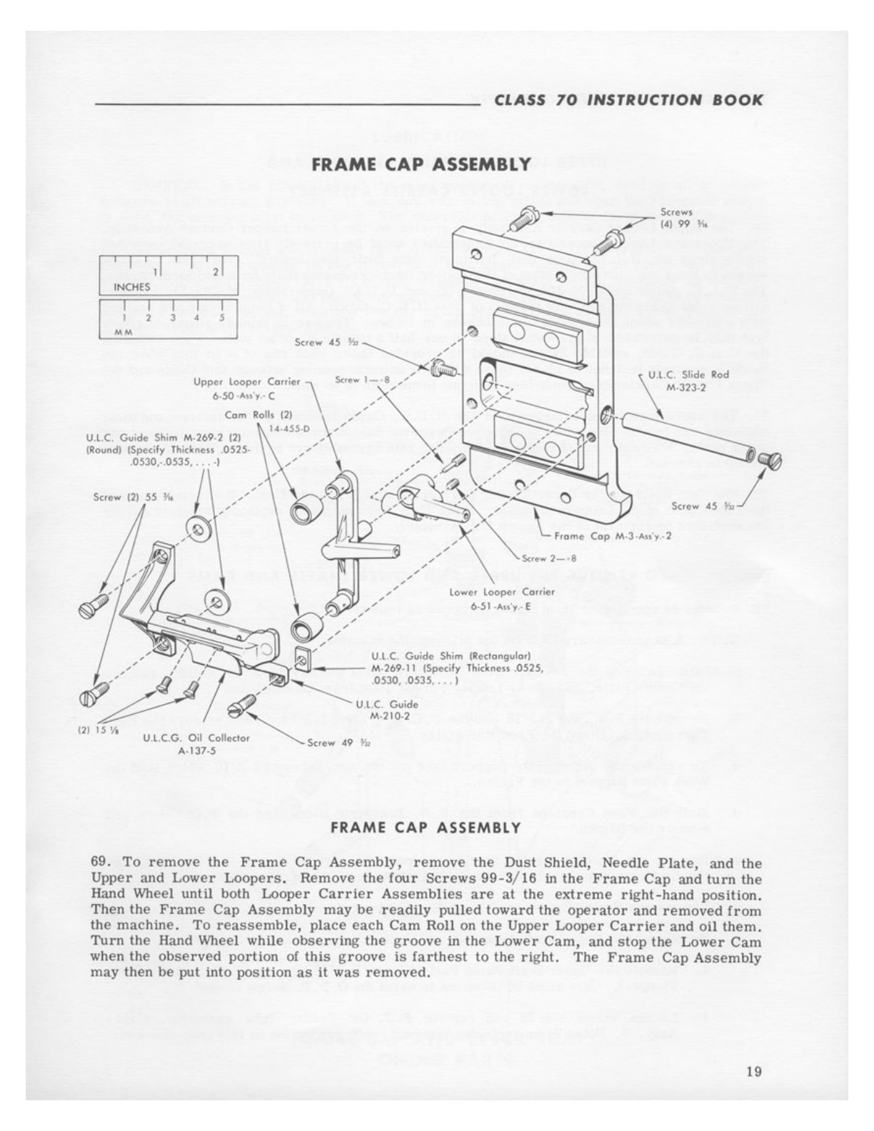
FRAME
CAP ASSEMBLY
Lowe, l
oo
per Carrier
6-51-Au'y.- E
FRAME
CAP AS
SEMBLY
69.
To
remove
the
Frame
Cap
Assembly,
remove
the
Dust Shield, Needle
Plate,
and
the
Upper
and
Lower
Loopers
. Remove
the
four
Screws
99-3/16
in
the
Frame
Cap
and
turn
the
Hand Wheel
until
both
Looper
Carrier
Assemblies
are
al
the
extreme
right-hand
position.
Then
the
Frame
Cap
Assembly
may
be
readily
pulled
toward
the
operator
and
removed
from
the
machine.
To
reassemble,
place
each
Cam
Roll
on
the
Upper
Looper
Carrier
and
oil
them.
Turn
the
Hand Wheel while
observing
the
groove
in
the
Lower
Cam,
and
stop
the
Lower
Cam
when the
observed
portion
of
this
groove
is
farthest
lo
the
right.
The
Frame
Cap
Assembly
may
then
be
put into
position
as
it
was
removed
.
19
From the library of Superior Sewing Machine & Supply LLC - www.supsew.com
THE
MERROW
MACHINE
COMPANY
UPPER
LOOPER
CARRIER
ASSEMBLY
AND
LOWER
LOOPER
CARRIER
ASSEMBLY
70.
The
Upper
Looper
Carrier
Assembly
is
pivoted on the
Lower
Looper
Carrier
Assembly.
The
Upper
and
Lower
Looper
Carrier
Assemblies
must
be
perreclly
free
to
travel
their
full
stroke
along the
U.
L. C. Slide Rod, bul
must
have
little
lost
motion.
The
U.
L.
C. Guide
serves
to
limit
the
sidewise
motion or the
Looper
Carriers
during
their
back
and
forth
stroke.
The U. L.
C.
Guide Shim
M-269-2
(round) (2) and U.
L.
C. Guide Shim M-269-11
(square)
are
provided
under
the
points
of
support
of
this
U.
L.
C.
Guide. All of
these
Shims
are
marked
with a
number
which
designates
its
thickness
in
inches.
Thicker
or
thinner
shims
of
either
type
may
be
purchased
in
graduated
steps
of
one-half
a thousandth of
an
inch.
When
adjusting
the
U.
L.
C. Guide,
suitable
Shims
shou
ld
be
provided
under
each
end of
il
so
that
when the
Guide
is
securely
fastened
in
place,
there
will
be
a
uniform
opening between
this
Guide
and
the
Upper
Looper
Carrier
of
slightly
less
than one thousandth of an
inch.
71.
The
above
mentioned
adjustment
of
the
U. L.
C.
Guide
is
made
at
the
factory
and
most
machines
run
four
or
five
years
without
readjustment
unless
there
be an
accident
spoiling
one
of the
parts.
Whenever any of
the
parts
compiling
this
assembly
are
replaced,
this
adjustment
shou
ld
be
checked.
72.
The
Cam
Rolls
for
the
Upper
Looper
Carrier
Assembly
are
identical.
If
excessive
up
and
down
looseness
of the
Loopers
develops,
these
Cam
Rolls
may
need
replacing
which
is
simply
accomplished
by
removal
of
the
Frame
Cap
Assembly.
TO
REMOVE
THE
UPPER
AND
LOWER
SHAFTS
AND
CAMS
73. In
order
to
remove
the
Main
Shafts,
proceed
as
follows:
20
NOTE:
It
is
unnecessary
to
drain
the
oil
from
tile
machine.
a.
After swinging
the
Presser
Foot
Assembly
out of the way
for
accessibility,
remove
the Needle
Plate,
and
Lower
Looper
Thread
Tube
from
the Machine.
b. Remove
the
F.
E.
Nut
2-3/16
and
the
F.
C. L. (r) Nut
2-3/16
. Then
remove
the
Feed
Carrier
Link
(r)
and
the
Feed
Eccentrics.
c.
To
remove
the
Work
Plate
Support
take
out
the
two
Screws
52-3/16
which hold the
Work
Plate
Support
to
the
Frame.
d.
Slide
the
Feed
Carriers
from
the
F.
R.
Eccentric
Block
and
the
F.
C. Block
and
remove
the
Blocks.
e.
Remove
the
Needle
Carrier
Stud
after
loosening
the
Set
Screw
8-7/32.
Slide
the
Needle
Carrier
Assembly
and
the
N.
C.
Link
Assembly
from
the
machine.
f.
Remove
the
Frame
Cap
Assembly
as
d
escribed
previously.
g.
To
remove
the
Upper Shaft
Assembly
and
Upper
Cam,
proceed
as
follows:
1. Remove
the
Upper Shaft
Pump
Parts
(Screw
8-7/16,
Spring
27-40, and
Oil
Pump
Plunger).
Care
must
be
taken
not
to
harm
the
0.
P.P.
Screw
Casket.
2.
Loosen
Screw
5-9/32
and
remove
F.C.
Oil
Feeder
Tube
Assembly,
M-95-
Assy.
-4.
Note: When
replacing
this
part,
point
projection
on
this
tube downward.
This manual suits for next models
8
Table of contents
Other Merrow Sewing Machine manuals


