Merrow MG Series User manual
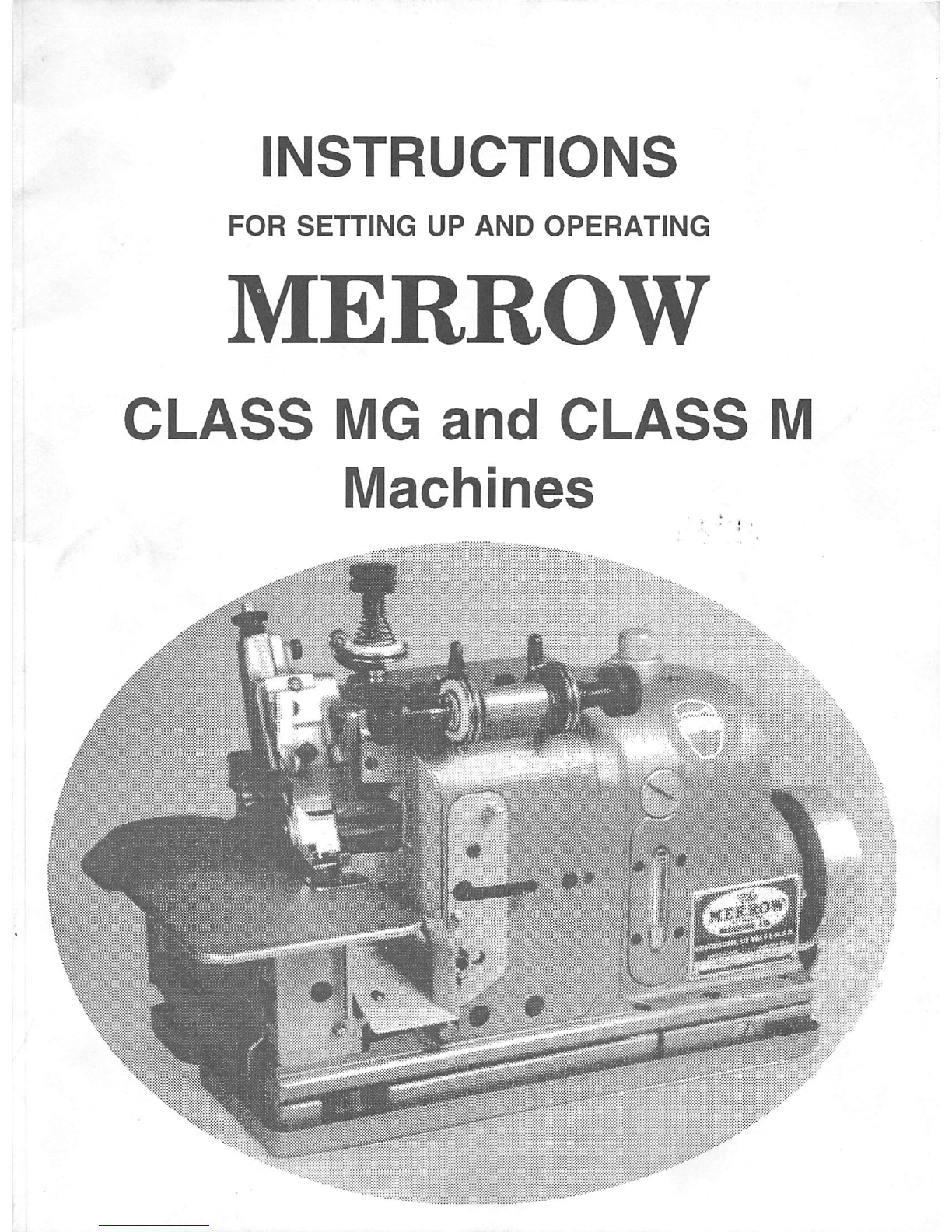
INSTRUCTIONS
FOR
SETTING
UP
AND
OPERATING
MERROW
CLASS
MG
and
CLASS
M
Machines
-y
m
m.
^
From the library of: Superior Sewing Machine & Supply LLC

INTRODUCTION
This book is published for
the
guidance
of
those
persons
responsible for
the
operation
and
maintenance
of Merrow
Class
MG
and
MOverseaming, Overedging,
and
Hemming
Machines. It
contains
diagrams
and
descriptive information concerning
the
most
common
adjustments
necessary
to
assure
maximum production of
the
highest quality. For individual
problems consult your
nearest
Merrow Distributor. Drawings inthis book
are
shown without
the
needle
guard
for clarity. NOTE:
The
machine should not
be
operated
without a
needle
guard. Parts
and
screws
shown
are
common to Class
MG
and
Mmachines. For a more
complete reference
use
the
"Descriptive List of Parts for Merrow
Class
MG
and
Class
M
Machines".
The
Merrow
Class
MG
and
Class
MMachines
are
designed
and
constructed
for
continuous operation at high
speed.
Durability, maximum
utility,
and
versatility
are
primary
qualities of
these
machines. The machines feature an automatic lubrication
system
of
advanced
design
and
the
finest precision parts. Manufacturing to closer tolerances
has
reduced
the
noise
level
of
the
Class
MG
machine.
The
Class
MG
and
Class
M
machines
offer true quality through long
life,
exceptional dependability,
and
superb performance with
aminimum of
maintenance
required.
The
Class
MG
and
Class
M
machines
overseam
and
trim
simultaneously
and
form
one
of
the
following stitch formations: a
one
thread
overseam;
a two
thread
overseam
or
finish; a
three
thread
overseam
or finish or tight
needle
thread
seam;
or a four
thread
(two
needle)
overseam.
The
machines may be
used
on a wide variety of weights (thickness) of
knitted
and
woven
fabrics.
We
also
make
other
classes
of
machines
including
Class
70 Butted
Seaming
Machines,
Plain
Crochet
Machines,
and
Shell Stitch
Crochet
Machines
which
are
being
used
successfully by
manufactures
throughout
the
world.
IMPORTANT:
ALWAYS
WEAR
SAFETY
GLASSES
WHEN
OPERATING
OR
ADJUSTING
THE
MACHINE.
From the library of: Superior Sewing Machine & Supply LLC

HOW
TO
ORDER
Send parts orderto
your
nearest
Merrow
Distributor
orThe
Merrow
Machine
Company, 240
Day
Street
Newington,
CT 06111-1241,
U.S.A.
Phone
(203)
666-0109
FAX
(203)
666-7730
Whenordering replacement parts
include
the
Style
ofthe machine, the Nameofthe part
(see diagrams
included),
and the Letters and
Numbers
stamped on the
part.
The stamping on
aparticular part is
insufficient
information
without
giving
the name of the part.
All
enameled
parts
will
be
furnished
in
green
non-glare
satin
finish,
unless gray is
specified.
To assist
in
ordering, copy and
fill
in
the sample order
form
provided on the back cover.
If
difficulty
is experienced
in
selecting the proper part number desired, we expect to be
able to make a proper selection
from
our records
if
given the
following
information:
(1) The Style and Serial Number of the Machine.
(2) The Name of the Part, and any A/umber stamped on
it.
(3) Special Information
if
the part you request is one of the
following:
(a) Needle
Plates
- specify:
Width of finish desired; long or short finger;
size
of
needle
used,
(number of needle plate is stamped on underside of plate).
(b) Loopers - specify:
Upper or
lower,
one, two or three thread stitch. (Number of looper is
stamped on the shank near the butt end).
(c) Parts for Feed Mechanism - specify:
Single or
double
row.
Front
or rear feed
if
machine has
differential
(gathering) feed.
MERROW
MACHINES
ARE
DISTRIBUTED
BY:
OTHER
MERROW
MACHINES
CLASS
70
BUTTED
SEAMING
MACHINES
PLAIN
CROCHET
MACHINES
BLANKET
HEMMING
MACHINES
SHELL
STITCH
CROCHET
MACHINES
From the library of: Superior Sewing Machine & Supply LLC

THE
MERROW
MACHINE
COMPANY
INDEX
Page
Feed
Mechanism
19-21
Frame
Cap
Assembly 21
How To
Order
3
Introduction 1
Loopers 12
Looper Setting
13-16
Lower Looper Carrier Assembly 21
Lubrication 8
Main
Cams
-Main
Shafts
23-27
Needle
10
Needle Carrier Assembly 10
Needle
Plate
10
Oil List
29
Order
Form
BackCcver
Presser
Foot
and
Presser
Foot Finger 19
Setting Up 6
Speed
6
Threading
16
Upper
and
Lower Cutter Adjustment 18
Upper Looper Carrier Assembly 21, 23
DIAGRAMS
Page
Cleaning Oil Filter 9
Cutter
Mechanism
17
Feed
Mechanism , 20
Frame
Cap
Assembly
22
Loopers
12
Loopers, Bending 15
Loopers, Setting 13, 14
Machine
-
Front
View
5
Machine
-
Rear
View
28
Main
Cams
- Main Shafts 24, 25
Needle Carrier Assembly 11
Oiling
Parts
7
Presser
Foot Assembly 19
From the library of: Superior Sewing Machine & Supply LLC

PRESSERBAR
A-202-1-
P.B.
Catch
M-270-3
P.B.
Catch
LockM-308-1
P.P. Spring
CLASS
MG
AND
CLASS
M
INSTRUCTION
BOOK
HEADM-2-1
Screws (2) 913/16
Head Cap
M-89-2
Screws 36 5/32,53 5/32
Head Cap Extension M-327-6
Screw
15
1/8
Screw
6 3/8
W.P.
StudM-324
1
Screw
10 3/16
W.P.
Plunger
M-198-3
W.P.P.Spring
27*42
WORK
PLATE
M-84-#
Dust
Shield
M*87-#
Screws (2)2 1/8
Screw
13 5/32
Plunger
A-198*1
Frame Cap M-3-1
Screws (4) 99 3/16
FRAME
M-1-#
Screw
30 1/4
Screw
9 7/32
Name
Plate
Model
and
Serial
Number
Screw
38 3/16
Threading Plate (Upper)
M*344-Assy-ff
Screw
1
#6
ThreadingPlate (Lower)
M-345*Assy-(Letter)
Screw
1 #6
FRONT
VIEW
HAND
WHEEL
M*24-2A
Gasket(0-Ring)
M-275-9
Hand
Wliccl
Guard
M*325*9
Screw
18*3/16
Mill
I
II I!
I M I
Ii
CINTIhtlTERS
From the library of: Superior Sewing Machine & Supply LLC

THE
MERROW
MACHINE
COMPANY
INSTRUCTIONS FOR SETTING UP
AND
OPERATING MERROW
HIGH
SPEED
TRIMMING
AND OVERSEAMING MACHINES. CLASS MG AND CLASS M
1.
Upon
removing
the machine
from
its
box
observe
its
threading
carefully
and compare
it
with
the
threading diagram supplied with
the
machine.
Keep
thisthreading
diagram
for
future
reference. The
matter
ofthreading is
very
important
and
if
difficulty
arises, the threading ofthe machineshould be compared
with
the
individual
diagram supplied. Threading is simple, but
it
must be accurate.
2. Secure the machine
mounting
assemblyto the table
with
the three screws
provided.
This
assembly
should
be:
(a) Parallel with
the
center
line of
the
motor.
(b) When the machine is set on the assembly, the front of the machine
will
be three or four
inches back
from
the
front
of the table
with
its hand wheel to the
right
of the operator.
(c)The hand wheel beltgroove should
line
up
with
the motor pulleygroove, when the motor
pulley is in
the
running position.
3. Check the Hand Wheel
(belt)
Guard to be sure
it
does not
hit
the
belt.
Adjust
if
necessary;
by removing screw, repositioning, and replacing screw.
4.
Assemble thread
stand
and
screw
its
base
to
the
table
at
the
rear
of
the
machine.
5.
The
thread guides at
the
top of
the
thread
stand
should
be
directly over
the
center
of
the
cones
of
thread.
6. The thread or yarn should be wound on cones,
which
should stand vertically. The thread
from
these cones should lead up to the Safety Cross Rod (8-52-J) through the thread eyes
and
diagonally downward to the machine. Note: The Safety Cross Rod should be installed
with
the
thread
eyes
below
the
rod.
Care
should
be
taken to
be
sure
the
threads
are
far
enough apart
so
that they
will
not
whip
together when the machine is running at speed.
7. Be
sure
the
thread
will
come
off
the
cones
readily, with uniform tension
and
that it cannot
catch under
the
cone
or elsewhere along its path.
8. Since the
oil
has been drained
from
the machine before shipping, the main reservoir must
be
filled
before the machine is used. (Note section 15)
SPEED
9. The
Merrow
Class
MG
and Class Mmachines are designed to run at a
maximum
speed of
5500 stitches per minute. Some
work
is efficiently handled at 5500 stitches per minute but
it
has been found that
maximum
efficiency for some operations is attained at a speed of
about
5000
stitches
per
minute.
From the library of: Superior Sewing Machine & Supply LLC

CLASS
MG
AND
CLASS
M
INSTRUCTION
BOOK
MOTOR
10. To obtain
full
efficiency the motor must be kept in good operating condition in order to start
and stop the machine
with
minimum
delay. Everyattempt should be made to avoid
driving
the
hand wheel from an oversize pulley, especially when the centers of both pulleys are
relatively close together. Failure to
avoid
this situation can result
in
belt slippage and less
control of starting
and
stopping
the
machine.
11. A V-Belt
Hand
Wheel
with
an
effective pitch
diameter
of 2 1/8" is
supplied
with
each
machine.
A
standard
3/8"
endless
V-Belt
is
recommended
to
connect
the
Hand
Wheel
to
the
motor
pulley.
12. The top of the hand wheel must turn away
from
the operator. The machine
sews
with
clockwise rotation only (when viewed from
the
Hand Wheel).
13. Consult your
nearest
Merrow Distributor to
assure
proper motor
set
up.
Oil
Bubbler
Pipe
Cap
M-333-1
Oil
Bubbler
Pipe
Screw
29
1/4
OIL
FILLER
ASSEMBLY
M-329-Assy-l
UPPER
SHAFT
ASSEMBLY
M-62*Assy-#
UPPER
SHAFT
OIL
COLLECTOR
M-137-2
O.C.
Spring
27-41
OIL
PUMP
PLUNGER
M-198-2
O.P.P.
spring
27-40
O.P.P.
Screw
Gasket
M-275-21
O.P.P.
Screw
8
7/16
OILING
PARTS
Screw
3
9/16
Gasket
M-275-9
INCHES
M 1 1 M
11 2 1 3 1 14> >
5 1
CENTIMETERS
From the library of: Superior Sewing Machine & Supply LLC

THE
MERROW
MACHINE
COMPANY
LUBRICATION
14. General: The lubrication system is entirely automatic, feeding
oil
to all bearing surfaces
without
the
use
of wicks.
The
path of
the
oil
as
it circulates through
the
machine is
described
as
follows: Two
Oil
Pump Plungers
are
operated from eccentric grooves in
the
main shafts. The upper shaft pump draws
oil
from
the
main reservoir
and
forces itthrough
the
Oil Bubbler Pipe to
the
Oil Bubbler Pipe Cap.
The
oil
then drains down through holes
to
the
Upper Shaft Oil Collector
and
the
correct amount of oil is fed into
the
Upper Shaft
Assembly. Inside
the
Upper Shaft
the
oil is distributed through
several
successive
oil holes
and
grooves
to
the
bearing
surfaces
of
the
main shafts on
the
left
end
of
the
machine,
the
Needle Carrier Assembly,
the
Upper Cutter Carrier Assembly,
and
the
Feed
Mechanism.
Some
of
the
oil not fed into
the
Upper Shaft is forced along
the
outside
of
the
Upper
Shaft,
down
the
face
of
the
Cam
Boss,
and
through
holes
in
the
Main
Cams
to
lubricate
the
Cam
Rolls
and
the
Frame
Cap
bearings.
The
Needle
Bearing for
the
Lower
Shaft
is oiled from
the
overflow oil from
the
lower
shaft
pump.
All
the
oil in
the
machine
drains
down
through
the
Oil Filter into
the
Oil Filter Support
and
is
pumped
from this support by
the
lower shaft
pump
back
into
the
oil reservoir.
Note: A special oiling Frame
M-1-A-11
(MG)
or M-1-5
(M)
is available on
request
for high
needle
time operations. This frame provides additional oil to
the
feed mechanism.
15. Oil is filled through a hole under
the
Cap
Screw of
the
Oil
Filler Assembly into
the
main
reservoir. About 8
ounces
of a high grade turbine
oil
is recommended. (Refer to
the
Oil
List
page
24) To drain
the
oil,
remove the machine from the Machine Mounting Assembly
and
extend
the
hand
wheel
end
of
the
machine
over
the
end
of
the
table.
After providing
a
means
of catching
the
oil,
unscrew the
Oil
Drain Screw (#11 3/8) several turns.
16.
The
followino
precautions
are
recommended:
a.) Never allow
the
oil level to
go
below
the
"E"
line on the
Oil
Gage, b.) Occasionally clean the
lint
around the Feed Dogs and
from
behind
the
Dust Shield and Upper Fabric Guard. (Do Not Use
Compressed
Air)
c.) Daily
clean
the
lintfrom
the
drain slots around
the
L.C. Holder Support Assembly, d.) Clean
the
Oil
Filter about once a year (See
Below).
Replace
filter
after four cleanings, e.) Clean
screen
on
the
Oil Filler Assembly
if
filling
the
machine
becomes
difficult
(See
Below).
17. To
clean
the
Oil Filter:
remove
the
three
screws
(#83 3/16) in
the
Oil Filter
Support
and
lift
the
machine
from this support; remove
the
Oil Filter
and
clean with
compressed
air or
solvent.
When
using
compressed
air to clean
the
filter, blow
the
air in
the
reverse
direction
of
the
oil flow - from bottom to
the
top
of
the
Oil Filter. For
best
results
remove
and
replace
the
three
gaskets
on
the
Oil
Filter Support. (O.F.
Gasket
M-275-2, O.F.S.
Gasket
M-275-1,
and
O.F.S. Line Gasket M-275-3) Carefully locate
the
new
gaskets
intheir proper positions,
and
install
the
cleaned
filter (flat
side
down). Lower
the
machine
straight down
onto
the
Oil
Filter
Support
Assembly, being careful not to disturb
the
alignment of
the
gaskets.
Install
and
tighten
the
three
screws
(#83 3/16).
18. To
clean
the
screen
on
the
Oil Filler Assembly:
unscrew
the
entire
assembly
from
the
machine,
remove
the
cap
screw,
and
clean
the
filler
screen
with
compressed
air or solvent.
8
From the library of: Superior Sewing Machine & Supply LLC

1 ^
i
From the library of: Superior Sewing Machine & Supply LLC

THE
MERROW
MACHINE
COMPANY
NEEDLE
19.
Set
the
Needle into
the
Needle Carrier Assembly
so
that
the
end
of
the
shank
of
the
Needle
is in
contact
with
the
Stop
Pin 36-60,
and
tighten
the
Nut 4 3/16 with
the
socket
wrench
firmly.
The beveled portion of this Nut 4 3/16 should be against
the
recess
provided in
the
N.C. Collar. NOTE: The Nut 4 3/16 should only be loosened to
change
the
Needle; it
does
not
have
to
be
removed.
20. A
Needle
as
large
as
practical for
the
work being accomplished should
be
used,
but
care
should
be
taken
that
the
needle
slot in
the
Needle Plate is large
enough
to fit
the
Needle.
21. Self-setting
needles,
marked
with
the
size
number
and
letter "D",
used
on all
styles
of
Class
MG
and
Class
M
machines
are
available in
the
following
sizes:
(from
smallest
to largest)
Nos.
OOOD,
OOD,
OD,
ID, 2D, 3D, 4D, 5D, 6D, 7D,
and
8D.
Special
needles
in
some
of
the
above
sizes
are
available for special
uses.
NEEDLE
CARRIER
ASSEMBLY
22.
The
Needle
Carrier Assembly
must
be perfectly free to swing upon its stud, but
must
not
have any right to left (lateral) movement. To adjust the Needle Carrier Assembly: a.)
Remove
the
Upper Fabric Guard (screw 7 5/32)
and
the
Work
Plate
Support
(remove
screws
36 5/32 from
Feed
Cover Support
and
screws
34
3/16
from Work
Plate
Support),
b.)Loosen
Set
Screw
8 7/32. NOTE:
If
loosening this
screw
is neolected.
damage
to
the
stud
hole in
the
Frame
will
occur, c.) Tighten the Needle Carrier Stud (4 9/32) until it
stops
then
back it out 1/12 of a turn (30 degrees). Tighten
Set
Screw
87/32
and
check
Needle
Carrier for lateral movement.
Repeat
this complete
procedure
as
necessary
until
the
Needle
Carrier
moves
free
up
and
down, but
has
no lateral
movement.
NEEDLE
PLATE
23. Most edging, seaming and serging operations require a Needle Plate with a chaining finger
the
width of
the
stitch
desired
and
sufficiently long to permit two or
three
stitches
to
be
retained
on
the
finger
as
goods
are
fed through
the
machine.
24. A two-thread hemming operation usually requires aNeedle
Plate
with a very short or "stub"
finger. When
such
aNeedle Plate is used,
the
chaining finger is part of
the
presser
foot
finger.
25.
The
needle slot in
the
Needle Plate must always be large enough to permit the blade of
the
needle
to
pass
freely.
The
edge
of this slot should
be
smooth
and
slightly rounded.
The
chaining finger of
the
Needle Plate should be free of burrs.
26.
The
working
surface
of
the
Needle
Plate;
should
be
corrugated
for
standard
sewing
with
differential
feed,
and
smooth
for
use
on delicate fabrics requiring little differential.
27.
The
Needle
Plate
must
match
the
Feeding
Parts
(Note
Section
47).
10
From the library of: Superior Sewing Machine & Supply LLC

CLASS
MG
AND
CLASS
M
INSTRUCTION
BOOK
SET
SCREW
8
7/32
NEEDLE
CARRIER
STUD
Screw
4
9/32
i
Screw
17/64
Needle
Thread
Take Up
NEDLE
CARRIER
M-llO-ASSY.-l
includes:
N.C.
Collar
6-126-B
Bolt
6-128-B
Pin
36-60
IK
N.C. Link Assy.
Plunger
M-198-1
Needle
NEEDLE
CARRIER
ASSEMBLY
Work Plate Support
Screws (2)
34
3/16
Screw
36
5/32
0e
INCHES
1
1
1
2
1
3
1
4
15
1
CENTIMETERS
11
From the library of: Superior Sewing Machine & Supply LLC

THE
MERROW
MACHINE
COMPANY
LOOPERS
28. The Upperand
Lower
Looper
mustco-operate
with
the Needle
in
orderforsewingto occur.
Before
making
any
Loooer
adiustments.alwavs
change
to a
new
Needle.
A
new
Needle
may
solve your problem, without further adjustments.
29. The Upper Loopers are made
in
two general
forms,
one for two thread stitching and the
other
for
three
thread
stitching. Adjustment of both forms
are
the
same.
30. The Loopers are nearly self setting, but they may need slight bending to achieve proper
setting.
Always
bend Loopers
slightly
farther than the
position
you
desire. The Loopers
have a tendency to spring back to their
original
(pre-bent) position,
if
you don't bend them
far enough. Loopers are designed to be bent only
in
the shank area. The point
areas
are
hardened
to prevent wear,
and
do not
take
a
bend
well.
31. To bend the Loopers, we recommend
Merrow
Looper Bender 30-10. Some people use the
shank
of a screwdriver, or pliers to do
the
bending.
Please
note:
If
pliers
are
used, thev
must be smooth surfaced to prevent damage to the surface of the Loopers. A good
light
is recommended for
visibility
when setting the Loopers. A piece of white paper placed
behind
the
Loopers
also
makes
them
more
visible.
12
Sh^
LOWER
LOOPER
NEEDLE
Head
Shank
Blade
Needle
Flat
Spot
Guitd
UPPER
LOOPERS
Slot
TWO
THREAD
Head
t1 c 1
Flat Spot
Shank
f
-J
THREE
THREAD
LOOPER
BENDER
30-10
From the library of: Superior Sewing Machine & Supply LLC

CLASS
MG
AND
CLASS
M
INSTRUCTION
BOOK
LOOPER
SETTING
The
following
instructions are designed to give you a general knowledge of Looper setting.
You
should be able to make any
Merrow
Class
MG
or M machine sew after
following
these
instructions. Specific styles
will
require further
"fine
tuning" to get the ideal looper setting. Talk
to your
local
Merrow
Sales representative fortips on setting your specific style of machine.
32. a. Swingthe Presser Foot Assembly out, and remove the Needle Plate. Remove the Lower
Looper Thread Tube, Feed Dogs, Fabric Guard (Upper), and Dust Shield for
accessibility. Loosen
Set
Screws 1 7/32, 100 3/16
and
remove Loopers.
b. Insert Lower Looper into
the
Lower Looper Carrier.
Push
itdown until it stops. Tighten
Set
Screw 1 7/32 against the flat spot on the shank of the Looper. Note: Before
insertino
new
Looper.
make
sure
the
hole
in
the
Looper
Carrier
and
the
area
around
it
are
clean.
If
vou
push
dirt
into
the
hole.the
Looper
will
stick
out
too
far
and
become
hard
to
adiust
properlv.
If
this
has
happened,
remove
the
Frame
Cap
(Section
50)
and
clean
out
Looper
Carriers
from
the
opposite
end
with
a
wire
or
pipe
cleaner.
c.
Turn
the
Hand
Wheel
so
that
the
Needle
is
at
its furthest
downward
position
(see
diagram 1).
The
distance
between
the
point of
the
Lower Looper
and
the
Needle
should
be
the
thickness of
the
hook
end
of your Merrow
Tweezers
37-225-C, or
about
1/32 of
an
inch (.035). Refer to diagram
"A"
for bending
the
Lower Looper to this setting.
d.
The
top
corner
of
the
needle
point (where
the
point
meets
the
blade)
should
contact
the
needle
guard of
the
Lower Looper with a little
pressure.(See
diagram 2) To
gage
this,
turn
the
Hand
Wheel
to
separate
the
Needle
from
the
Lower Looper. Insert asmall
scrap
piece
of
note-paper
(this is approximately 3
thousandths
of
an
inch thick)
between
the
Needle
and
Lower Looper. Turn
the
Hand Wheel back
so
that
just
the
thickness of
the
paper
is
caught
between
the
Needle
and
Looper. You should
be
able
to remove
the
paper, but you should feel a slight drag against it
as
you pull it out. Refer to
diagram "B" for bending Lower Looper to this setting.
1.)
LOWER
LOOPER
SETTING
DIAGRAMS
1/32"Approximategap
between
Lower
Looper
and
Needle
2.)
Lower Looper
Needle
Guard
(sideview)
Needle
Guard
Point
of
Lower
Looper
against
Scarf
of
Needle
Top View
of
Lower
Looper to Needle
13
From the library of: Superior Sewing Machine & Supply LLC

THE
MERROW
MACHINE
COMPANY
14
e. Turn
the
Hand Wheel slightly,
until
the
point of
the
Lower Looper arrives behind
the
Needle.
The
point of
the
Lower Looper should contact
the
rear
surface
of
the
Needle,
but itshould not deflect
the
Needle.(See diagram 3) The note-paper
gage
used
above,
also
works here. If you
are
using "scarfed" Needle,
the
point of
the
Lower Looper
should still contact, but not deflect the Needle. Generally a Lower Looper is
set
tighter
to a "scarfed" Needle than a standard Needle. Refer to diagram "E"to adjust
the
point
of
the
Lower Looper to
the
Needle.
f.
Insert Upper Looper into the Upper Looper Carrier
as
far
as
it
will
go. Tighten Set
Screw
100 3/16 against
the
flat spot on
the
shank
of
the
Looper.
(See
note
above
in
section
"b")
g. Gently turn Hand Wheel over. The Upper Looper should
be
far
enough
back
that
the
Needle
passes
just behind
the
head.
It should
also
be
far
enough
forward
that
its point
passes
through
the
scarf, just behind
the
eye
of
the
Lower Looper. Look for
interference (contact)
between
the
Upper Looper
and
Needle, or
the
Upper Looper
and
Lower Looper.
The
Upper Looper
should
not
contact
either
the
Needle
or
Lower
Looper. If
there
is contact,
adjust
the
Upper Looper to
clear
the
one
it is contacting. If
it is
contacting
both,
adjust
the
Upper
Looper
to
clear
the
one
with
the
most
interference
first.
To
adjust
the
clearance
of
the
Upper Looper refer to bending
diagrams
"0"
and
"D".
Moving
the
Upper Looper from path 1 to path 2 or 1 to 3 (diagram 4)
will
increase
or
decrease
the
clearance
between
the
Upper Looper
and
the
Needle. It
will
also
do
the
opposite
to
the
clearance
between
the
Upper Looper
and
the
Lower Looper. For
example,
if
moving from path 1 to path 3
increases
your
clearance
between
the
Upper
and
Lower Looper, it
will
also
decrease
your
clearance
between
the
Upper Looper
and
the
Needle.
UPPER
LOOPER
SETTING
DIAGRAMS
3 1 2 ^ ^ Topview
Upper
LoopertoLowerLooper
Oppq
Path
Better
Path
Needle
Path
Upper Looper Path
Lower
Looper
Path
r
3 •
l/2"<
From the library of: Superior Sewing Machine & Supply LLC

A.)
CLASS
MG
AND
CLASS
M
INSTRUCTION
BOOK
Adjusting
the
Upper Looper (Diagram 4) along path 1through points a, b, c, d,
and
e
will
change
the
clearance
between
the
Upper Looper
and
the
Needle.(Bending diagram
0)
Raising
and
lowering
the
Upper Looper affects
the
clearance
by
changing
the
timing of
the
meeting
of
the
Upper Looper
and
the
Needle. Bending
the
Upper
Looper
along
this
path
will
also
change
the
meeting place of
the
point of
the
Upper Looper
and
the
rear
of
the
Lower Looper.
The
point of
the
Upper Looper should fall in
the
scarf of
the
Lower Looper right behind
the
eye.(See
diagram 5
and
6)
The
point of
the
Upper Looper
should not contact
the
Lower Looper. To determine
if
there
is contact, place
the
tip of
your left index finger on the exposed shank of the Lower Looper. Turn the Hand Wheel
slowly
while
holding your finger to the
Looper,
if
there is contact you
will
feel
it.
Adjust
and
recheck
until
the
contact
disappears.
LOOPER
BENDING
DIAGRAMS
B.)
c.)
\
From the library of: Superior Sewing Machine & Supply LLC

THE
MERROW
MACHINE
COMPANY
j.
At
this pointyourLoopers should be reasonably set and
working
with
each other and the
Needle. Two more adjustments can be made, but they
are
generally not necessary.
Diagram 8 shows the angle of the
Lower
Looper, this is pre-set at 3-1/2 degrees.
Following bending diagram F, you can increase or
decrease
this angle to affect the
clearance
between
the
point of
the
Upper Looper
and
the
rear
of
the
Lower Looper.
Diagram 7 shows rotating the head of the Upper Looper. (bending diagram G or H)This
maintains
the
clearance
between
the
Needle
and
the
Upper Looper, while bringing
the
point of
the
Upper Looper closer to or farther
away
from
the
Lower Looper.
k.
When
setting two
needle
machines
like MG-4D-67's follow
the
above
steps,
except
set
the
loopers to
the
inside needle.
The
angle
of
the
Lower Looper
may
have
to
be
reduced
to 2-1/2
degrees
from 3-1/2
degrees
to bring
the
point
closer
to
the
outside
needle
while remaining close to
the
inside needle.
If
the
Upper Looper is blind (no eye)
set
it
as
high
as
possible making
sure
the
point still
clears
the
eye
of
the
Lower Looper.
This
presents
a wider
open
loop of thread for both
needles
to penetrate.
If
the
Upper
Looper is
eyed
it may be
necessary
to
set
the
point lower to
keep
the
thread
loop open
for needle penetration.
It
is more common to have to
follow
head rotation diagrams G
and
Hwhen setting
the
Upper Looper for two needle style machines.
I.
Single thread machines have a
blind
lowerlooper. These are set the
same
as
an eyed
lower looper, except rotatingthe pointto the needle requires the
use
ofdiagram Iinstead
of E. Diagrams A, B,
and
F
can
still
be
used.
THREADING
33. To thread the machine,
follow
the threading diagram provided. (Note Section 1)
When
threading the looper threads,
it
will
be
found
convenient to use a Threading
Wire
(37-318).
Insert
thethread or
yarn
into
theeye
of
the
threading
wire,
pass the
threading
wire
through
the thread eyes and tension discs as shown on the threading diagram. To thread the
Lower
Looper:
Turn
the hand wheel
until
the needle is
in
its highest
position
to locatethe
Lower
Looper's
eye
directly
in
line
with
the
Lower
Looper
Thread
Tube;
pass the
threading
wire
(with
the
lower
looper thread
in
its
eye) through the
Lower
Looper
Thread Tube, and
the eye ofthe
Lower
Looper.
Pull
the
lower
looper
thread
through
to the top ofthe
Needle
Plate.
To thread the
Upper
Looper:
Keep
the
Needle
in
the same
high
position,turn
the
Hand
Wheel
to
position
if
necessary.
Bend
the threading
wire
into
a curve and thread
its
eye
with
the upper looperthread. Insertthe threading
wire
into
the tube
in
the Dust Shield
(in
some cases thistube is
in
the
Frame
Cap).
The
threading
wire
should
comeoutabove
the
Needle
Plate and
in
front
ofthe
Upper
Looper.
Takethe
Upper
Looper
thread
out
of
the threading
wire,
and thread
though
the eye ofthe
Upper
Looper.
Care should be taken
when
threading
the eye
of
the
Upper
Looper.
Always
make
sure
the
thread
is
going
directly
from
the tube to the eye ofthe
looper,
and
NOT
around the
looper.
34.
It
is
generally
advisable
to
keep
the
tension
on
the
threads
as
light
as
possible
to
produce
good results.
Always
make sure the thread
with
the least tension is
still
controlled,
then
adjust the other tensions to balance and
form
the
stitch
you desire.
35.
To
change
the
stitch
formation
consult
your
nearest
Merrow
Distributor.
It
will
benecessary
to change the Threading Plates on the
front
ofthe machine, and
in
some
cases
the Needle
Thread
Take-Up.
16
From the library of: Superior Sewing Machine & Supply LLC

CLASS
MG
AND
CLASS
M
INSTRUCTION
BOOK
CUTTER
MECHANISM
INCHES
1 I 2 I 3
CENTIMETERS
^ \
LOWER
CUTTER
LowerCutter Clamp 6-67
L.C.H.Nut2
5/32
/
Lower
Cutter
Holder
6-65-3
\
v\'L.'y
\W-"
V\^
/-'
>\
V.
U
m
L.C. Holder SupportAssembly M-64-Assyl
includes:
L.C.H.
Clamp
M-66-1
L.C.H.C.
Screw
85 3/16
L.C.H. Spring 27-21
L.C.H.Spring Stop
6-185-A
Screw
2 5/32
Thread
Guide
6-61-B
L.C. Holder Support Shim
UPPER
CUTTER
U.C. Clamp
Screw 385/32(reg cutters)
Screw 375/32(wide cutters)
U.C.
Holder
U.C.
Holder
Clamp
A-97-1/
Screw 81/8 , /
\
.4
Needle
Plate
Screw
81 3/16
^
Screw
55 3/16
^LowerLooperThreadTube
^Thread
Tube
Clamp
Screw
6
5/32
UPPER
CUTTER
CARRIER
ASS'Y
M-52*Assyl
U.C.C.
Thrust
Block
-
M-338-1
From the library of: Superior Sewing Machine & Supply LLC

THE
MERROW
MACHINE
COMPANY
UPPER
AND
LOWER
CUTTER
General
36. The upper and lower cutter may be adjusted up and down and right to
left.
The
standard
setting would
have
them adjusted
so
that
the
fabric going into
the
stitch
will
be
trimmed to
the
width of
the
chaining finger on
the
Needle
Plate.
37.
The
Lower
Cutter
Holder
slides
in
the
L.C.H.
Support
Assembly allowing right to left (lateral)
movement
of
the
Lower Cutter.
Some
lower cutter holders
have
an
internal spring to
maintain
pressure
between
the
Upper
and
Lower Cutter. In
some
cases
you
may
wish to
fix
the
position of
the
lower cutter; to do this, tighten
the
screw
85 3/16 at
the
desired
position. Make
sure
you
are
only applying light
pressure
against
the
upper
cutter.
38.
The
U.C.C.
Thrust
Block
supports
the
force
against
the
upper
cutter
carrier by
the
cutters.
After
extended
service it may be
necessary
to adjust this block by
means
of Adjusting
Screw
81
3/16
and
the
clamp
screw
55 3/16.
There
should
be
about
1
thousandth
of
an
inch of
clearance
between
the
thrust
block
and
the
upper
cutter
carrier.
Adjustment
39.
Set
the
height of the lowercutter so that the cutting edge is slightlyabove the surface ofthe
Needle Plate
and
tighten
the
lower cutter clamp nut 2 5/32. Make
sure
the
height of
the
blade
does
not
interfere
with
the
Presser
Foot.
40. Clamp the
L.
0.
Holder to the
width
of trimming desired by screw 85 3/16. Turn the
Handwheel over
until
the
upper cutter is in its lowest position of travel. At this position,
the
top of
the
cutting
edge
of
the
upper cutter should be even with
the
top of
the
lower cutter's
cutting
edge.
This setting is obtained by adjusting
the
Upper Cutter Clamp
Screw
37
or 38
5/32
and
the
Upper Cutter Holder Clamp Screw 8 1/8.
41. Turn
the
handwheel over again until
the
upper cutter is in its highest position of travel.
The
downward projection of
the
upper cutter must never travel
above
the
height of
the
lower
cutter.
If
it
goes
above
the
lower cutter, you must readjust
the
settings
made
in
step
40
above
to
prevent
the
upper
cutter from breaking
the
lower cutter.
42.
The
two
cutters
must
remain in contact with
each
other
in
order
to
cut
cleanly. Turn
the
Handwheel
so
the
upper
cutter in its
highest
travel position,
and
loosen
the
LC.H.
Clamp
Screw
85 3/16.
Press
the
lower cutter holder lightly to
the
right until
contact
is
made
with
the
upper
cutter
and
tighten
the
L.C.H.C. Screw.
Some
machines
have
spring
type
supports
like
the
one
shown; on this support you only
have
to loosen
the
L.C.H.C. Screw,
and
the
spring applies
the
pressure
needed
to cut. Do not allow
the
lower cutter to
push
to tiohtlv
aoainst
the
uooer
cutter.
If
more
than
light
pressure
is required to
make
a
clean
cut,
the
blades
are
probably dull
and
should be
sharpened
on a Merrow Cutter Grinder.
18
From the library of: Superior Sewing Machine & Supply LLC

CLASS
MG
AND
CLASS
M
INSTRUCTION
BOOK
PRESSER
FOOT
AND
PRESSER
FOOT
FINGER
43.
The
center
hinged
type
Presser
Foot is generally
used
since
it is convenient for
seaming,
or
edging
where
seams
or thick
and
thin
places
must
be
crossed.
Rigid
and
rear
hinged
type
presser
feet
are
available for special
purposes.
After lifting
the
Presser
Foot Latch,
the
Presser
Foot
Arm with its
Presser
Foot
may
be
swung
out to provide
access
to
the
needle
and
loopers.
44. A "stub" or short
Presser
Foot Finger is
used
if
the machine is equipped with a Needle Plate
with a chaining finger. A long P.P. Finger is
used
with a Needle Plate with a
stub
or short
chaining finger.
The
finger
guards
the
right
side
of
the
needle.
This
should
be
adjusted
sideways
so
that
the
left
hand
edge
of
the
finger (next to
the
needle)
just
clears
the
needle
when
the
needle
is in
the
full
down
position.
45. Ordinarily,
use
as
little
pressure
on
the
Presser
Foot
as
possible. This
pressure
is
adjustable by
the
Screw
6 3/8. A
set
Screw 13 5/32 holds
Screw
63/8 in position
so
your
adjustment
does
not
change
while
the
machine is running.
Presser
Foot
Arm
A-206-*
Presser
Foot
A-71-*
P.P. Finger
A-106-*
6-106-*
P.P. Uncurling Block
A-114-*
6-114-*
P.P. Hinge Spnng
A-125-*
6-125
Needle
Guard
M-374-1
Screws
(2)
5
3/32
Washers
(2)
2
3/32
PRESSER
FOOT
ASSEMBLY
FEEDING
MECHANISM
46. Feed Dogs are normally provided
with
either coarse or fine cut teeth, single rowor double
row,
depending on the material you are sewing. Generallythe Feed Dogs should be set
as
low
as
practicalto
allow
the
work
to feed. The length offeed can be changed by removing
the Feed Eccentric and substituting an eccentric of shorter or longer stroke. Feed
Eccentrics (6-82-#) are marked to indicate approximately the number of stitches per
inch
produced
at
the
edge
of
the
fabric.
19
From the library of: Superior Sewing Machine & Supply LLC

1
M-74-2
F.C.L.Bushing (F)
M-79-2
LINK(R)
Needle
Plate
0
prevent
inter
i
F.C.
Block
Pin
M-94-1
From the library of: Superior Sewing Machine & Supply LLC
This manual suits for next models
1
Table of contents
Other Merrow Sewing Machine manuals