pro bel Freeway Series User manual

r
ro
o-
-B
Be
el
l
L
Lt
td
d
F
Fr
re
ee
ew
wa
ay
y
R
Ra
an
ng
ge
e
S
Sy
ys
st
te
em
m
U
Us
se
er
r
G
Gu
ui
id
de
e
U
U-
-F
Fr
re
ee
ew
wa
ay
y
R
Ra
an
ng
ge
e
S
Sy
ys
st
te
em
m
U
Us
se
er
r
G
Gu
ui
id
de
e
1
1
o
on
nt
te
en
nt
ts
s
1
1
I
In
nt
tr
ro
od
du
uc
ct
ti
io
on
n
5
5
1.1 General points 5
1.2 Control 6
1.3 Environmental 6
1.4 Problems? 6
1.5 The right choice 7
2
2
I
I
n
n
s
s
t
t
a
a
l
l
l
l
a
a
t
t
i
i
o
o
n
n
9
9
2.1 Door removal 9
2.2 Power supply removal 10
2.3 Signal rear panel removal 12
2.4 Removal and replacement of modules 13
2.5 Cable connections 14
2.6 Control rear panel connections 16
2.7 Video references - BNC sockets (looping) 18
2.8 Setting the AES reference 19
2.9 Setting the level switch 20
2.10 Setting the destination assign switch 22
2.11 LED indications 22
2.12
reeway
control card 24
2.13 Setting the reset switch 26
3
3
H
Ha
ar
rd
dw
wa
ar
re
e
c
co
on
nf
fi
ig
gu
ur
ra
at
ti
io
on
n
2
27
7
3.1 Router details 27
3.2 Port definitions 31
3.3 Controller configuration 33
3.4 Software controllable processes 35
4
4
C
Co
on
nt
tr
ro
ol
l
s
sy
ys
st
te
em
m
o
op
pe
er
ra
at
ti
io
on
n
3
37
7
4.1 Master and slave module details 37
4.2 Master router dual control and changeover 37
4.3 Operating modes 38

F
Fr
re
ee
ew
wa
ay
y
R
Ra
an
ng
ge
e
S
Sy
ys
st
te
em
m
U
Us
se
er
r
G
Gu
ui
id
de
e
r
ro
o-
-B
Be
el
l
L
Lt
td
d
2
2
U
U-
-F
Fr
re
ee
ew
wa
ay
y
R
Ra
an
ng
ge
e
S
Sy
ys
st
te
em
m
U
Us
se
er
r
G
Gu
ui
id
de
e
5
5
R
Ro
ou
ut
ti
in
ng
g
4
43
3
5.1 Setting crosspoints 43
5.2 Salvo switching 43
5.3 andshaking and error reporting 44
5.4 Defining stereo analogue audio parameters 45
5.5 Using PC based editors 47
5.6 Configuring the database 48
5.7 Understanding the database 54
6
6
a
an
ne
el
l
d
de
et
ta
ai
il
ls
s
5
59
9
6.1 Summary of panel types 59
6.2 General panel details 60
6.3 Panel features 60
6.4 Panel types 70
6.5 Configuration via panels 82
7
7
L
Le
ev
ve
el
l
t
ty
yp
pe
es
s
8
87
7
7.1 Normal
reeway
(64x64) 87
7.2 YUV
reeway
(5x5, 10x10, 15x15 or 20x20) 87
7.3 Dual channel
reeway
(8x8, 16x16, 24x24 or 32x32) 88
7.4 Quad channel
reeway
(4x4, 8x8, 12x12 or 16x16) 89
7.5 Machine control
reeway
(17x16, 33x32, 49x48, 65x64) 89
7.6 Normal TM32 and TM16 89
7.7 YUV TM32 and TM16 (5x5, 10x5 or 10x10) 89
7.8 Dual channel TM32 and TM16 (8x8 or 16x16) 90
7.9 Quad channel TM32 and TM16 (4x4 or 8x8) 91
7.10 Normal TM24 (24x6, 24x12 or 24x24) 92
7.11 Dual channel TM24 (12x6 or 12x12) 92
7.12 YUV TM24 (8x2 or 8x8) 92
8
8
T
Th
he
e
F
Fr
re
ee
ew
wa
ay
y
w
wi
in
nd
do
ow
ws
s
e
ed
di
it
to
or
r
9
93
3
8.1 ardware requirements 93
8.2 Installing the editors 93
9
9
r
ro
ob
bl
le
em
m
s
so
ol
lv
vi
in
ng
g
9
95
5
1
10
0
S
Sp
pe
ec
ci
if
fi
ic
ca
at
ti
io
on
n
9
99
9

r
ro
o-
-B
Be
el
l
L
Lt
td
d
T
Te
ec
ch
hn
ni
ic
ca
al
l
m
ma
an
nu
ua
al
l
U
U-
-F
Fr
re
ee
ew
wa
ay
y
R
Ra
an
ng
ge
e
S
Sy
ys
st
te
em
m
U
Us
se
er
r
G
Gu
ui
id
de
e
3
3
1
11
1
S
Su
up
pp
po
or
rt
t
i
in
nf
fo
or
rm
ma
at
ti
io
on
n
1
10
01
1
11.1 Warranty information 101
11.2 Telephone support 102
11.3 Contacting our support departments 103
11.4 Equipment repairs 104
11.5 Equipment loans 105
11.6 Equipment exchanges 105
11.7 Sending equipment to Pro-Bel 106
1
12
2
I
Im
mp
po
or
rt
ta
an
nt
t
s
sa
af
fe
eg
gu
ua
ar
rd
ds
s
1
10
07
7
12.1 Checking the equipment 107
12.2 Safety guidelines 107
12.3 Cautions 109
1
13
3
E
EM
MC
C
c
co
om
mp
pl
li
ia
an
nc
ce
e
i
in
nf
fo
or
rm
ma
at
ti
io
on
n
1
11
11
1

F
Fr
re
ee
ew
wa
ay
y
R
Ra
an
ng
ge
e
S
Sy
ys
st
te
em
m
U
Us
se
er
r
G
Gu
ui
id
de
e
r
ro
o-
-B
Be
el
l
L
Lt
td
d
4
4
U
U-
-F
Fr
re
ee
ew
wa
ay
y
R
Ra
an
ng
ge
e
S
Sy
ys
st
te
em
m
U
Us
se
er
r
G
Gu
ui
id
de
e

r
ro
o-
-B
Be
el
l
L
Lt
td
d
T
Te
ec
ch
hn
ni
ic
ca
al
l
m
ma
an
nu
ua
al
l
U
U-
-F
Fr
re
ee
ew
wa
ay
y
R
Ra
an
ng
ge
e
S
Sy
ys
st
te
em
m
U
Us
se
er
r
G
Gu
ui
id
de
e
5
5
1
1
I
In
nt
tr
ro
od
du
uc
ct
ti
io
on
n
he reeway series range of routing switchers addresses today's need for the
smaller installation whilst offering the high performance, cost effective, multi signal-
format, routing offered by Pro-Bel.
his guide describes the common features of reeway (chassis, control card, PSU,
etc.). he first part of this User Guide details installation and configuration
information irrespective of specific signal type. he remaining parts cover each of
the specific signal types in turn.
n
n
1
1.
.1
1
G
Ge
en
ne
er
ra
al
l
p
po
oi
in
nt
ts
s
reeway routers are available in three family types, reeway 32, reeway 64 and
reeway 128, each family type offers a range of configuration sizes up to a
maximum defined by the family number, that is, 32x32, 64x64 or 128x128
respectively. reeway 32 and 64 are available for all signal variants, but the reeway
128 range is only available in audio, RS422 and timecode formats. In addition
reeway input cards, providing 16 channel input modules, may be used with any of
the video and audio routers in the Freeway 32, 64 or 128 ranges. I n using these
input modules with the standard signal cards, each range can be configured to
provide routers from 16x16 to the maximum permitted size for each range in either
16input or 16 input/ output blocks.
By designing each signal-type module to require identical PSU and support functions,
any combination of signal types may be housed in the same chassis. So that, for
instance, a 32x32 SDV and stereo audio switcher can be housed within the same
frame.
wo frame variants are available for the Freeway range, one 3U; accommodating a
total of 4 signal cards, while the 6U variant houses up to 8. ypically, Freeway 32 and
64 routers along with the Freeway 128 RS422 and timecode systems use the 3U,
whilst Freeway 128 audio routers use the 6U frame. However, as these frames can
accommodate any modules in the Freeway range, smaller audio routers may be
housed in the 3U frame while Freeway 32 and 64 cards can share a 6U frame with
Freeway 128 modules.
reeway's modularity ensures that your switcher can change as your requirements
do, permitting routers to be ‘plug and play’ upgraded in the field to their maximum
size. Similarly a predominantly analogue router can gradually be ‘transformed’ into a
digital router (by swapping analogue sixteen square modules for digital alternatives)
as your installation requirements evolve. In Chapter 3 we'll tell you how to get your

F
Fr
re
ee
ew
wa
ay
y
R
Ra
an
ng
ge
e
S
Sy
ys
st
te
em
m
U
Us
se
er
r
G
Gu
ui
id
de
e
r
ro
o-
-B
Be
el
l
L
Lt
td
d
6
6
U
U-
-F
Fr
re
ee
ew
wa
ay
y
R
Ra
an
ng
ge
e
S
Sy
ys
st
te
em
m
U
Us
se
er
r
G
Gu
ui
id
de
e
router ‘up and running’ and, in Chapter 4, how to configure the system for your
present needs and future expansion.
n
n
1
1.
.2
2
o
on
nt
tr
ro
ol
l
Control for the router is provided by an internal daughter card. Optionally a second
control card can be fitted thereby providing a back-up controller should the primary
card fail. reeway's control system offers extensive facilities, supporting up to 32
panels or under monitor displays. Panel types may be XY, button-per-crosspoint or
multibus. Internal database editing functions provide extensive system configuration
options including; programmable salvos, source and destination associations,
marrying, route protects and inhibits, audio channel configurations and overrides.
Up to 8 levels of reeway routing may be slaved to the main frame by means of a
parallel control link. A special version of this parallel link is also available to slave
existing M Series routers. Extensive details of the reeway control system (and how
to edit the internal database information) are given in Chapters 4, 5 and 6.
n
n
1
1.
.3
3
E
En
nv
vi
ir
ro
on
nm
me
en
nt
ta
al
l
By utilising advanced PSU circuit topology and the latest signal switching
technologies, reeway offers a very compact router with low power dissipation,
ensuring ‘fit and forget’ reliability. For extra security, each frame has provision for
redundant PSU modules, providing a main and backup architecture in the event of a
PSU failure. he high-speed converter technology in the PSU is monitored by two on-
board microprocessors that assess the condition of the mains and of the supplies
leaving the power unit. Should any of the PSUs ‘vital-signs’ show a warning condition
these are monitored and, if appropriate, an external warning alarm may be activated.
reeway PSUs may be withdrawn from the unit from the front and a replacement
‘hot-plugged’; thereby ensuring continuous service. For details, see Chapter 3.
n
n
1
1.
.4
4
P
Pr
ro
ob
bl
le
em
ms
s?
?
We hope you won't have them! Perhaps it's ‘finger-trouble’… or something more
serious? In Chapter 14 you'll find a problem solving guide to help you with possible
questions. You'll also find contact information for our Customer Service department
in Chapter 2.
ote: This product contains no user servicable parts; should this product require
servicing please refer to Pro-Bel or your local agent.

r
ro
o-
-B
Be
el
l
L
Lt
td
d
T
Te
ec
ch
hn
ni
ic
ca
al
l
m
ma
an
nu
ua
al
l
U
U-
-F
Fr
re
ee
ew
wa
ay
y
R
Ra
an
ng
ge
e
S
Sy
ys
st
te
em
m
U
Us
se
er
r
G
Gu
ui
id
de
e
7
7
n
n
1
1.
.5
5
T
Th
he
e
r
ri
ig
gh
ht
t
c
ch
ho
oi
ic
ce
e
Choosing a switcher is an important decision, no-one wants to get it wrong. With all
the changes in television production today, you need a router that can evolve and
change. hat's why we developed reeway, the future-proofed modular multi-format
routing system that provides you with the smoothest ride to the future.
We’re glad you agree with us.
The Freeway Team

F
Fr
re
ee
ew
wa
ay
y
R
Ra
an
ng
ge
e
S
Sy
ys
st
te
em
m
U
Us
se
er
r
G
Gu
ui
id
de
e
r
ro
o-
-B
Be
el
l
L
Lt
td
d
8
8
U
U-
-F
Fr
re
ee
ew
wa
ay
y
R
Ra
an
ng
ge
e
S
Sy
ys
st
te
em
m
U
Us
se
er
r
G
Gu
ui
id
de
e

r
ro
o-
-B
Be
el
l
L
Lt
td
d
T
Te
ec
ch
hn
ni
ic
ca
al
l
m
ma
an
nu
ua
al
l
U
U-
-F
Fr
re
ee
ew
wa
ay
y
R
Ra
an
ng
ge
e
S
Sy
ys
st
te
em
m
U
Us
se
er
r
G
Gu
ui
id
de
e
9
9
2
2
I
In
ns
st
ta
al
ll
la
at
ti
io
on
n
Any Pro-Bel equipment may be mounted next to other equipment provided it is not
subjected to excessive heat from that equipment. In order to maintain a cool,
internal temperature, make sure that the fans (if fitted) and vents on either side of
the equipment are unobstructed. Proper air circulation requires that both the fans
and vents have access to the ambient temperature room air mass.
During the installation process it is important to observe the following points:
· do not obstruct the vents on the unit to allow cooling to take place
· remove shipping brackets
n
n
2
2.
.1
1
D
Do
oo
or
r
r
re
em
mo
ov
va
al
l
he frame has a horizontally hinged front panel door that can be opened by turning
the knob anti-clockwise. he door can be removed from the frame by opening it
approximately 30° and lifting upwards. It will not disconnect from the hinge at a
greater angle.
For correct re-fitting of the door, ensure that it is centrally located on the hinge.

F
Fr
re
ee
ew
wa
ay
y
R
Ra
an
ng
ge
e
S
Sy
ys
st
te
em
m
U
Us
se
er
r
G
Gu
ui
id
de
e
r
ro
o-
-B
Be
el
l
L
Lt
td
d
1
10
0
U
U-
-F
Fr
re
ee
ew
wa
ay
y
R
Ra
an
ng
ge
e
S
Sy
ys
st
te
em
m
U
Us
se
er
r
G
Gu
ui
id
de
e
n
n
2
2.
.2
2
P
Po
ow
we
er
r
s
su
up
pp
pl
ly
y
r
re
em
mo
ov
va
al
l
here are two power supply modules used for main and backup. For EMC and safety
reasons the mains, chassis and signal earths are permanently connected together
with the module.
A green LED on each PSU indicates the status of the power supply. PSU relay alarms
are also fitted.
he power supply modules are push fit into the frame and each secured by two
screws on the rear of the frame.
When replacing the power supply the following recommendations must be observed:
· always disconnect the mains from the unit before removal or during repair
· the securing screws should always be fitted before connecting the mains to
provide essential chassis earthing
ote: The reeway PSU automatically adapts to the voltage range supplied. There is no
need to set a mains voltage selector position.
WARNING: The screws form an essential chassis connection for
EMC compliance and must not be omitted
Power OK
Green LED
Power OK
Green LED

r
ro
o-
-B
Be
el
l
L
Lt
td
d
T
Te
ec
ch
hn
ni
ic
ca
al
l
m
ma
an
nu
ua
al
l
U
U-
-F
Fr
re
ee
ew
wa
ay
y
R
Ra
an
ng
ge
e
S
Sy
ys
st
te
em
m
U
Us
se
er
r
G
Gu
ui
id
de
e
1
11
1
Position of PSU fixing screws
on rear of panel

F
Fr
re
ee
ew
wa
ay
y
R
Ra
an
ng
ge
e
S
Sy
ys
st
te
em
m
U
Us
se
er
r
G
Gu
ui
id
de
e
r
ro
o-
-B
Be
el
l
L
Lt
td
d
1
12
2
U
U-
-F
Fr
re
ee
ew
wa
ay
y
R
Ra
an
ng
ge
e
S
Sy
ys
st
te
em
m
U
Us
se
er
r
G
Gu
ui
id
de
e
n
n
2
2.
.3
3
S
Si
ig
gn
na
al
l
r
re
ea
ar
r
p
pa
an
ne
el
l
r
re
em
mo
ov
va
al
l
Connections to the outside world are made through panels on the rear of the frame.
he control rear panel is common throughout the reeway range and is fixed.
he signal rear panels are easily removed in the following manner:
· disconnect power from the frame
· remove the screws
· gently pull panel out
· replace panel and screws ensuring a good fit is made for EMC compliance
he connection details for the rear panels supplied are described in the appropriate
section of this User Guide.
Signal rear panels
Screws

r
ro
o-
-B
Be
el
l
L
Lt
td
d
T
Te
ec
ch
hn
ni
ic
ca
al
l
m
ma
an
nu
ua
al
l
U
U-
-F
Fr
re
ee
ew
wa
ay
y
R
Ra
an
ng
ge
e
S
Sy
ys
st
te
em
m
U
Us
se
er
r
G
Gu
ui
id
de
e
1
13
3
n
n
2
2.
.4
4
R
Re
em
mo
ov
va
al
l
a
an
nd
d
r
re
ep
pl
la
ac
ce
em
me
en
nt
t
o
of
f
m
mo
od
du
ul
le
es
s
he modules can be removed and replaced from the frame, powered or un-powered,
using the following procedure. For removal purposes it is advisable to remove the
ribbon cables first and then the cards.
· release the ribbon cables by pushing the catches up on either end of the
connector as shown
· lift up the card ejector on the module and gently pull the card out
Replacement is the reverse of above:
· slide the card along the guide rail of the required slot, gently pushing it fully
home until it marries up with the connector on the motherboard
· if a card has a board reset button (eg 4744 card), this should be pressed after the
board has been plugged in
Catches (Push up to release)
Top view
Front view
Side view
F
Fr
re
ee
ew
wa
ay
y
R
Ra
an
ng
ge
e
S
Sy
ys
st
te
em
m
U
Us
se
er
r
G
Gu
ui
id
de
e
r
ro
o-
-B
Be
el
l
L
Lt
td
d
1
14
4
U
U-
-F
Fr
re
ee
ew
wa
ay
y
R
Ra
an
ng
ge
e
S
Sy
ys
st
te
em
m
U
Us
se
er
r
G
Gu
ui
id
de
e
n
n
2
2.
.5
5
a
ab
bl
le
e
c
co
on
nn
ne
ec
ct
ti
io
on
ns
s
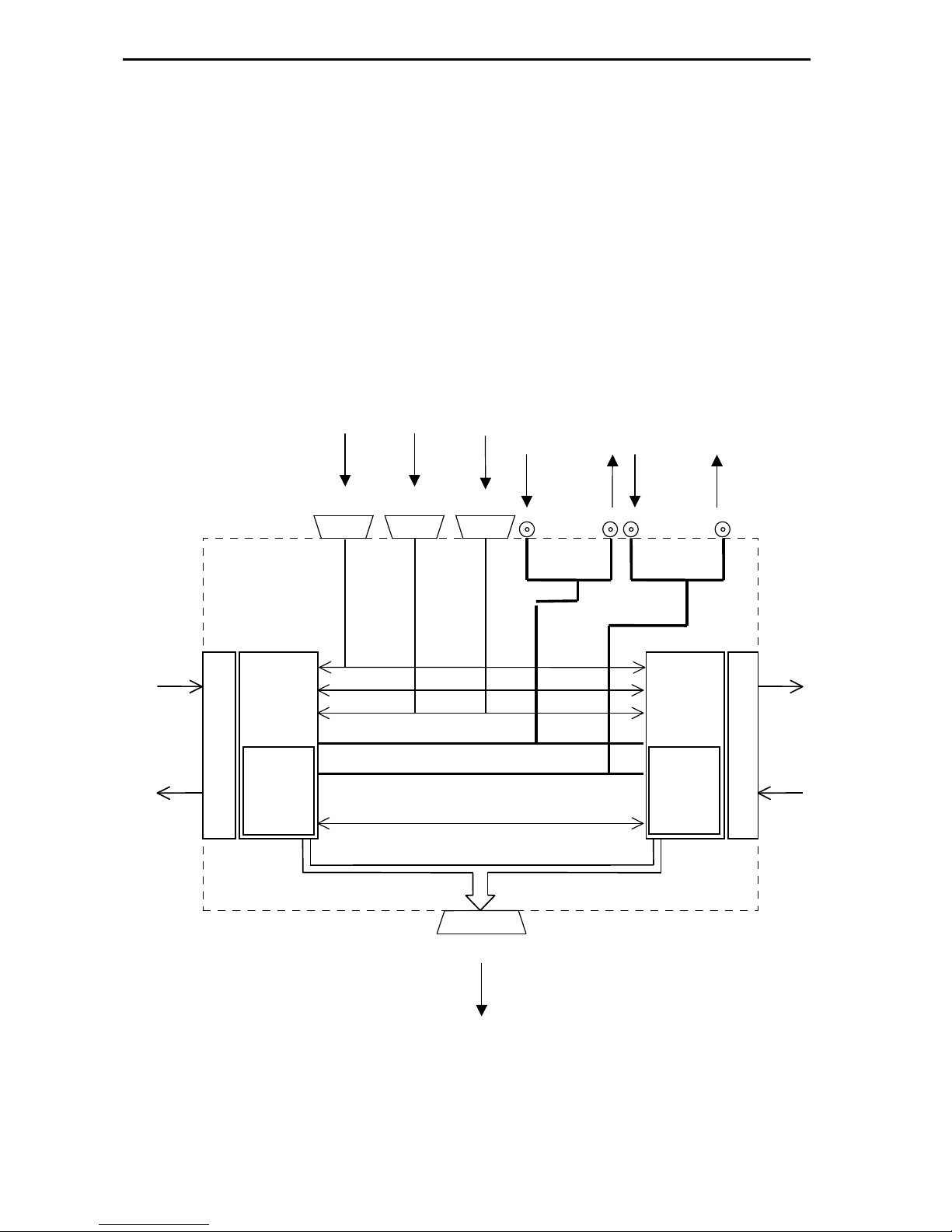
he standard cable connections diagram for a reeway router is shown below.
Note: he reeway router can be controlled from multidropped panels (i.e. a chain of
panels on a common pin-to-pin cable bus, each set to a different address) on ports
RS485-1 and RS485-2 or from control systems on point to point links.
Master
2440
control
submodule
37 way
Video ref 2
(looping)
Video ref 1
(looping)
Control
Parallel xpt bus
(to slave routers)
9 way
RS232
PC editor
or remote
control port
9 way
RS485
General
remote/
panel port 2
9 way
RS485
General
remote/
panel port 1
reeway
router
modules
p
a
n
e
l
s
R
e
a
r
reeway
router
modules
Slave
2440
control
submodule
525 NTSC
or TTLpulse
625 PAL
Inter processor
(Serial comms)
Inputs
Outputs
Outputs
Inputs
p
a
n
e
l
s
R
e
a
r

r
ro
o-
-B
Be
el
l
L
Lt
td
d
T
Te
ec
ch
hn
ni
ic
ca
al
l
m
ma
an
nu
ua
al
l
U
U-
-F
Fr
re
ee
ew
wa
ay
y
R
Ra
an
ng
ge
e
S
Sy
ys
st
te
em
m
U
Us
se
er
r
G
Gu
ui
id
de
e
1
15
5
he following diagrams show the position of these connectors on the rear of both the
3U and 6U reeway frames.
Unbalanced
AES ref
Video ref
525
625
RS485
1
2
PSU
monit
or
CTRL bus
AES ref
R
RS
S2
23
32
2

F
Fr
re
ee
ew
wa
ay
y
R
Ra
an
ng
ge
e
S
Sy
ys
st
te
em
m
U
Us
se
er
r
G
Gu
ui
id
de
e
r
ro
o-
-B
Be
el
l
L
Lt
td
d
1
16
6
U
U-
-F
Fr
re
ee
ew
wa
ay
y
R
Ra
an
ng
ge
e
S
Sy
ys
st
te
em
m
U
Us
se
er
r
G
Gu
ui
id
de
e
n
n
2
2.
.6
6
o
on
nt
tr
ro
ol
l
r
re
ea
ar
r
p
pa
an
ne
el
l
c
co
on
nn
ne
ec
ct
ti
io
on
ns
s
‘
‘
O
ON
NT
TR
RO
OL
L’
’
c
co
on
nn
ne
ec
ct
to
or
r
p
pi
in
no
ou
ut
t
37 way ‘D’ type fixed socket on frame
Pin
Function Pin
Function
1 ENABLE 20 H/SHAKE
2 LEVEL A3 21 LEVEL A2
3 LEVEL A1 22 LEVEL A0
4 DES A6 23 DES A5
5 DES A4 24 DES A3
6 DES A2 25 DES A1
7 DES A0 26 A6 SOURCE
8 A5 SOURCE 27 A4 SOURCE
9 A3 SOURCE 28 A2 SOURCE
10 A1 SOURCE 29 A0 SOURCE
11 AUDO 30 AUD1
12 AUD2 31 F/SYNC
13 SROBE 32 N/C
14 N/C 33 N/C
15 N/C 34 N/C
16 N/C 35 N/C
17 N/C 36 N/C
18 N/C 37 CHASSIS
19 CHASSIS

r
ro
o-
-B
Be
el
l
L
Lt
td
d
T
Te
ec
ch
hn
ni
ic
ca
al
l
m
ma
an
nu
ua
al
l
U
U-
-F
Fr
re
ee
ew
wa
ay
y
R
Ra
an
ng
ge
e
S
Sy
ys
st
te
em
m
U
Us
se
er
r
G
Gu
ui
id
de
e
1
17
7
‘
‘R
RS
S4
48
85
5-
-1
1’
’
a
an
nd
d
‘
‘R
RS
S4
48
85
5-
-2
2’
’
c
co
on
nn
ne
ec
ct
to
or
r
p
pi
in
no
ou
ut
ts
s
9 way ‘D’ type fixed sockets on frame.
Pin Pinout of socket when connected to:
Panels C
Co
on
nt
tr
ro
ol
l
s
sy
ys
st
te
em
m
1 CHASSIS CHASSIS
2 Rx- x-
3 x+ Rx+
4 0V 0V
5 n/c n/c
6 0V 0V
7 Rx+ x+
8 x- Rx-
9 CHASSIS CHASSIS
‘
‘R
RS
S2
23
32
2’
’
a
an
nd
d
‘
‘E
ED
DI
IT
TO
OR
R’
’
c
co
on
nn
ne
ec
ct
to
or
r
p
pi
in
no
ou
ut
ts
s
9 way ‘D’ type fixed sockets on frame.
Pin Function
1 N/C
2 Rx
3 x
4 N/C
5 0V
6 DR COMMON
7 RS
8 C S
9 N/C

F
Fr
re
ee
ew
wa
ay
y
R
Ra
an
ng
ge
e
S
Sy
ys
st
te
em
m
U
Us
se
er
r
G
Gu
ui
id
de
e
r
ro
o-
-B
Be
el
l
L
Lt
td
d
1
18
8
U
U-
-F
Fr
re
ee
ew
wa
ay
y
R
Ra
an
ng
ge
e
S
Sy
ys
st
te
em
m
U
Us
se
er
r
G
Gu
ui
id
de
e
‘
‘P
PS
SU
U’
’
m
mo
on
ni
it
to
or
r
p
pi
in
no
ou
ut
ts
s
9 way ‘D’ type fixed socket on frame.
Pin Function
1 CHASSIS
2 PSU 1 RELAY COM
3 PSU 1 RELAY S/C FAIL
4 PSU 1 RELAY O/C FAIL
5 PSU 2 RELAY COM
6 PSU RELAY S/C FAIL
7 PSU RELAY O/C FAIL
8 N/C
9 N/C
S/C - Closed in fail condition
O/C - Open in fail condition
n
n
2
2.
.7
7
V
Vi
id
de
eo
o
r
re
ef
fe
er
re
en
nc
ce
es
s
-
-
B
BN
N
s
so
oc
ck
ke
et
ts
s
(
(l
lo
oo
op
pi
in
ng
g)
)
reeway can handle video signals of either 525/60 standard or 625/50 standard
(analogue or digital). Some users wish to route both types of signal simultaneously.
Most routers only provide for a single video ‘house reference’ and this presents a
problem because a PAL reference cannot be used to ensure vertical (‘flash-less’)
switching of a 525/60 signal. he converse is also true. reeway delivers maximum
flexibility by providing inputs for both PAL and N SC ‘house reference’ signals.
Ideally colour-black, the ref signal may also be any stable video signal. Users may
assign which inputs are 525/60, and which are 625/50 via the configuration editor
(described later in this manual).

r
ro
o-
-B
Be
el
l
L
Lt
td
d
T
Te
ec
ch
hn
ni
ic
ca
al
l
m
ma
an
nu
ua
al
l
U
U-
-F
Fr
re
ee
ew
wa
ay
y
R
Ra
an
ng
ge
e
S
Sy
ys
st
te
em
m
U
Us
se
er
r
G
Gu
ui
id
de
e
1
19
9
n
n
2
2.
.8
8
S
Se
et
tt
ti
in
ng
g
t
th
he
e
A
AE
ES
S
r
re
ef
fe
er
re
en
nc
ce
e
In order to perform ‘click-less’ switching of digital audio signals, a ‘cut’ must be made
during a point in the data stream when no audio is present (usually during a pre-
amble). For this to happen, the switcher must receive a digital audio reference signal
synchronous with the audio signals arriving at the frame.
Note that an audio cut is performed at the first appropriate instant following a
television field boundary (as derived from the video reference input).
he reeway router can be configured to accept an unbalanced digital audio
reference, via the unbalanced AES reference BNC. In this case a ‘dummy’ 9 way ‘D’
type connector and shell, containing two wire links, must be fitted to the AES
reference input connector. he diagram below illustrates the necessary installation
details.

F
Fr
re
ee
ew
wa
ay
y
R
Ra
an
ng
ge
e
S
Sy
ys
st
te
em
m
U
Us
se
er
r
G
Gu
ui
id
de
e
r
ro
o-
-B
Be
el
l
L
Lt
td
d
2
20
0
U
U-
-F
Fr
re
ee
ew
wa
ay
y
R
Ra
an
ng
ge
e
S
Sy
ys
st
te
em
m
U
Us
se
er
r
G
Gu
ui
id
de
e
n
n
2
2.
.9
9
S
Se
et
tt
ti
in
ng
g
t
th
he
e
l
le
ev
ve
el
l
s
sw
wi
it
tc
ch
h
For separate routers to be controlled independently, each must have a different level
address set. his operation is achieved by means of the DIL switch marked Level
Decode on the front of each reeway card.
he levels are set as follows, where 0 is UP and 1 is DOWN:
L
Le
ev
ve
el
l
D
De
ec
co
od
de
e
S
Sw
wi
it
tc
ch
h
SW 1SW 2 SW 3 SW 4Level No
0 0 0 0 1
1 0 0 0 2
0 1 0 0 3
1 1 0 0 4
0 0 1 0 5
1 0 1 0 6
0 1 1 0 7
1 1 1 0 8
he maximum total number of independent levels is 8. A typical system might be
arranged like this:
Level 1 Serial Digital Video
Level 2 Analogue Video
Level 3 AES Digital Audio
Level 4 Stereo Analogue Audio
Table of contents
Other pro bel Switch manuals


Popular Switch manuals by other brands

ADTRAN
ADTRAN NetVanta 900 Series quick start guide

Raritan
Raritan TeleReach TR361 user manual

Pilz
Pilz PSEN ma1.3 20 Series operating manual

Fujitsu
Fujitsu control 4 0812 user guide

Next Network
Next Network NEXT-POE4110L2-SFP Quick Installation and Initial Configuration

Milestone pro
Milestone pro MP-SC-12D-TN user manual


