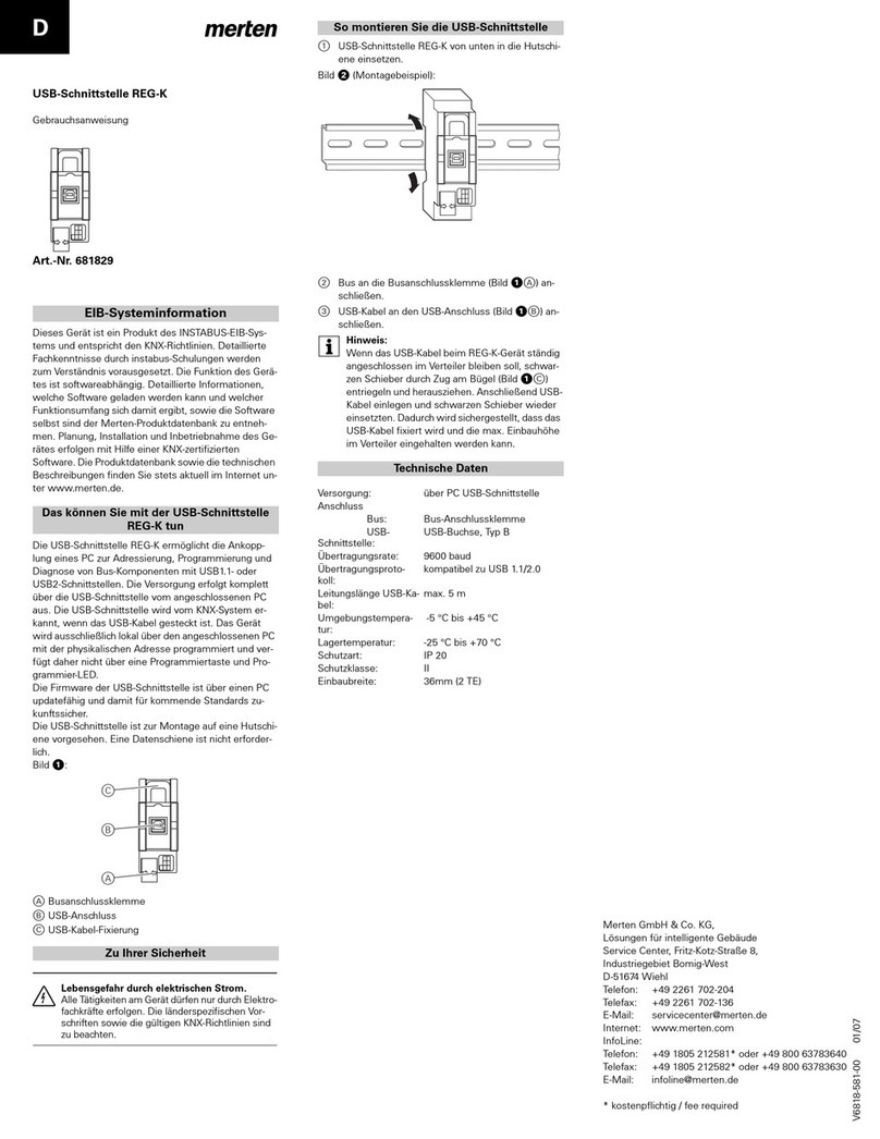
merten 681799 User manual

D
Die USB-Schnittstelle UP ermöglicht die Ankopplung ei-
nes PC zur Adressierung, Programmierung und Diagno-
se von KNX-Komponenten mit USB1.1- oder USB2-
Schnittstellen.
Das Gerät verfügt über einen integrierten Busankoppler
und wird über eine Busanschlussklemme mit dem Bus
verbunden.
Die Versorgung erfolgt komplett über die USB-Schnitt-
stelle vom angeschlossenen PC aus. Die USB-Schnitt-
stelle wird vom KNX-System erkannt, wenn das USB-
Kabel gesteckt ist. Das Gerät wird ausschließlich lokal
über den angeschlossenen PC mit der physikalischen
Adresse programmiert und verfügt daher nicht über
eine Programmiertaste und Programmier-LED.
Die Firmware der USB-Schnittstelle ist über einen PC
updatefähig und damit für kommende Standards zu-
kunftssicher.
Die USB-Schnittstelle ist für die Schraubmontage in ei-
ner 60er-Installationsdose vorgesehen.
Zu komplettieren mit der Zentralplatte für Fernmelde-
Anschlussdose TAE (z. B. Art.-Nr. 2960.., 2979.., 2978..,
2928.., 2938..).
|Gemeinsame Abdeckungen für Geräte mit 230 V
und Geräte mit Kleinspannung sind für UP-Schal-
tern und Steckdosen mit schraubenlosen Klem-
men zulässig. Beachten Sie die entsprechenden
Vorschriften.
Das können Sie mit der USB-Schnittstelle UP
tun
¼
Lebensgefahr durch elektrischen Strom.
Alle Tätigkeiten am Gerät dürfen nur durch Elektro-
fachkräfte erfolgen. Die länderspezifischen Vor-
schriften sowie die gültigen KNX-Richtlinien sind
zu beachten.
1Busanschlussklemme an der Rückseite der USB-
Schnittstelle anschließen (Bild !B).
2USB-Schnittstelle in eine mindestens 20 mm tiefe
Unterputzdose montieren.
3Die Öffnungen der TAE-Abdeckung ausbrechen.
4Die TAE Abdeckung auf die USB-Schnittstelle
schrauben.
5USB-Kabel an den USB-Anschluss (Bild !A) an-
schließen.
Bild !:
AUSB-Anschluss
BBusanschlussklemme
Zu Ihrer Sicherheit
So montieren Sie die USB-Schnittstelle
Technische Daten
Versorgung: über PC USB-Schnittstelle
Anschluss
Bus: Busanschlussklemme
USB-Schnittstelle: USB-Buchse, Typ B
Übertragungsrate: 9600 baud
Übertragungsprotokoll: kompatibel zu USB 1.1/2.0
Leitungslänge
USB-Kabel: max. 5 m
Umgebungstemperatur: -5 °C bis +45 °C
Lagertemperatur: -25 °C bis +70 °C
Schutzart: IP 20
Schutzklasse: II
Einbaubreite: 36mm (2 TE)
A
B
Merten GmbH & Co. KG,
Lösungen für intelligente Gebäude
Service Center, Fritz-Kotz-Straße 8,
Industriegebiet Bomig-West
D-51674 Wiehl
Telefon: +49 2261 702-204
Telefax: +49 2261 702-136
E-Mail: [email protected]
Internet: www.merten.de
InfoLine:
Telefon: +49 1805 212581* oder +49 800 63783640
Telefax: +49 1805 212582* oder +49 800 63783630
E-Mail: [email protected]e
* kostenpflichtig / fee required
USB-Schnittstelle UP
Gebrauchsanweisung
Art.-Nr. 681799
V6817-581-00 06/07

GB
The USB interface, flush-mounted allows linking to a PC
for addressing, programming and diagnosis of KNX
components with USB1.1 or USB2 interfaces.
The device has an integrated bus coupler and is
connected to the bus with a bus connecting terminal.
Power is supplied entirely from the connected PC via
the USB interface. The USB interface is recognised by
the KNX system when the USB cable is plugged in. The
device is programmed with the physical address locally
only via the connected PC and therefore does not have
a programming button or a programming LED.
The firmware for the USB interface can be updated via
a PC and is therefore future-proof for any later
standards.
The USB interface is provided for screw assembly in a
size 60 installation box.
For combination with the central plate for telephone
socket-outlet TAE (e.g. Art. no. 2960.., 2979.., 2978..,
2928.., 2938..).
|Common covers for 230 V devices and low-
voltage devices are allowed for flush-mounted
switches and socket-outlets with screwless
terminals. Observe the relevant regulations.
What you can do with the USB interface,
flush-mounted
¼
Risk of fatal injury from electrical current.
All work carried out on the device may only be
performed by skilled electricians. The country-
specific regulations and the valid KNX guidelines
must be followed.
1Connect bus connecting terminal on the back of
the USB interface (figure !B).
2Install the USB interface in a flush-mounted box at
least 20 mm deep.
3Break open the openings of the TAE cover.
4Screw the TAE cover onto the USB interface.
5Connect the USB cable to the USB connection
(figure !A).
Figure !:
AUSB connection
BBus connecting terminal
For your safety
How to install the USB interface
Te c h n i c a l d a t a
Power supply: via PC USB interface
Connection
Bus: Bus connecting terminal
USB interface: USB socket, type B
Transmission rate: 9600 baud
Transmission log: compatible with USB 1.1/
2.0
Cable length USB cable: max. 5 m
Ambient temperature: -5 °C to +45 °C
Storage temperature: -25°C to +70°C
Type of protection: IP 20
Protection class: II
Mounting width: 36 mm (2 modules)
A
B
Merten GmbH & Co. KG,
Solutions for intelligent buildings
Service Center, Fritz-Kotz-Straße 8,
Industriegebiet Bomig-West
D-51674 Wiehl
Phone: +49 2261 702-204
Fax: +49 2261 702-136
E-Mail: [email protected]
Internet: www.merten.de
InfoLine:
Phone: +49 1805 212581* or +49 800 63783640
Fax: +49 1805 212582* or +49 800 63783630
E-Mail: [email protected]e
* fee required
USB interface, flush-mounted
Operating instructions
Art. no. 681799
Table of contents
Languages:
Other merten USB Interface manuals
Popular USB Interface manuals by other brands
Thorsis Technologies
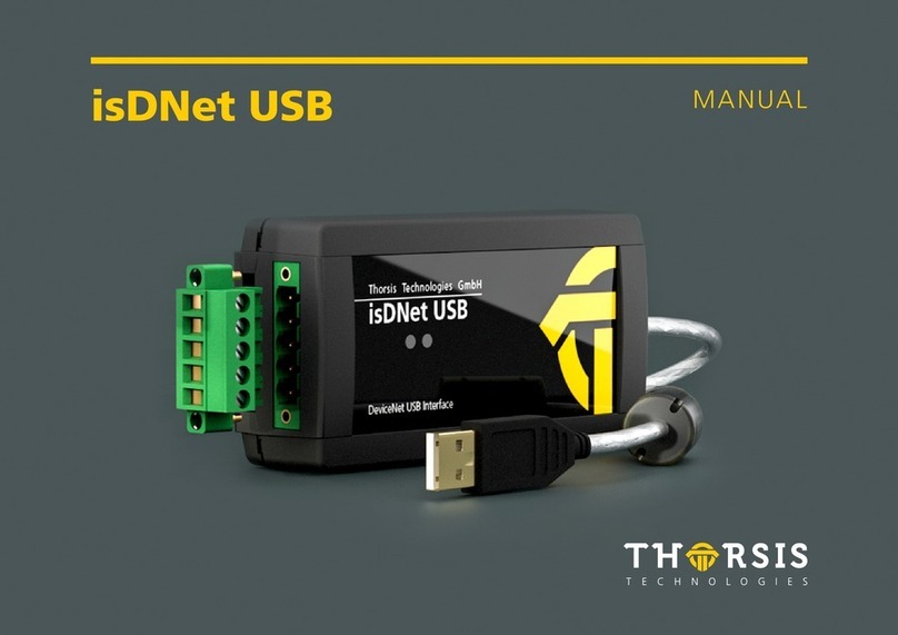
Thorsis Technologies isDNet USB manual
Analog Devices
Analog Devices Dust Networks DC9006A user guide
ESD electronic
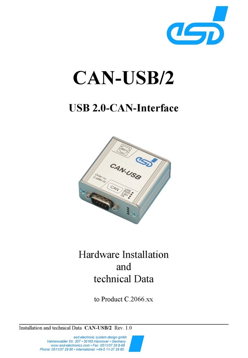
ESD electronic CAN-USB/2 Hardware installation and technical data

Midnight Design Solutions
Midnight Design Solutions NUE-USB Card Operator's manual
OHAUS
OHAUS Ranger 3000 Series instruction manual
ISSC
ISSC BM77EVB user guide
