©2001 Xantrex Technology Inc.
P/N 975-0027-01-01 Rev A 09/01
TT
TT
Table of Cable of C
able of Cable of C
able of Contentsontents
ontentsontents
ontents
1.0 INTRODUCTION1.0 INTRODUCTION
1.0 INTRODUCTION1.0 INTRODUCTION
1.0 INTRODUCTION ..............................................................................................................................................
..............................................................................................................................................
.......................................................................11
11
1
Unpacking and Inspection ...................................................................................1
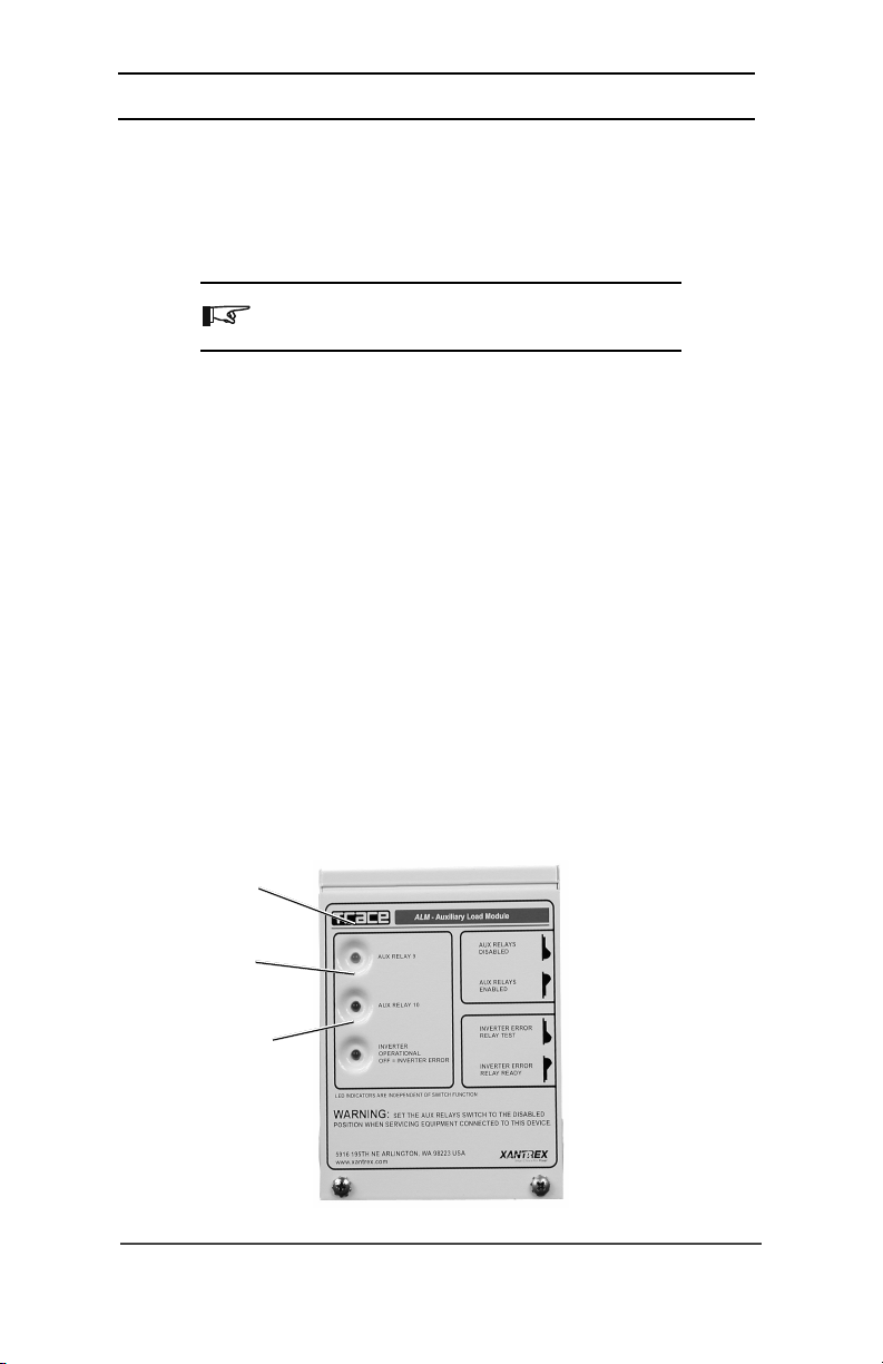
Controls and Indicators ........................................................................................2
Indicator LEDs .................................................................................................. 2
AUX RELAY 9 LED ........................................................................................ 2
AUX RELAY 10 LED ...................................................................................... 2
INVERTER OPERATIONAL LED..................................................................2
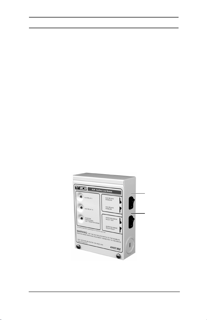
Switches ............................................................................................................3
AUX RELAY Switch ....................................................................................... 3
INVERTER ERROR Switch ...........................................................................3
Internal Components ............................................................................................4
Relays ....................................................................................................................4
Relay Connections.................................................................................................4
Relay Terminal Block ....................................................................................4
Ground Stud.................................................................................................5
Fuses ..................................................................................................................... 5
2.0 INST2.0 INST
2.0 INST2.0 INST
2.0 INSTALLAALLA
ALLAALLA
ALLATIONTION
TIONTION
TION ....................................................................................................................................................
....................................................................................................................................................
..........................................................................77
77
7
Tools Required ......................................................................................................7
Pre-Installation ......................................................................................................7
Mounting ............................................................................................................... 8
Wiring ..................................................................................................................10
Terminal Block Wiring ....................................................................................10
RY 11 Error Indicator Wiring ..............................................................................11
Communication Cable ........................................................................................ 12
Internal Sticker ....................................................................................................13
3.0 OPERA3.0 OPERA
3.0 OPERA3.0 OPERA
3.0 OPERATIONTION
TIONTION
TION ........................................................................................................................................................
........................................................................................................................................................
............................................................................ 1515
1515
15
Test Procedures ...................................................................................................15
Operation ............................................................................................................16
Active-High Type Relay ................................................................................... 16
Active-Low Type Relay ....................................................................................16
ALM Applications ...............................................................................................16
Active-High Configurations ................................................................................17
High-Voltage Alarm ........................................................................................17
Battery Exhaust Fan Controller ......................................................................17
Exhaust Fan Electrical Wiring .........................................................................18
Simple Charge Controllers .............................................................................18
Photovoltaic Charge Controller .................................................................18
Over-Voltage Protection Using a Grid-Tie Inverter ...................................19
Active-Low Configurations..................................................................................20
DC Load Controller .........................................................................................20
Load Diversion Controller .............................................................................. 20
Low-Voltage Alarm ......................................................................................... 21
i