Mesh S618 User manual


Table of Contents
1. Warnings & Suggestions 4
a. Safety warnings
b. Electrical safety information
c. FCC compliance
2. Part Number Decoder 7
3. Node Components 9
a. S618 node box
b. Solar panel box
4. Preparation 11
a. Unboxing the S618 node
b. Unboxing the solar panel
c. Overview of node ports
d. Overview of USB Hub ports
e. Node modes
5. Creating Your Network 16
a. Setting up the mobile app
b. Getting started
c. Adding to your network
6. Installing the Mount 23
a. Installation factors
b. Mount installation
7. Installing the Node 24
a. Placing a node in its mount
b. Using a node in Gateway Mode
1

8. Installing the Solar Panel 28
a. Preparing to install
b. Attaching onto the mount
9. Servicing the Node 31
a. Outer case removal
b. Upgrading node firmware
10. Configurations 34
a. Cellular: SIM card installation
b. Secondary panel installation
c. Power over Ethernet (PoE)
d. Extended range: antenna installation
11. Troubleshooting 38
a. Debugging your node
b. Mobile app diagnostics
c. Common issues
12. Warranty 50
13. Return Policy 50
2

Trademarks
MeshPlusPlus, Mesh++, the Mesh++ logo, and S618™ are all
trademarks of MeshPlusPlus, Inc.
Copyrights
Copyright © 2022 MeshPlusPlus, Inc. All rights reserved. No part of
this publication may be reproduced or distributed in any form or
by any means, or stored in a database or retrieval system, without
the prior written consent of MeshPlusPlus, Inc.
Disclaimers
The information contained in this document is subject to change
without notice. Mesh++ assumes no responsibility for any errors
that may appear. Mesh++ makes no warranties, expressed or
implied, by operation of law or otherwise, relating to this
document or products described herein.
Scan this
QR code to
watch a
video
tutorial of
installation.
3

1. Warnings & Suggestions
An S618 is powered primarily via solar energy. If you would like to
power it alternatively through USB-C charging, a required USB-C
Power Delivery 3.0 adapter is not included. When sourcing one,
please note that the adapter must be rated for at least 60W of
output power (20V, 3A minimum) to properly charge the S618.
The S618 can also be powered via DC power supply (12V, >6A) or
802.3af/at Power over Ethernet (PoE) if installed as an add-on.
a. Safety warnings
i. An S618 Installation site typically consists of a high
supporting structure such as a mast, tower or building for
the S618. To prevent injury or loss of life, please take extreme
care when working at heights or near power lines.
ii. Grounding and protective earth:
1. The S618 assembly must be properly grounded through
the mount to protect against lightning. It is the user’s
responsibility to install the equipment in accordance with
national regulations.
2. In the USA, follow Section 810 of the National Electric
Code, ANSI/NFPA No.70-1984 (USA). In Canada, follow
Section 54 of the Canadian Electrical Code. These codes
describe correct installation procedures for grounding the
outdoor unit, mast, lead-in wire and discharge unit, size of
grounding conductors and connection requirements for
grounding electrodes. Other regulations may apply in
different countries and therefore it is recommended that
installation be contracted to a professional installer.
iii. Before servicing the equipment, always power down and
remove it from its installation site.
iv. External cables:
1. Safety may be compromised if outdoor rated cables are
not used for connections that will be exposed to the
outdoor environment. Connections intended to be
4

permanent should be sealed with caulking appropriate
for the environment.
v. Ultimate disposal of this product should be handled
according to all national laws and regulations.
vi. To prevent the system from overheating, do not operate it in
an area that exceeds the maximum recommended ambient
temperature of: 104°F (40°C).
vii. IEC 60950-1 - information technology equipment. No
components failed during any safety test.
b. Electrical safety information
i. Installation of the S618 must comply with local and national
electrical codes.
ii. Compliance is required with respect to voltage, frequency,
and current requirements indicated on the manufacturer’s
label. Connection to a different power source than those
specified may result in improper operation, damage to the
equipment or cause a fire if limitations are not followed.
iii. There are no operator serviceable parts inside this
equipment. Service should be provided only by Mesh++ or
authorized reseller.
c. FCC compliance
i. Changes or modifications not expressly approved by the
party responsible for compliance could void the user’s
authority to operate the equipment.
ii. This device complies with Part 15 of the FCC Rules. Operation
is subject to the following two conditions:
1. This device may not cause harmful interference.
2. This device must accept any interference received,
including one that may cause undesired operation.
iii. This equipment generates, uses, and can radiate radio
frequency energy and, if not installed and used in
accordance with the instruction manual, may cause harmful
interference to radio communications. Operations of this
equipment in a residential area is likely to cause harmful
interference to other WiFi equipment in which the user will
be required to correct the interference at their own expense.
5

iv. Class A Notice for FCC
1. Modifying the equipment without the authorization of
Mesh++ may result in the equipment no longer
complying with FCC requirements for Class A digital
devices. In that event, your right to use the equipment
may be limited by FCC regulations, and you may be
required to correct any interference to radio or television
communications at your own expense.
2. This equipment has been tested and found to comply
with the limits for a Class A digital device, pursuant to Part
15 of the FCC Rules. These limits are designed to provide
reasonable protection against harmful interference when
the equipment is operated in a commercial environment.
This equipment generates, uses, and can radiate radio
frequency energy and, if not installed and used in
accordance with the instruction manual, may cause
harmful interference to radio communications. Operation
of this equipment in a residential area is likely to cause
harmful interference in which case users will be required
to correct the interference at their own expense.
v. Class A Notice for Canada: this digital apparatus complies
with Canadian ICES-003.
vi. Read, follow, and keep these instructions.
vii. Heed all warnings.
viii. Only use attachments/accessories specified by the
manufacturer.
ix. WARNING: Do not use this product in a location that can be
submerged by water.
6

2. Part Number Decoder
The S618’s extended part number may be helpful to reference if its
configuration needs to be verified before troubleshooting. This
number can be found on a label on the outer case of the node.
1. Model Number: S618
2. Version Number: 1 (as of January 1, 2023)
3. Hardware Revision:
a. 04: standard S618
b. 05: S618 with N-type connectors for external antennas
(additional WiFi 6E radio is required to use them, but the
node can still operate normally without it)
c. 05E: same as above; the connectors are routed to replace
the integrated 2x2 WiFi 6 antennas with external ones
4. Battery Pack(s): 1-5
5. Power over Ethernet (PoE) Capability:
a. Active (A): an active PoE injector (PSE) can power devices
through the USB-C port on the node
b. Passive (P): a passive PoE injector (PSE) can power 12V or
24V devices through the USB-C port on the node
c. Power Module (D): a Powered Device module that allows
the node to be powered or slowly charged over PoE
d. None (N): the node cannot be powered or power other
devices through PoE
7

6. Cellular Antennas:
a. C2: 2 antennas installed - 2x2 EM06 4G LTE modem
b. C4: 4 antennas installed - 4x4 EM160 4G LTE or 5G
sub-6 GHz modems
7. Speciality Features:
a. GPS (G): a module that allows the node to determine its
position to an accuracy of several meters
b. eMMC size (2, 5-8): embedded, permanent memory
soldered in a node with its size based on the specific
exponent of the base number 2 (i.e. 5 = 2^5 = 32 GB)
c. Accelerometer (A): a preinstalled integrated circuit that
measures accelerations in 3 directions and rotation along 3
axes - this can determine if a node is moving, which
orientation it is facing with respect to ground, and wind
forces on the mounting structure
d. TPM (T): a Trusted Platform Module allows the node to
securely boot with a cryptographically secure key, keeping
the firmware from being copied
e. eSIM (S): an electronic SIM is a preinstalled integrated circuit
that is equivalent to a SIM card, but can be reprogrammed
to work with various providers without physically switching
out a SIM card
f. External radio: chip ID + frequency band (i.e. 9746 for
QCN9074 @ 6 GHz)
8. Solar Panel Wattage:
a. S75: 75W
b. S83: 83W
9. Cellular Modem:
a. L06: EM06 4G LTE CAT 6 modem
b. L16: EM16 4G LTE CAT 16 modem
c. L5G: 5G-LR sub-6 GHz modem
10. microSD Capacity (M6-9): additional microSD card included for
storage with its size based on the specific exponent of the base
number 2 (i.e. 7 = 2^7 = 128 GB)
8
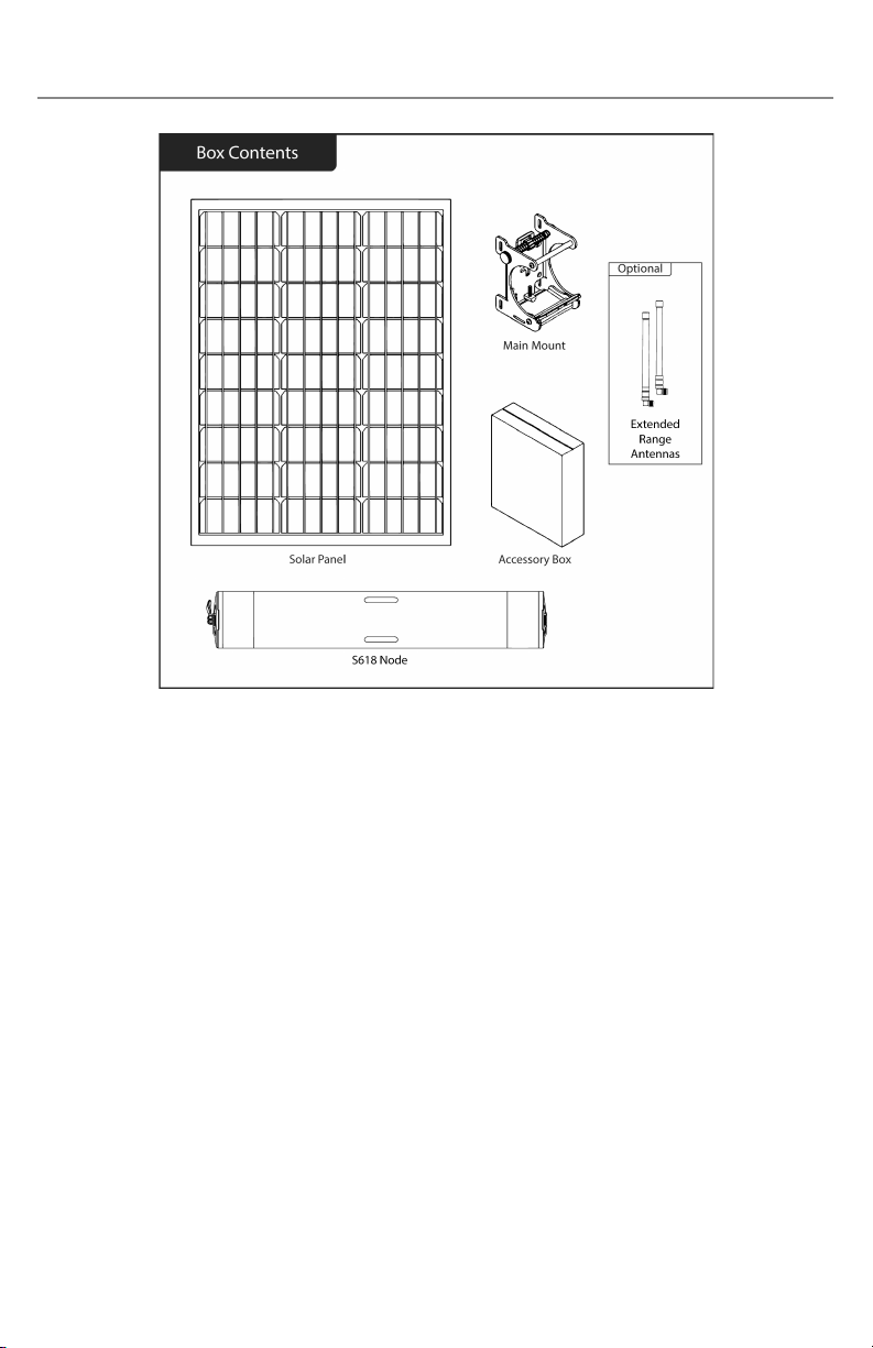
3. Node Components
a. S618 node box
i. S618 Node Assembly
1. Node (cylinder) containing mesh radio and antennas
ii. Main Mount
1. Mount that affixes the cylinder and solar panel onto a
pole or wall
iii. Accessory Box
1. USB Hub
2. SAE cable
3. USB-C data transfer cable
4. Hex Key
5. Hose Clamps
iv. Extended range (N-type) antennas (optional)
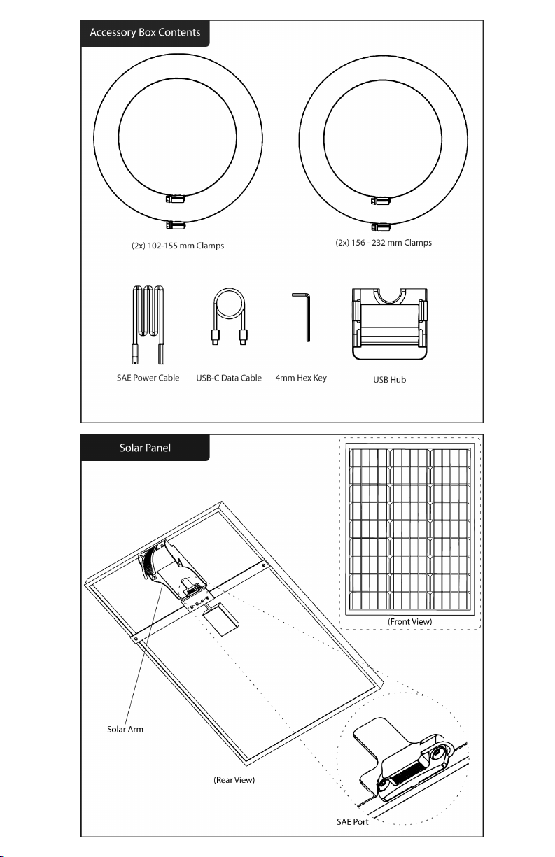
b. Solar panel box
i. Solar Panel(s) - 1 or 2 per box
1. Solar panel with arm for mounting
9
10
4. Preparation
a. Unboxing the S618 node
i. Open the node box and the smaller accessory box inside of
it, verifying that all items in the prior section were included.
ii. Slide the S618 out of the box and remove the 2 cardboard
endcaps on either side of the node; keep them with the box
in case the node needs to be repackaged.
iii. With the silver clamp knob on the mount facing up, use your
fingers or the 4 mm hex key to unscrew the knob until the
node can be removed from the mount - it can be slid out
from the side if necessary.
iv. Note the node’s MAC address printed on the label affixed to
the outer case - verify that it contains the same MAC address
as the one printed on the side of the node box.
b. Unboxing the solar panel
i. Open the solar panel box, slide the panel(s) out from the
side, and remove the 2 cardboard endcaps.
ii. Remove any other cardboard corners from the panel(s) if any
are present. Obstructions to the panels’ solar cells will affect
its ability to charge .
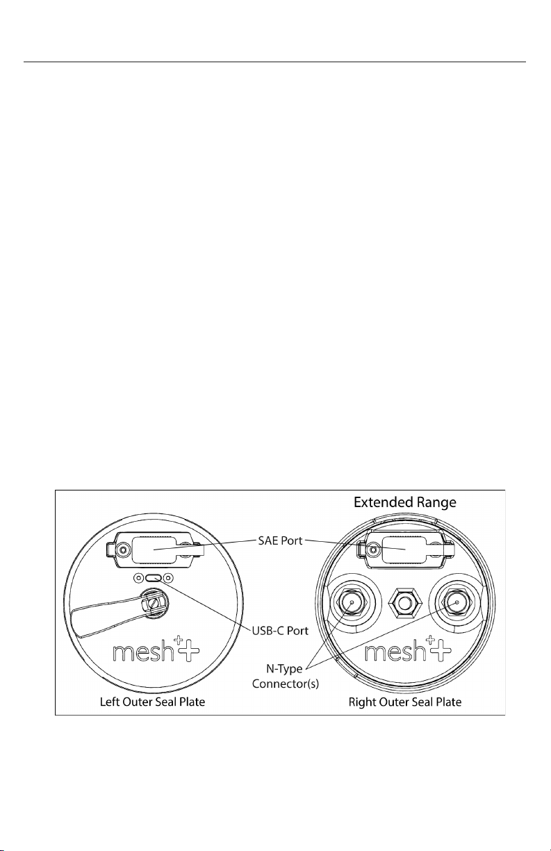
c. Overview of node ports
i. USB-C port
1. The S618 has a USB-C port near the cam handle that
connects the node to the USB Hub for data transfer, but
11
may also be used to charge the node directly via USB-C
Power Delivery.
2. If you plan to power or charge your node via USB-C Power
Delivery, the USB-C PD adapter must be rated for 60W or
more of output power (20V, 3A minimum) to function.
ii. SAE ports
1. The S618 has 2 SAE ports located on each end of the
device. Using the SAE to SAE cable, you may connect a
solar panel to the node to power it. A single solar panel
can be connected to either port, or 2 panels can be
connected concurrently. Please note that SAE cables
provided by Mesh++ have a specific polarity that may not
be the same as 3rd-party cables. Using other cables may
cause damage to the node.
2. SAE cables may be used together if a second solar panel is
installed further away. Chaining more than 5 SAE cables
between the node and panel may impact efficiency.
3. You may also power the node via power adapter through
the SAE port by using an SAE to barrel jack connector.
This requires a DC power supply (12V, >6A).
iii. N-type connectors
1. The S618 may have 4 N-type connectors for external
antennas, which can be used with a WiFi 6E radio, or to
replace the integrated 2x2 WiFi 6 antennas.
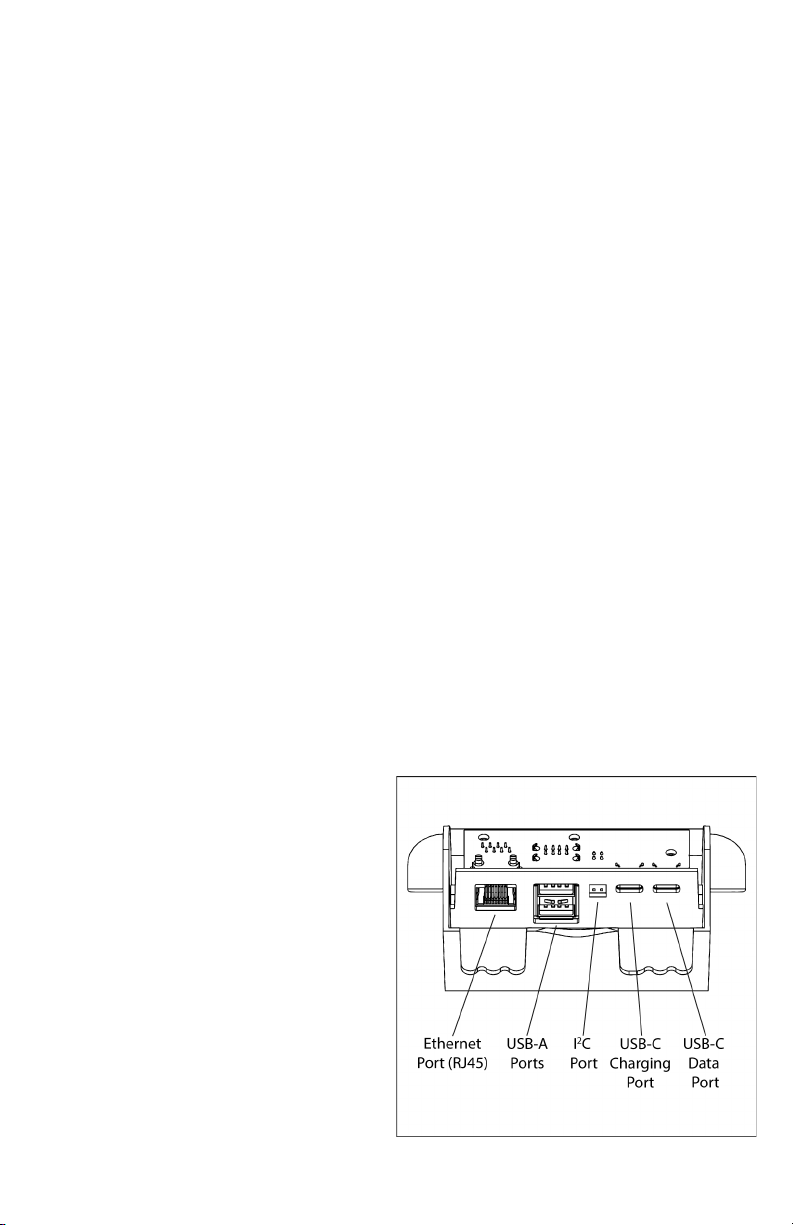
d. Overview of USB Hub ports
i. The USB Hub has 5
different types of ports:
1. USB-C for data transfer
to the node
2. USB-C for charging
3. I ²C port for peripheral
sensors
4. 2 USB-A ports
5. Ethernet port (RJ45)
for network
connectivity
12
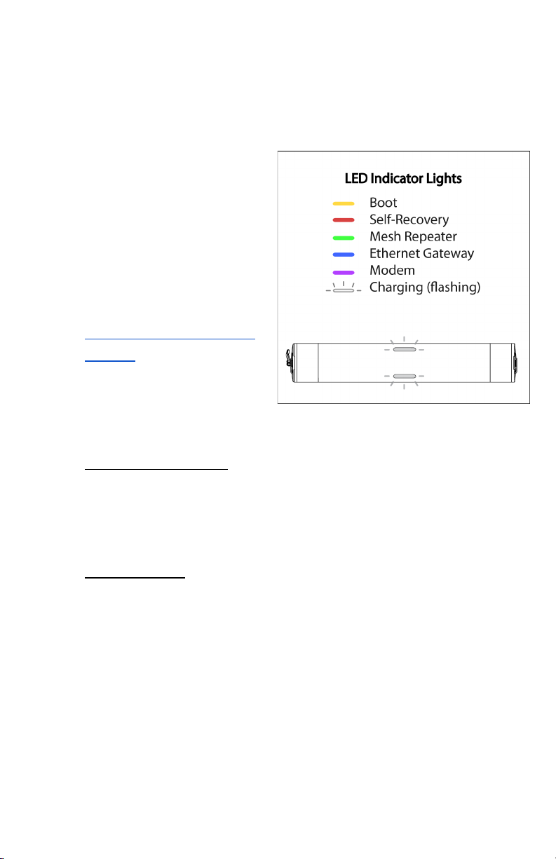
e. Node modes
i. The S618 has a number of autoconfigured modes that
determine its specific function within a mesh network. Each
mode is identified by LED indicators located on the 2 LED
windows on the node’s outer case.
1. LED indicators may
take up to 5 minutes
to update their
current mode status.
2. If you are having
trouble reaching a
certain mode, please
visit the specific Issue
# listed below in
section 11.c - Common
Issues.
ii. The following LED
indicators correlate with
each node mode:
1. Yellow: Boot Mode - less than 1 minute
Boot Mode indicates that the node is entering its booting
sequence and will briefly enter this mode after being
powered on - Issue #2.
2. Offline Mode - consistent indicator
Offline Mode is disabled by default and can be toggled on
through the web dashboard. This mode allows the
network to stay up for internal network access in case of
an external outage. If connectivity is lost, the LED
indicators will turn yellow, meaning the network is offline
but still able to communicate internally (bridged). The
lights will return to their original mode once the internet
is restored.
13

3. Red: Self-Recovery Mode
Self-Recovery mode indicates that the node is powered
on and has successfully booted, but an internet
connection has not been established. This mode should
only occur briefly until the node enters Gateway, Repeater,
or Modem Mode. Occasionally, the device may enter
Self-Recovery mode when transitioning between other
modes - Issue #3.
4. Blue: Gateway Mode
Gateway Mode indicates that the node has successfully
connected to the internet and is acting as the connection
between the mesh network and the internet. This mode
can be achieved by connecting the node to a router via
USB Hub - Issue #7. The ethernet connection must have
unrestricted access to the internet, which should work
with any standard ethernet connection through a router .
If you would like to learn more about the specific
requirements, please visit section 11.c - Common Issues .
5. Green: Repeater Mode
Repeater Mode indicates that the node has successfully
meshed with another online node, thus creating a mesh
network. This mode can only be achieved when a node in
Gateway Mode is present in the mesh and the specific
node is within range of it or another node in Repeater
Mode - Issue #8.
6. Purple: Modem Mode
Modem Mode indicates that the node has been
successfully connected to a cellular network. Similar to
Gateway Mode, it can now serve as a main access point in
a mesh network - Issue #10.
14

This mode can only be achieved on cellular-enabled
nodes - to learn how to install a SIM card into your node,
please visit section 10.a - Cellular: SIM Card Installation.
7. Blinking (any color)
Blinking LEDs indicate that the node is charging its
battery through a source of power. The LEDs blink at a
rate corresponding to the speed of charge: fast blinking
indicates a fast charge and slow blinking indicates a
slower charge. Charge speed reduces when the state of
charge is under 15% or over 90% capacity to preserve
battery health - Issues #4-6.
A mesh network is a self-forming WiFi network where a group
of devices repeat the signal of an internet source to expand its
connection. When deployed together in the same network,
S618 nodes form a mesh network. This requires at least 1 node
to have a stable internet connection in either Ethernet Gateway
or Modem Mode, with the rest in Repeater Mode to extend the
network’s connectivity.
15

5. Creating Your Network
a. Setting up the mobile app
i. Search for “Mesh++” on the iOS App Store or Google Play
Store and install the Mesh++ mobile app. Please ensure that
the app is kept up to date as we continue to add new
features and enhancements.
ii. Register for a free account by entering your company name
and email. You should then receive an email from
[email protected] to activate your account. If you
have not received one, it may be in the Spam folder.
From your web or phone browser, create your username
with your registered email and a selected password. Use this
information to log back into the mobile app to begin.
b. Getting started
i. Once you have successfully logged into the mobile app, you
will be taken to the Dashboard tab, which shows a list of
networks created on this account along with their statuses.
Once completely loaded, all nodes in every network created
by this account can be searched for
via Bluetooth in the Search tab, or
can be accessed within its network.
ii. The Networks navigation bar
contains 4 useful buttons:
1. Search for networks by name
2. Sort the network list
3. Enable mobile notifications for
each network when certain
connectivity statuses change
4. Refresh all networks, which
directly affects each node's
displayed status
iii. Navigate to the Setup tab at the
bottom of the screen. Here, you are
able to set up a new network or
node to use.
16
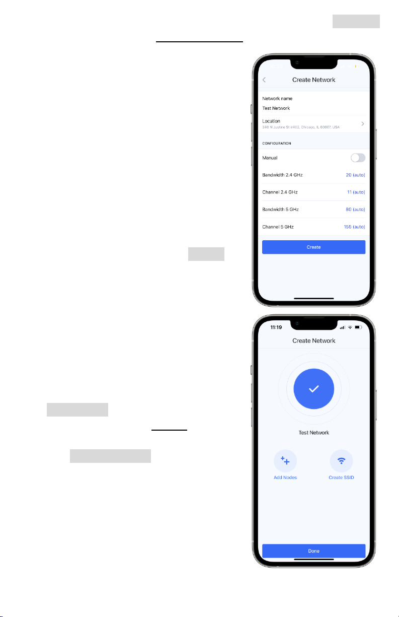
iv. If you do not have a network set up already, tap the Network
button to enter the Create Network page.
1. Network name: what your
network will be called in the app.
Name it something you will
remember. This differs from any
SSID name that will be
broadcasted.
2. Location: choose the general
location of your network.
3. Configuration: you may choose
certain channel and bandwidth
settings here manually, but we
recommend leaving it set to its
default autoconfigure setting.
v. Once completed, tap the Create
button to make your network.
c. Adding to your network
i. You may now either add nodes to
the network or create an SSID for
users to connect to the network.
Both must be done (in any order)
to create a working mesh network.
ii. If your network does not already
have nodes added to it, tap the
Add Nodes button. The app will
redirect you to the Nodes tab in
your newly created network.
iii. Tap Add new node to begin
registering a new node to your
network - we recommend using
Bluetooth initially to search for
local nodes.
1. Move from existing network: if a
node is already on a network,
you may move it to your newly
created one
17
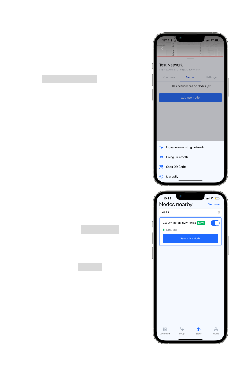
2. Using Bluetooth: use your mobile device to scan for local
nodes via Bluetooth
3. Scan QR Code: scan the QR
code on a node’s serial number
sticker located on its case
4. Manually: add the node’s MAC
address by typing it into the app
iv. Tap Using Bluetooth - if you are
within 10 m (30 ft) of the node, the
MAC address found on its case
should appear on your search.
Move as close as possible to the
node to connect to it via Bluetooth
on your mobile device.
1. If you are near many nodes, use
the search bar and type part of
the MAC address to limit the
number of nodes that are found.
2. Once successfully connected, an
on/off toggle button will appear.
The node may be switched on
or off during the setup process.
3. On the top right of the screen,
you may tap Disconnect to force
a disconnection and stop
interacting with the node. If you
do not see your node, you may
need to tap Repeat multiple
times until it appears. If you
cannot find your node or its
MAC is located under “Other
Networks,” please see issue # 1
in section 11.c - Common Issues
for additional guidance
18
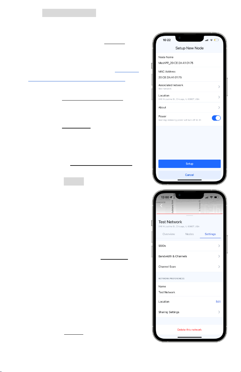
v. Tap Setup this Node to navigate to the node’s main options
list. Here, you are able to change its name, view its MAC
address , power status, add it to a
network, and view the About page
for additional information about
the node, such as diagnostics and
Bluetooth firmware - visit section
11.b - Mobile App Diagnostics , for a
guide of this page.
1. On the Associate network page,
add your node to your newly
created network.
2. On the Location page, add the
location that the node will be at.
This does not have to be entirely
accurate, but can help when
using the Network Overview tab
or dashboard site.
3. Tap the Setup button and the
app will confirm with a message
that the node was successfully
adopted to the network.
4. You will then be able to return
to the network or add more
nodes directly from there.
vi. Return to your newly created
network and visit the Settings tab.
Here, you are able to create Service
Set IDs (SSIDs) for users to connect
their devices to,, change the
network’s bandwidth or channels,
change its display name on the
app, change its general location,
and sharing settings.
vii. Under the SSIDs page, you will find
various settings to create a usable
SSID for your network.
19
Table of contents
Popular Inverter manuals by other brands


Sinee
Sinee EM760 Series user guide

Vicruns
Vicruns VD500 Series instruction manual

Mitsubishi Electric
Mitsubishi Electric 800 Series instruction manual

Mitsubishi Electric
Mitsubishi Electric FR-E540 instruction manual

Hensel
Hensel Pro Mini 1200AS user manual

Q3 ENERGIE
Q3 ENERGIE QX3 Series Installation and operating instructions

SEW-Eurodrive
SEW-Eurodrive MOVITRAC advanced Compact operating instructions

Clarke
Clarke CI-200 Operation and maintenance instructions

AIMS
AIMS BCT010009D instruction manual

DUROMAX
DUROMAX XP2000iS Operator's manual

BYD
BYD Premium LVS 4.0 operating manual

DAB PUMPS LTD.
DAB PUMPS LTD. SUNDRIVER quick guide