BYD Premium LVS 4.0 User manual

Be Connect
GET IT ON
Google play
Download on the
App Store
BYD Battery-Box Premium
Operating Manual
LVS 4.0,8.0,12.0,16.0,20.0,24.0
BYD Europe B.V.
V1.0

1
Legal Provisions
All the information in this document is the property of BYD Europe B.V. No part of this document
could be reproduced in any way for business use. Internal use is allowed.
BYD Europe B.V. makes no representations or warranties express or implied, with respect to this
document or any of the equipment and/or software it may describe, including (with no limitation) any
implied warranties of utility, merchantability, or fitness for any particular purpose. All such
representations or warranties are expressly disclaimed. Neither BYD Europe B.V. nor its distributors
or dealers shall be liable for any indirect, incidental, or consequential damages under any
circumstances.
The exclusion of implied warranties may not apply in all cases under some statutes, and thus the
above exclusion may not apply.
This document does not replace and is not intended to replace any local, state, provincial, federal, or
national laws, regulations, or codes applicable to the installation, electrical safety, and use of the
battery system. BYD Europe B.V. assumes no responsibility for the compliance or noncompliance
with such laws or codes in connection with the installation of the battery system.
Specifications are subject to change without notice. Every effort has been made to make this
document complete, accurate, and up-to-date. However, BYD Europe B.V. may need to make some
improvements under certain circumstances without advance notice. BYD Europe B.V. shall not be
responsible for any loss caused by this document, including, but not limited to, omissions errors,
typographical errors, arithmetical errors, or listing errors in this document.
All trademarks are recognized.
Limited Warranty
You can download the latest Limited Warranty from the Internet at www.bydbatterybox.com.
BYD Europe B.V.
‘s-Gravelandseweg 256, 3125 BK, Schiedam, the Netherlands

Content
Legal Provisions ...............................................................................................................................1
1. Information on this Document ....................................................................................................4
1.1. Validity .............................................................................................................................4
1.2. Target Group ...................................................................................................................4
1.3. Content and Structure of this Document ..........................................................................4
1.4. Declaration of Conformity.................................................................................................4
1.5. Levels of Warning Messages ...........................................................................................4
1.6. Symbols in the Document ................................................................................................5
1.7. Designation in the Document ...........................................................................................5
2. Safety ........................................................................................................................................6
2.1. Intended Use ...................................................................................................................6
2.2. IMPORTANT SAFETY INSTRUCTIONS .........................................................................6
2.2.1. Battery Module Leakage ........................................................................................6
2.2.2. Firefighting Measures ............................................................................................6
2.2.3. Battery Modules Handling and Storage Guide .......................................................7
2.2.4. Warning of Overvoltages .......................................................................................7
2.2.5. Caution of Weight ..................................................................................................8
2.2.6. Notice of Property Damage....................................................................................8
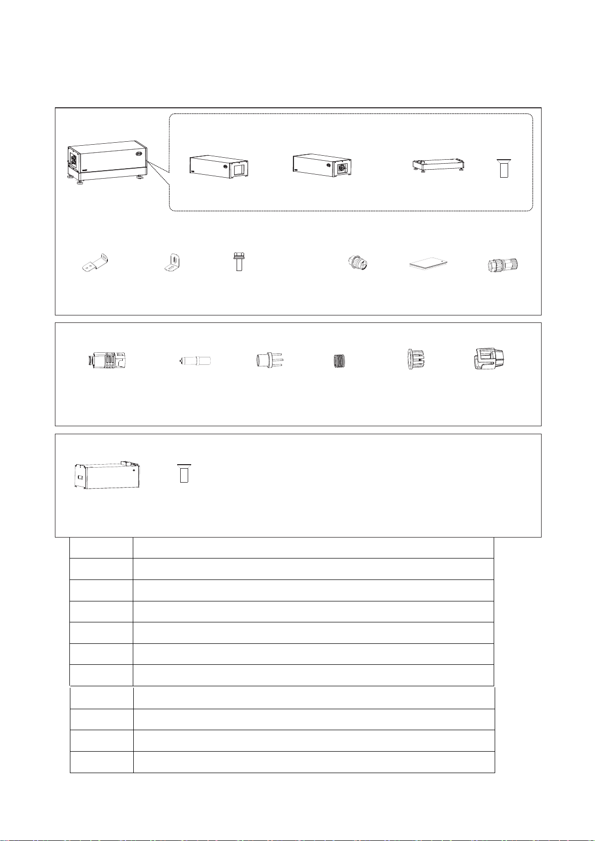
3. Scope of Delivery.......................................................................................................................9
4. Battery System Overview.........................................................................................................11
4.1. Battery System Description............................................................................................11
4.2. Interface.........................................................................................................................12
4.3. Symbols on the System .................................................................................................12
4.4. LED Signals................................................................................................................... 14
5. Installation................................................................................................................................ 15
5.1. Requirements for Installation .........................................................................................15
5.1.1. Requirements for Installation Location .................................................................15
5.1.2. Tools....................................................................................................................15
5.1.3. Safety Gear .........................................................................................................15
5.1.4. Additionally Required Installation Material............................................................16
5.2. Installation......................................................................................................................16
6. Electrical Connection ...............................................................................................................19

6.1. Overview of the Connection Area...................................................................................19
6.2. Connection Diagram ......................................................................................................19
6.2.1. One Tower.................................................................................................................. 19
6.2.2. Multiple Towers ..........................................................................................................20
6.3. Connecting the PE.........................................................................................................20
6.4. Data Cable Connection..................................................................................................21
6.4.1. Data Cable Connection between Inverter and BMU.............................................21
6.4.2. Data Cable Connection between BMU and PDU .................................................23
6.4.3. Data Cable Connection between BMU and Router ..............................................23
6.4.4. Cover the Terminal Resistor ................................................................................24
6.4.5. Data Cable Connection between Towers.............................................................24
6.5. DC Connection ..............................................................................................................25
7. Commissioning ........................................................................................................................30
7.1. Switch on the Battery System ........................................................................................30
7.2. Configure the Battery System ........................................................................................31
7.3. Switch on and Commission the Inverter .........................................................................34
8. Operation.................................................................................................................................35
8.1. Switch on the Battery System ........................................................................................35
8.2. Switch off the Battery System ........................................................................................36
8.3. Maximum Current at Different Temperature...................................................................37
8.4. Protective Devices .........................................................................................................37
9. Decommissioning..................................................................................................................... 38
10. Extension ..........................................................................................................................39
11. Troubleshooting ................................................................................................................40
11.1. Battery System Behavior under Fault Conditions........................................................ 40
11.2. LED Light Designation for Errors ................................................................................40
12. Maintenance and Storage .................................................................................................42
13. Disposal of the Battery System..........................................................................................43
14. Technical Parameters .......................................................................................................44
15. Contact Information........................................................................................................... 45
Appendix Data Cable Connection Instruction with Inverters............................................................46

4
1. Information on this Document
1.1. Validity
This document is valid for the Battery-Box Premium LVS 4.0, 8.0, 12.0, 16.0, 20.0, 24.0.
1.2. Target Group
The instructions in this document may only be performed by qualified persons who must have the
following skills:
•Knowledge of how batteries work and are operated
•Knowledge of how an inverter works and is operated
•Knowledge of, and adherence to the locally applicable connection requirements, standards, and
directives
•Knowledge of, and adherence to this document and the associated system documentation,
including all safety instructions
•Training in dealing with the hazards associated with the installation and operation of electrical
equipment and batteries
•Training in the installation and commissioning of electrical equipment
Failure to do so will make any manufacturer's warranty, guarantee or liability null, and void unless
you can prove that the damage was not due to non-compliance.
1.3. Content and Structure of this Document
This document contains safety information and instructions, scope of delivery, battery system
overview, installation, electrical connection, commissioning, operation, decommissioning, extension,
troubleshooting, maintenance and storage, disposal of the battery system, technical parameters and
contact information. Please finish reading this document before taking any actions on the battery
system.
1.4. Declaration of Conformity
The battery system described in this document complies with the applicable European directives.
The certificate is available in the download area at www.bydbatterybox.com.
1.5. Levels of Warning Messages
The following levels of warning messages may occur when handling the battery system.
DANGER
Indicates a hazardous situation which, if not avoided, will result in death or serious injury.
WARNING
Indicates a hazardous situation which, if not avoided, could result in death or serious injury.

5
1.6. Symbols in the Document
1.7. Designation in the Document
Designation in this document
Complete designation
Battery System
Battery-Box Premium LVS
BIC
Battery Information Collector
BMS
Battery Management System
BMU
Battery-Box Premium LV BMU(Battery
Management Unit )-IP55
BYD
BYD Europe B.V.
PDU
Power Distribute Unit
SOC
State of Charge
Sections describing activities to be performed
by qualified persons only.
CAUTION
Indicates a hazardous situation which, if not avoided, could result in minor or moderate injury.
NOTICE
Indicates a situation which, if not avoided, can result in property damage.

6
2. Safety
2.1. Intended Use
The battery system is for residential and works with a photovoltaic system. It is a 48V Li-ion battery
storage system, with the control module on itself. It could be operated in on-grid and off-grid modes
with compatible inverters.
The battery system could be connected to the Internet through network cable for maintenance and
firmware updating.
The battery system must only be used as stationary equipment.
The battery system is suitable for indoor and outdoor use under the conditions mentioned in Section
5.1.
The battery system must only be operated in connection with a compatible inverter. The list (BYD
Battery-Box Premium LVS Minimum Configuration List) of these inverters could be found at
www.bydbatterybox.com.
The battery system is not suitable for supplying life-sustaining medical devices. Please ensure that
no personal injury would lead due to the power outage of the battery system.
Alterations to the battery system, e.g., changes or modifications are not allowed unless the written
permission of BYD is achieved. Unauthorized alterations will void the guarantee and warranty claims.
BYD shall not be held liable for any damage caused by such changes.
The type label should always be attached to the battery system.
2.2. IMPORTANT SAFETY INSTRUCTIONS
The battery system has been designed and tested in accordance with international safety
requirements. However, in order to prevent personal injury and property damage and ensure
long-term operation of the battery system, please do read this section carefully and observe all safety
information at all times.
2.2.1. Battery Module Leakage
If the battery modules leak electrolytes, contact with the leaking liquid or gas should be avoided. The
electrolyte is corrosive, and the contact may cause skin irritation and chemical burns. If one is
exposed to the leaked substance, do these actions:
Inhalation: Evacuate the contaminated area, and seek medical help immediately.
Eye contact: Rinse eyes with flowing water for 15 minutes and seek medical help immediately.
Skin contact: Wash the affected area thoroughly with soap and water and seek medical help
immediately.
Ingestion: Induce vomiting and seek medical help immediately.
2.2.2. Firefighting Measures
The battery modules may catch fire when it is put into the fire. In case of a fire, please make sure that
an ABC or carbon dioxide extinguisher is nearby. Water cannot be used to extinguish the fire.
Full protective clothing and self-contained breathing apparatus are required for the firefighters to
extinguish the fire.

7
2.2.3. Battery Modules Handling and Storage Guide
•The battery modules and its components should be protected from damage when transporting and
handling.
•Do not impact, pull, drag, or step on the battery modules.
•Do not insert unrelated objects into any part of the battery modules.
•Do not throw the battery module into a fire.
•Do not soak the battery modules in water or seawater.
•Do not expose to strong oxidizers.
•Do not short circuit the battery modules.
•The battery modules cannot be stored at high temperatures (more than 50°C).
•The battery modules cannot be stored directly under the sun.
•The battery modules cannot be stored in a high humidity environment.
•Do not use the battery modules if it is defective, or appears cracked, broken or otherwise damaged,
or fails to operate.
•Do not attempt to open, disassemble, repair, tamper with, or modify the battery modules. The
battery modules are not user-serviceable.
•Do not use cleaning solvents to clean the battery modules.
2.2.4. Warning of Overvoltages
DANGER
Danger to life due to electric shock in case of overvoltages and if surge protection is missing
Overvoltages (e.g. in the event of a flash of lightning) can be further conducted into the building and
to other connected devices in the same network via the network cables or other data cables if there
is no surge protection. Touching live parts and cables results in death or lethal injuries due to
electric shock.
•Ensure that all devices in the same network and the inverteU are integrated into the
existing surge protection.
•When laying the network cables or other data cables outdoors, it must be ensured that a
suitable surge protection device is provided at the transition point of the cable from the
EDWWHU\system or the inverter outdoors to the inside of a building.

8
2.2.5. Caution of Weight
2.2.6. Notice of Property Damage
CAUTION
Risk of injury due to weight of the battery module
Injuries may result if the battery module is lifted incorrectly or dropped while being transported
or installed.
•Transport and lift the battery module carefully. Take the weight of the battery module into
account.
•Wear suitable personal protective equipment for all work on the battery system.
NOTICE
Damage to the PDU due to sand, dust and moisture ingress
Sand, dust and moisture penetration can damage the PDU and impair its functionality.
•Only open the PDU if the humidity is within the thresholds and the environment is free of
sand and dust.
NOTICE
Damage to the battery system due to under voltages
•If the battery system doesn't start at all, please contact BYD local after-sales service
within 48 hours. Otherwise, the battery could be permanently damaged.

9
3. Scope of Delivery
A1 PDU
A2 PDU for Australia Market
B Battery module
C M4 Screw
D Hanger (PDU part)
E Hanger (Wall part)
F M5 Screw
H M6 Screw Bolt and Nut
I Documents
J Communication Gland
K DC connector
X2
KL P
M
X2 X2X2 X2
DC Connector Metal Terminal Cap
Rubber Core
X2
O
N
O-Ring Claw
Q
X1
Battery Module
C
X3
M4 Screw
A1
ED F HI
B
X2 X2 X4 X2 X1 X2
X1
Ba
Quick
tte
S
ry
tart
-Box
G
P
ui
re
de
miumL16
BYDEuropeB.V.V1.0
A2
PDU(For Australia Market)
Hanger (PDU Part) Hanger (Wall Part) M5 Screw M6 Bolt and Nut Documents
Base
J
Communication Gland
C
X2
M4 Screw
X1
PDU
++
X1
(or
X1

10
L
Metal Terminal
M
Rubber Core
N
O-ring
O
Claw
P
Cap
Q
Battery Module

11
4. Battery System Overview
4.1. Battery System Description
The Battery-Box Premium LVS is used as a connected battery for the intermediate storage of
excess PV energy in an inverter system.
It works together with Battery-Box Premium LV BMU-IP55 (BMU). The parameters and
instruction of BMU could be read on our websites. The battery system could support the backup
function of inverters and is compatible with both 1 and 3 phase inverters.
A
PDU (the normal one without the air switch, but the one for
Australia market has an air switch)
B
Battery module
C
Base
D
Button with LED
E
Air switch (only available for Australia market)
One tower could be made up by one to six battery modules. HOWEVER, WHEN BATTERY
TOWERS ARE IN PARALLEL CONNECTION, UP TO FOUR BATTERY MODULES COULD BE
INSTALLED AT EACH TOWER, and up to 16 towers could be connected in parallel.
A
B
C
D
E

12
4.2. Interface
WLAN
BMU is equipped with a WLAN interface as a standard.
Be Connect
Be Connect is an app for Android and iOS system devices. You can download it from Google
Play or App Store. Search Be Connect or scan the QR code on this document cover.
With Be Connect, you can update the firmware, configure and read the information of the battery
system.
Be Connect Plus
Be Connect Plus is a PC app. You can download from our website
(https://www.bydbatterybox.com/downloads).
With Be Connect, you can configure and diagnose the battery system, read the general battery
information, update the firmware, etc.
Be Connect Monitoring
BMU is equipped with an Ethernet interface as a standard. When your battery system accesses
the Internet, it will join our Be Connect Monitoring, which is a platform for BYD to provide remote
service to customers. It can diagnose your battery system, and update the firmware. It is highly
recommended you to access your system to the Internet.
4.3. Symbols on the System
Symbol
Explanation
Observe the documents
Observe all documents supplied with the system.
Grounding conductor
This symbol indicates the position for connecting a grounding
conductor.
≤6≤4≤4≤4
INVERER
BMS ETHERNET
Tower Quantity≤16
INVERER
BMS ETHERNET

13
WEEE designation
Do not dispose of the system together with the household waste but
in accordance with the disposal regulations for electronic waste
applicable at the installation site.
CE marking
The system complies with the requirements of the applicable EU
directives.
This side up.
Handle with care.
Keep dry.
Keep the battery modules away from open flame or ignition sources.
Beware of electrical voltage.
Beware of a danger zone
This symbol indicates that the system must be additionally grounded
if additional grounding or equipotential bonding is required at the
installation site.
Keep the battery modules away from children.
RCM (Regulatory Compliance Mark), a brief guide to Electrical
equipment approvals in Australia
Do not short circuit.

14
4.4. LED Signals
Flashing white and
blue alternatively
The battery system is
initiating.
Glowing white
Idle (the battery
system is neither
charging nor
discharging).
Flashing white slowly
The battery system is
charging.
Flashing white quickly
The battery system is
discharging.
Flashing white and
glowing blue
The battery system is
discharging, and the
SOC is below 15%.
Flashing white
and blue
An error has
occurred.
ON
OFF
ON
OFF
White
Blue
ON
OFF
ON
OFF
White
Blue
2S 2S 2S
ON
OFF
ON
OFF
White
Blue
ON
OFF
ON
OFF
White
Blue
1S 1S
ON
OFF
ON
OFF
1S 1S
White
Blue
1S
1S
ON
OFF
ON
OFF
......
N
White
Blue
0.5S
0.5S

15
5. Installation
5.1. Requirements for Installation
5.1.1. Requirements for Installation Location
a) A solid support surface must be available (e.g., concrete or masonry).
b) The installation location must be inaccessible to children.
c) The installation location must be suitable for the weight and dimensions of the battery system.
d) The installation location must not be exposed to direct solar irradiation.
e) The installation location must not be close to the fire.
f) The altitude of the installation location should be less than 3000m.
g) The ambient temperature should be between -10°C and +50°C.
h) The ambient humidity should be between 5-95%.
5.1.2. Tools
The tools in the following table could be needed during the installation.
5.1.3. Safety Gear
Wear the following safety gear when dealing with the battery system.
Pen
Crimping Plier
Wire Stripper
Phillips Screwdriver Bit Torque Wrench
Tape Measure
Wrench
Cylinder Screwdriver
Drill
Network Wire Clamp

16
5.1.4. Additionally Required Installation Material
5.2. Installation
Additionally required installation material (not included in the scope of delivery):
1. Two screws suitable for the support surface (diameter: 8 mm)
2. Where necessary, two screw anchors suitable for the support surface and the screws.
Procedure:
1. Take the PDU and base from the package out.
2. Remove the screws between the PDU and the base out by a
Phillips screwdriver (PH2), and take the PDU from the base.
3. Put the installed base and feet along the wall, and keep the
distance of 12~19 mm between the wall and the base.
RJ45
Cat5 Shield PE with Terminal(SC16-5)
DC Cable(35mm /50mm /70mm )
222
RST
x2 x2 x1
Expansion Anchor Bolt(M8x40)
U
CAUTION
Risk of injury due to weight of the battery module
Injuries may result if the battery module is lifted incorrectly or dropped while being transported
or installed.
•Transport and lift the battery module carefully. Take the weight of the battery module into
account.
•Wear suitable personal protective equipment for all work on the battery system.
12-19
mm
WALL
2
2Nm
PD

17
4. Take a battery module from the package out. Put one
battery module on the base. Pay attention to the
direction of the module to make sure that the
blind-mating connectors of the module and the base
are at the same side.
5. Repeat the operations for other battery modules.
6. Install the hanger (PDU part) to the PDU. To do this,
insert the screws (M5x14) through the hole on the
PDU using a cylinder screwdriver (8 mm) and tighten
them (torque: 5.5 Nm).
7. Put the PDU on top of the battery modules.
8. Fix the connection between the battery module and the
base, between battery modules, and between PDU
and battery module. To do this, insert the screws
(M4x14) through the holes on them, using a Phillips
screwdriver (PH2) and tighten them (torque: 2 Nm).
9. Hold the hanger (wall part) where it intends to be
mounted on the wall and mark the position of the drill
holes. Please pay attention that there may be power
cables or other supply lines (e.g., gas or water) routed
inside of the wall. Ensure that no lines are laid in the
wall, which could be damaged when drilling holes.
10. Set the hanger aside and drill the marked holes.
11. Insert screw anchors into the drill holes if the support
surface requires them.
12. Secure the hanger using screws (recommended
M8x40).
45kg
8mm
5.5Nm

18
13. Fix the two hangers (wall part and PDU part) with
M6X16 bolts and nuts, using a cylinder screwdriver
(10 mm) to tighten it (torque: 8 Nm).
14. Mark the product type.

19
6. Electrical Connection
6.1. Overview of the Connection Area
A
IN
Gland for data cable in
B
OUT
Gland for data cable out/terminal resistor
C
PE
Grounding point
D
P+
Gland for DC+ (P+)
E
P-
Gland for DC- (P-)
6.2. Connection Diagram
6.2.1. One Tower
The connection to Ethernet cable is recommended, not compulsory.
P+
P-
COM
IN
OUT
A
B
C
D
E
P+
P-
COM
IN
OUT
INVERER
BMS ETHERNET
INVERTER
P+ P-
BMU
Other manuals for Premium LVS 4.0
1
This manual suits for next models
5
Table of contents
Other BYD Inverter manuals
Popular Inverter manuals by other brands

SolarEdge
SolarEdge SE5000H-US installation guide

Solectria Renewables
Solectria Renewables Weather Station installation manual

Haier
Haier 1U35MECFRA-3 Service manual

Fimer
Fimer PVS-20-TL-SY product manual

APtronic
APtronic INV250-45 EU Quick manual

SMA
SMA SUNNY TRIPOWER 5.0 SMART ENERGY Quick reference guide