Messagemaker Displays SID User manual
VEHICLE ACTIVATED SPEED SIGNS
Messagemaker
Displays
MANUAL
www.messagemaker.co.ukTel. 01737 774747sales@messagemaker.co.uk
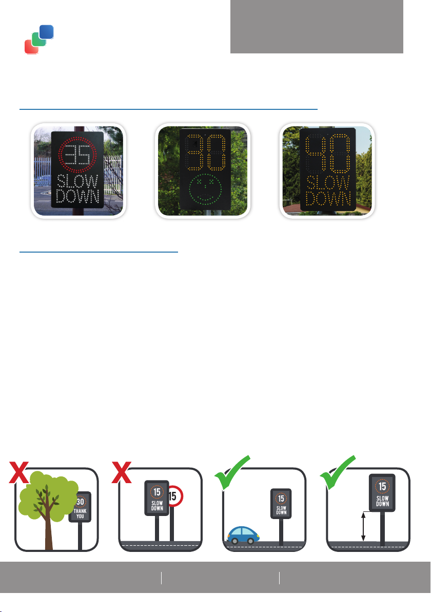
Below is a brief guidelines for the positions of your speed signs.
A minimum height of 2.15m must be allowed between the base of the sign and the ground.
The sign must be clearly visible to approaching traf c. Preferably on a clear straight road to allow
suf cient time to be seen by drivers.
The edge of the sign nearest the roadside should be not be less than 0.75m away.
Please ensure the unit does not obstruct any pre-existing road traf c signs.
Avoid placing our sign underneath overhanging trees/hedges, especially if using solar panels.This will
have a detrimental effect on the charging of the batteries plus tree sap will cause the sign to become
dirty and could cause the sign to be obscured.
The sign should not overhang an existing highway boundary without the adjoining owners’ consent.
Ensure the sign is mounted to a suitable post, or permission is granted to use an existing pole or lamp
post.
BEFORE INSTALLATION
2.15m

SID / SLR / SAM Speed Sign
Radar (Optional; pre-fi tted if applicable)
Sheet pole mounting bracket (Pre-fi tted)
Solar Charge Controller (Optional; pre-fi tted if applicable) (Fig 1.)
80w Solar Panel (Optional)
Solar Panel Mounting Bracket (Only solar powered models)
4 x U-bolts for solar panel mounting bracket for 76mm posts (Only solar powered models) (Fig 2.)
2 x 76mm clips to t the sheet pole mounting bracket to your post (Fig 3.)
USB Data Cable (Data radars only) (Fig 4.)
1 x Battery (excluding mains powered models) (Fig 5.)
2 x Batteries (Solar powered models only) (Fig 5.)
1 x Battery charging Cable (Battery powered model only) (Fig 6.)
1 x Battery Charger (Battery powered model only) (Fig 6.)
Keys (Fig 7.)
1.0 BOX CONTENTS
Batteries are not pre-installed, so will need to be tted into the unit once installed.
The batteries are pre-wired for correct polarity, do not alter this.
Each Yuassa 12v 22,000 AH battery weighs 7 kg each.
Each unit can hold up to 2 batteries, held in place by the battery clamps pictured below.
Fig 1. Fig 2. Fig 3. Fig 4. Fig 5. Fig 6. Fig 7.
1.1 BATTERIES
Battery Powered
1battery as standard
Main Powered
2 batteries and Solar
Charger Controller
Optional batteries for
intermittent power supply.
Solar Powered

Your unit has already been pre-programmed to the speed settings specied at the time of order.
If you wish to change the settings, follow the guide below.You are able to change;
1. The minium trigger speed
2. The maximum trigger speed
3. Length of time for LED illumination
2.0 PROGRAMMING YOUR SIGN
Dial S3 0 1 2 3 4 5 6789ABC D
Speed 0 5 10 15 20 25 30 35 40 45 50 55 60 65
2.1 Minimum Trigger Speed Setting : Dial S3
Dial S2 0 1 2 3 4 5 6789ABC D
Speed 30 35 40 45 50 55 60 65 70 75 80 85 90 95
2.2 Maximum Trigger Speed Settings : Dial S2
Dial S2 0 1 2 3 4 5 6789ABC D
Seconds 0 0.5 1 1.5 2 2.5 3 3.5 4 4.5 5 5.5 6 6.5
2.3 Length of time for Illumination Duration: Dial S1
Control Board inside your speed sign:
Using the above table, twist the S2 white dial to the value you require. Then, press and hold the
black button above to conrm and set the desired speed. (The new selected speed will display on
the front of the sign momentarily.)
Using the above table, twist the S3 white dial to the value you require. Then, press and hold the
black button above to conrm and set the desired speed. (The new selected speed will display on
the front of the sign momentarily.)
Using the above table, twist the S1 white dial to the value you require. Then, press and hold the
black button above to conrm and set the desired speed. (The new selected illumination duration
time will display on the front of the sign momentarily.)
S3 S2 S1

In your packaging, you will be supplied with an installation guide, but some
important information is outlined below.
Also supplied are 4 U-Shaped clamps, suitable for 76mm Diameter posts.
(Other sizes are available upon request.)
3.1 IMPORTANT INFORMATION
Always observe the correct polarity when making electrical connections. Reverse polarity
connection to a battery is a re hazard and may damage your solar regulator/charge
controller.
Do not walk or drop objects on the panel front or rear.
Do not use mirrors or any other objects to concentrate sunlight on the solar panels.
Always handle with care.
3.2 MOUNTING
Choose a location that is free from shade and as close as possible to South facing (in the
Northern hemisphere).
Always x to a solid and supportive surface capable of withstanding all expected loads
including the weight of the panel as well as those imposed by wind and snow.
For optimum performance tilt the panel at an angle of 70° facing south.
3.3 MAINTENENCE
Occasionally wipe the solar panel with a damp cloth (use only water and mild detergent) to
remove the build-up of dirt, salt, etc.
Batteries should be maintained in accordance with manufacturer’s instructions.
(printed on the side of the battery)
All wiring and connections should be regularly checked for integrity and corrosion.
3.4 TROUBLESHOOTING
If your solar panel does not seem to be performing properly start by addressing the following;
Inspect all electrical connections for any sign of corrosion or loose wiring.
Test the panel’s open circuit voltage (Voc). To reduce risk of sparking cover the panel before
disconnecting. Using a multi-meter set to DC Volts, measure the voltage across the +ve and
–ve terminals of the panel. In bright sunny conditions a reading of approx. 18to 22V should
be seen.
Verify the condition of the battery. Over time a battery will lose its ability to recharge,
especially after repeated heavy cycles of charge and deep discharge. Contact the battery’s
manufacturer for more detailed guidelines on battery testing.
Make sure your system is properly sized for your power requirements.
3.0 SOLAR PANEL INSTALLATION (optional extra)

VAS Speed Signs with Data Capture abilities, have 4GB of on-board storage.This
should be enough to store a lifetime’s worth of detection data.
Data is recorded continuously without the need for any settings to be altered.
SOFTWARE DOWNLOAD
To view recorded data, the ‘Kestrel Workbench’ software is required.
This is available on our website www.messagemaker.co.uk under ‘Downloads’.
VEHICLE ACTIVATED SPEED SIGNS
DATA CAPTURE SYSTEMS
Messagemaker
Displays
MANUAL
www.messagemaker.co.ukTel. 01737 774747sales@messagemaker.co.uk
USB LOCATION
SID and SAM Signs SLR Sign

IMPORTING DATA
Simply connect the radar via USB or
remote access (Bluetooth/Modem).
The Micro USB port is located on top of the radar
module as pictured below.
Here you can select the le location of
where the data is to be stored.
You are also able to select a date range in the
‘Filter’ section to dene what data is included
in the statistical analysis.
Click ‘OK’
Open the ‘Kestrel Workbench’ software
and Double click ‘Data Download’
2.
The download process will begin.
When the process is complete, the
window will report itself as idle.
3.
4.
1.
Need some help?
If you have a query regarding anything in this manual, or something else about your
sign(s) please do not hesitate to contact your account manager, or contact us using
the details below;
Call us: 01737 774747
Email: sales@messagemaker.co.uk

REPORT GENERATION
Kestrel Workbench has a built report generation feature, meaning that you can simply
select an amount of data for Workbench to perform a statistical analysis on.
The reports include vehicle count data and presents this across a series of charts. It is
important to note here that Continuous Wave (CW) Doppler radar technology does
not have the scope for accurate vehicle counting because it only collects speed and
direction information. Accurate counts require spatial information about passing vehicles
in order to determine vehicle lengths. As such, with the Kestrel K2 Pico Flex Radar, a
statistical average vehicle length value is used, which in practise amounts to 80-95%
accuracy.
CREATING A REPORT
Select ‘Report’.
This menu can also used to create K2 Projects
and LED Display Calibrations. Please contact our
team for more information.
Select ‘Basic Report’.
1. In Kestrel Workbench, go to File > New...
2.
3.
4.
5.
6.
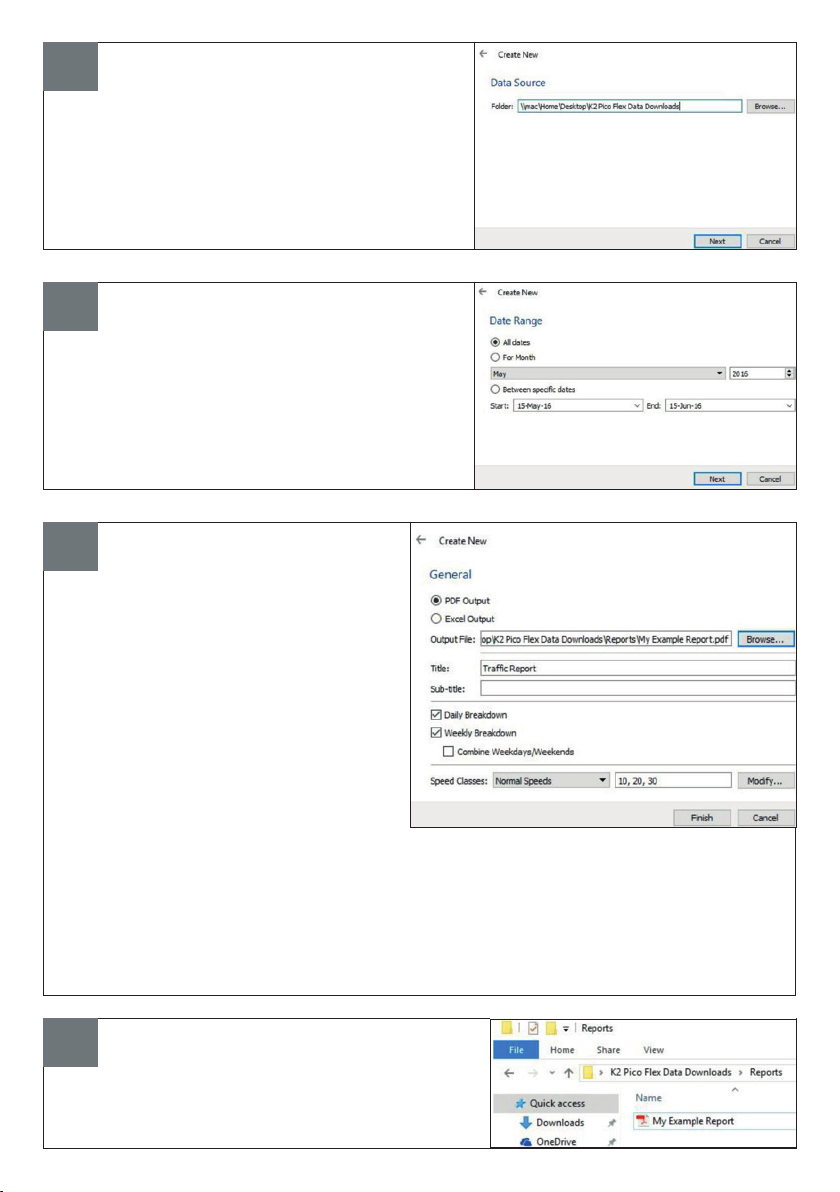
In the data source window, select the
location which the original data was
imported to.
Then press ‘Next’.
In the date range window, select which
data from all previous imports, will be
included in the report.
Then press ‘Next’
Select the type of output that you
want; either PDF or Excel.
You can change the location of the
output le, assign titles and select how
the data is to be displayed here.
The eld for ‘Speed Classes’ denes
which speed ranges are to be
included in the report. To dene the
speed range, enter the minimum and
maximum sppeds.
For example, entering 10, 20, 30 will create 3 data columns of vehicles travelling;
• under 10mph
• between 10mph and 20mph
• between 20mph and 30mph
7. With the desired settings, select ‘Finish’.
To open the report, go to the le via
your PC.
This manual suits for next models
2
Table of contents
Popular Lighting Equipment manuals by other brands


Nemalux
Nemalux AR Series installation manual

Larson Electronics
Larson Electronics EPL-WPLED-100W-RT-PSC instruction manual

GE
GE GERLB2465 Instruction guide

Quantum
Quantum ELM Replacement instructions

Avlite
Avlite AV60 Installation & service manual

Larson Electronics
Larson Electronics LEDLB-4-IR instruction manual


