Nemalux AR Series User manual

APPLICATION
AR luminaires are designed for use indoors, outdoors, wet locations, and areas containing moisture,
dirt, corrosion, vibration, and rough usage. NSF Models (ARxx-xxx-xx-xx-FS-XX) of the luminaire is
certied by NSF for use in Splash-zone and Non-Food areas of food processing locations as dened in
NSF-2. The AR luminaire is also certied for use on marine vessels inside, outside and in other severely
wet saltwater environments. Models ARXX-XXX-XX-XX-HZ-XX are certied for use in hazardous location
areas.
UL File Numbers: Nemalux General Location: E477827
Nemalux Hazardous Location: E477829
AR luminaires are suitable for use in the following areas as dened by the National Electrical Code
(NEC) and the Canadian Electrical Code (CEC):
Certications all models: UL 1598, UL 1598A and UL 8750;
CSA C22.2 No. 250.0 and CSA C22.2 No. 250.13
ABS Listed
Certications Hazardous Location models (ARXX-XXX-XX-XX-HZ-XX)
UL 844, CSA C22.2 No. 137
Hazardous Location Approved Locations:
Class I, Division 2, Groups ABCD, T4;
Class II, Division 2, Groups FG, T4A;
Class III;
Class I, Zone 2, Group IIC;
Zone 22
Certications NSF models (ARXX-XXX-XX-XX-FS-XX)
NSF/ANSI 2 Splash and Non-Food Zone
Housing: Copper-free Cast Aluminum with Polycarbonate lens
Input Voltage: Based on luminaire sux in table below: Sux - AC: 120-277 VAC | Sux - HV: 347-480
VAC
Inrush Current: AR (AC): Inrush Current Peak / >50% Duration 120V: 62A / 210uS 277V: 148A / 200uS
AR (HV): Inrush Current 347V: 118.4A / 97uS Peak / >50% Duration 480V: 148A / 79uS
Connections: 2 x 3/4”NPT Conduit | Black: Line | White: Neutral/Line 2 | Green: Ground
Optional: Violet (Purple): 0-10V Dimming (+) | Grey: 0-10V Dimming (-)
For connections use wire rated to a minimum of 90°C. Class 1 Wiring only.
Dimming control wires must be rated 300V minimum for luminaires with sux AC,
600V minimum for luminaires with sux HV.
Ingress Protection: IP66/67 | Suitable For Wet Locations. Marine Outside Type (Salt Water)
TM
Nemalux
I N DUSTRIAL
AR Series
rev. A-30
1-16
MADE IN CANADA
Installation Spec Sheet Webpage
The AR Series Installation Manual
*White xture only
WARNING
ATTENTION
Potential Electrostatic Charging Hazard
Risque potentiel de charge électrostatique
Avoid electrostatic discharge :
• Clean exterior lens surface with damp cloth only
• Éviter les décharges électrostatiques: nettoyer la surface extérieure
de la lentille uniquement avec un chion humide
TM
Nemalux
I N DUSTRIAL
AR Series
rev. A-30
2-16
MADE IN CANADA
Electrical Rating:
General Location (ARXX-XXX-XX-XX-GN-XX),
Food Safe (ARXX-XXX-XX-XX-FS-XX),
Hazardous Location (ARXX-XXX-XX-XX-HZ-XX)
APPLICATION CONT.
General Location High Intensity model
(ARXXH-XXX-XX-XX-GN-XX)
Temperature Range:
General Location (ARXX-XXX-XX-XX-GN-XX)
Food Safe (ARXX-XXX-XX-XX-FS-XX)
General Location High Intensity model
(ARXXH-XXX-XX-XX-GN-XX)
Hazardous Location (ARXX-XXX-XX-XX-HZ-XX)
LUMINANCE
AR10
AR15
AR20
AR25
AR30
RATED VOLTAGE
[Volts]
RATED WATTAGE
[Watts]
INPUT
VOLTAGE
AC
HV
AC
HV
AC
HV
AC
HV
AC
HV
120-277
347-480
120-277
347-480
120-277
347-480
120-277
347-480
120-277
347-480
107
129
145
145
190
187
247
248
312
310
FREQUENCY
[Hz]
50/60
50/60
50/60
50/60
50/60
50/60
50/60
50/60
50/60
50/60
LUMINANCE
AR20H
AR25H
AR30H
AR35H
AR40H
AR45H
AR50H
RATED VOLTAGE
[Volts]
RATED WATTAGE
[Watts]
INPUT
VOLTAGE
AC
HV
AC
HV
AC
HV
AC
HV
AC
HV
AC
HV
AC
HV
120-277
120-277
120-277
120-277
120-277
120-277
120-277
120-277
120-277
120-277
120-277
120-277
120-277
120-277
130
130
150
150
190
190
210
210
250
250
275
275
290
290
FREQUENCY
[Hz]
50/60
50/60
50/60
50/60
50/60
50/60
50/60
50/60
50/60
50/60
50/60
50/60
50/60
50/60
LUMINANCE
AR10, AR15,
AR20, AR25
AR30
AMBIENT TEMP
[°C]
INPUT
VOLTAGE
AC
HV
AC,HV Optical
AC Flood
HV Flood
-40 to 55
-40 to 50
-40 to 45
-40 to 40
-40 to 45
LUMINANCE
AR20H, AR25H
AR30H, AR40H
AR45H, AR50H
AMBIENT TEMP
[°C]
INPUT
VOLTAGE
AC
HV
AC
HV
AC
HV
-40 to 53
-40 to 48
-40 to 49
-40 to 40
-40 to 42
-40 to 40
LUMINANCE
AR10, AR15,
AR20
AR25
AR30
AMBIENT TEMP
[°C]
INPUT
VOLTAGE
AC
HV
AC
HV
AC
HV
-40 to 55
-40 to 54
-40 to 51
-40 to 44
-40 to 43
-40 to 43
AMBIENT TEMP
[°C]
CLASS I, DIV 2
T-CODES
T3C
T3C
T3C
T3B
T3
T3
-40 to 55
-40 to 51
-40 to 55
-40 to 50
-40 to 42
-40 to 40
CLASS II, DIV 2
T-CODES
CLASS I, DIV 2
T-CODES
T4A
T4
T4A
T4A
T4A
T3
T5
T5
T5
T5
T5
T5
ALL MODELS
OPTICAL MODELS FLOOD MODELS
To reduce the risk of electric shock,
disconnect the luminaire from the
supply circuit before opening for
installation and servicing. Keep
tightly closed when in operation.
WARNING / ATTENTION
To avoid the risk of re, explosion,
or electric shock, this product
should be installed, inspected,
and maintained by a qualied
electrician only, in accordance
with all applicable electrical
codes.
Éviter tout risque d'incendie,
d'explosion ou d'électrocution, ce
produit doit être installé, inspecté et
entretenu par un électricien qualié
uniquement, conformément à tous
codes électriques applicables.
WARNING / ATTENTION
Pour réduire le risque de choc
électrique, débranchez le luminaire
du circuit d'alimentation avant
l'ouverture pour l'installation et
entretien. Gardez hermétiquement
fermé pendant le fonctionnement.
CURRENT
[A]
1.0A/0.5A
1.0A/0.5A
1.3A/0.6A
1.3A/0.6A
1.5A/0.7A
1.5A/0.7A
1.7A/0.8A
1.7A/0.8A
2.0A/0.9A
2.0A/0.9A
2.3A/1.0A
2.3A/1.0A
2.4A/1.0A
2.4A/1.0A

3-16
MADE IN CANADA
TM
Nemalux
I N DUSTRIAL
AR Series
rev. A-30
5.0in
126mm
5.2in
132mm
21.1in
535mm
22.5in
570mm
0.5in
12.7mm
0.3in
6.8mm
0.5in
12.7mm
0.5in
12.7mm
0.5in
12.7mm
0.5in
12.7mm
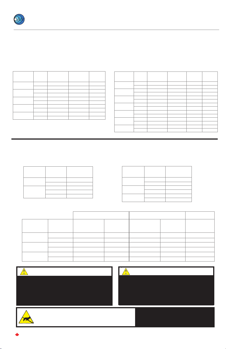
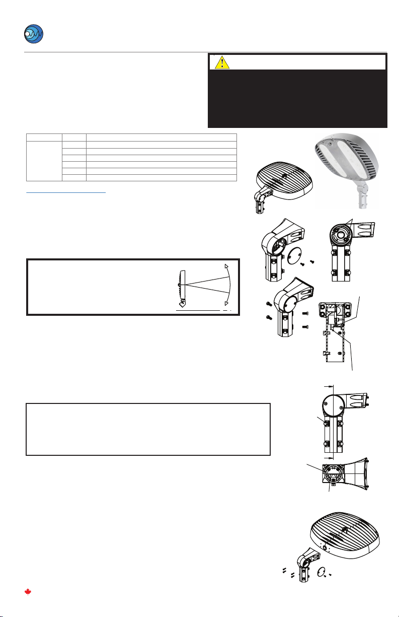
STEP 1.
Inspect shipping package and contents to ensure no damage
has occurred during shipping.
STEP 2.
Remove 8x M6 hex cap bracket mounting screws from head
and re-install with included Surface/Suspension Mount
Brackets. See diagram for orientation of brackets. Torque M6
bolts to 5 Nm (45 in-lbs).
STEP 3.
A) For surface mounting conguration, mount luminaire in
desired ceiling location using 4x 1/4-20 OR 4x M6 fasteners
and washers (Not provided). One mounting hole on each
bracket is keyed to allow partial pre-installation of two
fasteners for ease of install.
B) For ceiling mounting congurations, connect 4x anchors to
the 12.7mm (0.5”) holes. Suspension hardware (Not provided)
must be rated for a minimum of 180 lbs.
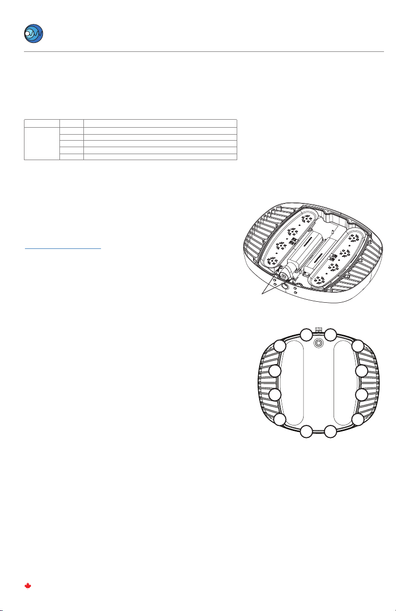
STEP 4.
Open AR Lens with a 7mm socket or wrench and
allow Lens to hang via retention strap.
Note:
Screws are captive fasteners and will remain attached to the
Lens for ease of reinstall and to prevent loss of fasteners.
STEP 5.
Make wiring connections from branch circuit conductors to
factory provided lead wires. Refer to NEC/CEC codes and
follow all applicable local standards. See wiring diagram on
Page 4.
AR-SM – SURFACE/CEILING MOUNT INSTALLATION
(Ordered Separately)
(All brackets are ordered separately)
Refer to alternate instructions if using, Hook, Wall, Pole or Yoke Mount
Step 5
Step 2
Step 3A
Step 3B
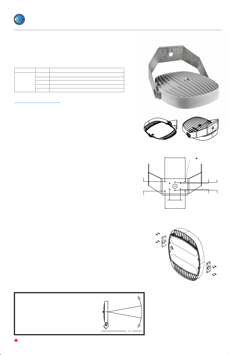
WARNING:
The AR Head must not face
upwards by any degree
beyond the vertical position
for Class II, Division 2,
Zone 22, and Class III
hazardous locations.
LIGHT BEAM
HORIZON
ATTENTION:
Le luminaire (AR) ne doit pas
être orientée vers le haut de
quelque degré que ce soit
au-delà de la position verticale
pour les emplacements
dangereux de Classe II,
Division 2, Zone 22 et Classe III

4-16
MADE IN CANADA
TM
Nemalux
I N DUSTRIAL
AR Series
rev. A-30
WIRING DIAGRAM
PS 1
PS 2
GROUND
(Factory)
BLACK LINE
WHITE NEUTRAL/LINE 2
GREEN GROUND
VIOLET PURPLE DIM +
GREY DIM
BLACK
WHITE
GREEN
VIOLET PURPLE
GREY
For 0-10V Analog Dimming Control, connect Violet (PURPLE) (+)
and Gray (-) to 0-10VDC control wiring:
• 0-10V Interface can be wired as Class 1 or Class 2
Circuit.
• LED Drivers will source a combined maximum of
400µA for control needs.
• 0-10V Controller must sink current from LED driver
0-10V control connections.
• Dimming controls must be certied and suitable
for the classication of the area of their installation
NOTE:
To aid in assembly and protection against ingress use of a
petrolatum or soap thickened mineral oil based thread
lubricant/sealant is necessary.
Un-used conduit opening must be plugged to maintain the
integrity of the enclosure.
STEP 6.
Close AR lens. Ensure the retention cable is not pinched between
AR Head and the AR Lens. Tighten lens bolts using a 7mm socket
or box wrench to 1.7 N-m (15 in-lbs) in the order designated in the
diagram to ensure gasket sealing. 5
6
7
8
9
10
11
12
1
23
4
Step 6

5-16
MADE IN CANADA
TM
Nemalux
I N DUSTRIAL
AR Series
rev. A-30
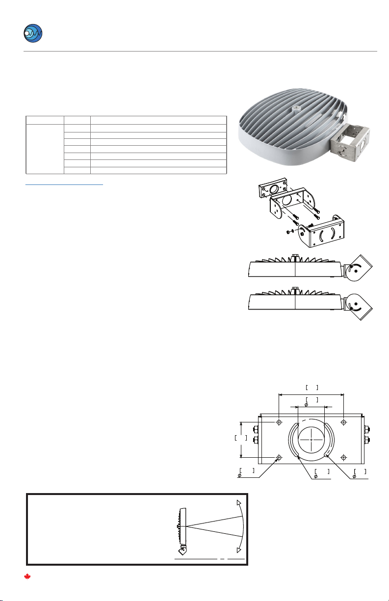
AR-PM – POLE MOUNT INSTALLATION1(Ordered Separately)
Refer to alternate instructions if using Conduit, Hook, Wall, Yoke Mount, or High Vibration Yoke
INSTALLATION STEPS
Step 3
Step 5
STEP 1.
Inspect shipping package and contents to ensure no
damage has occurred during shipping. Discard
surface/ceiling mounting bracket provided with AR
luminaire. Remove 4 x M6 bolts from supply side of luminaire
and disard.
STEP 2.
Install the provided plastic 3/4”bushing into side 3/4" NPT
entry.
STEP 3.
Install Pole Mount and gasket with adhesive side applied to
mount using included M6 bolts and washers.
Torque to 5 Nm (45 in-lbs)
STEP 4.
Thread luminaire assembly onto 1-1/2” NPT pole.
NOTE:
To aid in assembly and protection against ingress use of a
petrolatum or soap thickened mineral oil based thread
lubricant/sealant is necessary.
Un-used conduit opening must be plugged to maintain the
integrity of the enclosure.
STEP 5.
Insert and tension M6 set screw to pole to lock rotation.
STEP 6.
Resume installation instructions provided with luminaire.
(STEP 4 in AR Installation Instructions provided with
Luminaire)
SET SCREW
This AR-PM kit is intended for use with UL Listed AR luminaire as
marked on the luminaire nameplate.
Accessory Package Contents
AR-PM
PART NAMEQTY
1
1
4
4
1
1
POLE MOUNT
POLE MOUNT GASKET
M6 X 25mm HEX HEAD CAP SCREW
M6 FLAT WASHER
M6 X 16mm HEX HEAD CAP SCREW
3/4 NPT THREADED SMOOTH BORE BUSHING
1-1/2" NPT Entry
WARNING:
The AR Head must not face
upwards by any degree
beyond the vertical position
for Class II, Division 2,
Zone 22, and Class III
hazardous locations.
LIGHT BEAM
HORIZON
ATTENTION:
Le luminaire (AR) ne doit pas
être orientée vers le haut de
quelque degré que ce soit
au-delà de la position verticale
pour les emplacements
dangereux de Classe II,
Division 2, Zone 22 et Classe III

6-16
MADE IN CANADA
TM
Nemalux
I N DUSTRIAL
AR Series
rev. A-30
AR-WM – WALL MOUNT INSTALLATION (Ordered Separately)
Refer to alternate instructions if using Conduit, Hook, Pole, Yoke Mount, or High Vibration Yoke
STEP 1.
Inspect shipping package and contents to ensure no damage has occurred
during shipping. Discard surface/ceiling mounting bracket provided with AR
luminaire. Remove 4 x M6 bolts from supply side of luminaire and disard.
STEP 2.
Install provided 3/4 NPT conduit plugs in desired locations on wall mount.
To maintain ingress rating all NPT entries not used for wiring connections are
required to be plugged. Torque to 10 Nm (88 in-lbs)
NOTE:
To aid in assembly and protection against ingress use of a petrolatum or
soap thickened mineral oil based thread lubricant/sealant is necessary.
Un-used conduit opening must be plugged to maintain the integrity of the
enclosure.
STEP 3.
Install provided 3/4”NPT plastic bushing onto side NPT entry on AR head,
rotate so that ats are parallel to lens surface to avoid interference with
mount hardware.
STEP 4.
Install Wall Mount main body with included M6 bolts and washers and
adhesive backed gasket. Apply gasket to mount with adhesive backed side.
Torque to 5 Nm (45 in-lbs).
STEP 5.
Install Back Cover Plate with 4x M4 Flat head screws and adhesive backed
gasket. Apply gasket with adhesive side applied to mount main body.
Torque to 1.7 N-m (15 in-lbs).
STEP 6.
Mount luminaire assembly to desired location using
4x 1/4-20 OR M6 Screws or Bolts (Not Provided).
STEP 7.
Resume installation instructions provided with luminaire.
(STEP 4 in AR Installation Instructions provided with Luminaire)
Steps 2 through 5
[5.7in]
145mm
4 x
6.8mm THRU
ALL
[5.7in]
145mm
Step 6
This AR-WM kit is intended for use with UL Listed AR luminaire as
marked on the luminaire nameplate.
Accessory Package Contents
AR-WM
PART NAMEQTY
1
1
1
1
4
4
4
3
1
WALL MOUNT
WALL MOUNT PLATE
WALL MOUNT PLATE SIDE GASKET
WALL MOUNT GASKET
6 x 25mm SOCKET HEAD CAP SCREW
M4x 10mm FLAT HEAD SOCKET CAP SCREW
M6 FLAT WASHER
3/4 NPT HEX CAP PLUG
3/4 NPT THREADED SMOOTH BORE BUSHING
INSTALLATION STEPS
WARNING:
The AR Head must not face
upwards by any degree
beyond the vertical position
for Class II, Division 2,
Zone 22, and Class III
hazardous locations.
LIGHT BEAM
HORIZON
ATTENTION:
Le luminaire (AR) ne doit pas
être orientée vers le haut de
quelque degré que ce soit
au-delà de la position verticale
pour les emplacements
dangereux de Classe II,
Division 2, Zone 22 et Classe III
7-16
MADE IN CANADA
TM
Nemalux
I N DUSTRIAL
AR Series
rev. A-30
WARNING:
The AR Head must not face
upwards by any degree
beyond the vertical position
for Class II, Division 2,
Zone 22, and Class III
hazardous locations.
LIGHT BEAM
HORIZON
ATTENTION:
Le luminaire (AR) ne doit pas
être orientée vers le haut de
quelque degré que ce soit
au-delà de la position verticale
pour les emplacements
dangereux de Classe II,
Division 2, Zone 22 et Classe III
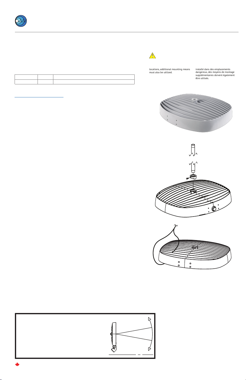
AR-YM – YOKE MOUNT INSTALLATION (Ordered Separately)
Refer to alternate instructions if using Conduit, Hook, Pole, Wall Mount, or High Vibration Yoke
STEP 1.
Inspect shipping package and contents to ensure no damage has occurred
during shipping. Discard surface/ceiling mounting bracket provided with
AR luminaire. Remove 4 x M6 bolts from supply side of luminaire and
disard.
STEP 2.
Install suitable wiring system to the conduit opening per CEC/NEC
requirements for the specic location of install.
NOTE:
To aid in assembly and protection against ingress use of a petrolatum or
soap thickened mineral oil based thread lubricant/sealant is necessary.
Un-used conduit opening must be plugged to maintain the integrity of the
enclosure.
STEP 3.
Loosely assemble Yoke mount with carriage bolts on inside and washers
and nuts on the outside.
NOTE:
Depending on which mounting hole is used in the curved slot, the
luminaire may be congured for an upward or downward adjustable swing.
STEP 4.
Thread installed wiring through openings in yoke mount cheek plate and
yoke mount bracket. Mount yoke assembly to luminaire using 4x M6 Socket
Head Cap Screws and Washers (Provided). Torque fasteners to 5 Nm (45
in-lbs).
STEP 5.
Mount luminaire assembly to desired location using 4x 1/4-20 OR M6
Screws or Bolts (Not Provided).
STEP 6.
Adjust and aim luminaire to desired position. Torque hardware
nuts to 9 N-m (80 in-lbs).
STEP 7.
Resume installation instructions provided with luminaire.
(STEP 4 in AR Installation Instructions provided with Luminaire)
Step 5
Step 3
This AR-YM kit is intended for use with UL Listed AR luminaire as
marked on the luminaire nameplate.
Accessory Package Contents
INSTALLATION STEPS
AR-YM
PART NAMEQTY
1
1
1
4
4
4
4
YOKE MOUNT A
YOKE MOUNT B
CHEEK PLATE
1/4-20 HEX NUT
1/4" FLAT WASHER
1/4-20 x 0.5in CARRIAGE BOLT
M6 x 25mm HEX HEAD CAP SCREW
4.3in
108.15mm
2.3in
59mm
0.27in
6.76mm
0.27in
6.8mm
1.7in
44mm
2.8in
70mm

8-16
MADE IN CANADA
TM
Nemalux
I N DUSTRIAL
AR Series
rev. A-30
AR-HK – HOOK PENDANT INSTALLATION (Ordered Separately)
Refer to alternate instructions if using Pendant, Wall, Pole, Yoke Mount, or High Vibration Yoke
Step 3
STEP 1.
Inspect shipping package and contents to ensure no damage has
occurred during shipping. Discard surface/ceiling mounting bracket
provided with AR luminaire.
STEP 2.
It is recommended to install Secondary Safety Cable by looping
appropriate steel cable or chain through the outer band of the unit and
fastening a closed loop. Secondary safety hardware must be rated for a
minimum of 180lbs. Secondary safety cables made from stainless steel
aircraft cable are available upon request.
STEP 3.
Slide anti-rotation lock onto suspension hook assembly and install hook
assembly into ¾ NPT threaded entry. Tighten to hand tight plus 1 to 2
turns. Slide anti-rotation lock into place and tighten set screw to lock unit
in place.
NOTE:
To aid in assembly and protection against ingress use of a petrolatum or
soap thickened mineral oil based thread lubricant/sealant is necessary.
Un-used conduit opening must be plugged to maintain the integrity of
the enclosure.
STEP 4.
Latch hook onto eye-bolt or other xed mounting loop. Mounting point
must be rated for a minimum of 180lbs.
STEP 5.
Install remaining loop of secondary safety chain or steel cable to suitable
mounting location and fasten securely.
STEP 6.
Resume installation instructions provided with luminaire. (STEP 4 in AR
Installation Instructions provided with Luminaire)
Step 2
This AR-HK kit is intended for use with UL Listed AR luminaire as
marked on the luminaire nameplate.
Accessory Package Contents
INSTALLATION STEPS
AR-HK
PART NAMEQTY
1
1PENDANT HOOK ASSEMBLY
ANTI-ROTATION ASSEMBLY
This kit contains NSF component Anti-Rotation-Lock
(1004-01-02-201)
9-16
MADE IN CANADA
TM
Nemalux
I N DUSTRIAL
AR Series
rev. A-30
INSTALLATION STEPS
AR is Not permitted for conduit only
mounting when installed in hazardous
locations, additional mounting means
must also be utilized.
AR n'est pas autorisé pour le montage
sur conduit uniquement lorsqu'il est
installé dans des emplacements
dangereux, des moyens de montage
supplémentaires doivent également
être utilisés.
WARNING / ATTENTION
AR-CM –
CONDUIT MOUNT INSTALLATION
(Ordered Separately)
Refer to alternate instructions if using Wall, Hook, Pole or Yoke Mount
Step 2
STEP 1.
Inspect shipping package and contents to ensure no damage has
occurred during shipping. Discard surface/ceiling mounting bracket
provided with AR luminaire.
STEP 2.
Slide anti-rotation lock onto suitably mounted hanging conduit or
luminaire hanger and install luminaire onto ¾”NPT threaded nipple.
Tighten to hand tight contact plus 1 to 2 turns. Slide anti-rotation lock
into place and tighten set screw to lock unit in place. Fixed Rigid Metal
Conduit must be suitably mounted to prevent rotation and system must
be rated for 180 lbs.
NOTE:
To aid in assembly and protection against ingress use of a petrolatum or
soap thickened mineral oil based thread lubricant/sealant is necessary.
Un-used conduit opening must be plugged to maintain the integrity of
the enclosure.
STEP 3.
Install Secondary Safety Cable by looping appropriate steel cable or chain
through the outer band of the unit and fastening a closed loop.
Secondary safety hardware must be rated for a minimum of 180lbs.
Install remaining loop of secondary safety chain or steel cable to suitable
mounting location and fasten securely. Secondary safety hardware must
be rated for 180lbs.
STEP 4.
Resume installation instructions provided with luminaire. (STEP 4 in AR
Installation Instructions provided with Luminaire)
Step 3
This AR-CM kit is intended for use with UL Listed AR luminaire as
marked on the luminaire nameplate.
Accessory Package Contents
AR-CM
PART NAMEQTY
1ANTI-ROTATION BRACKET ASSEMBLY
WARNING:
The AR Head must not face
upwards by any degree
beyond the vertical position
for Class II, Division 2,
Zone 22, and Class III
hazardous locations.
LIGHT BEAM
HORIZON
ATTENTION:
Le luminaire (AR) ne doit pas
être orientée vers le haut de
quelque degré que ce soit
au-delà de la position verticale
pour les emplacements
dangereux de Classe II,
Division 2, Zone 22 et Classe III
10-16
MADE IN CANADA
TM
Nemalux
I N DUSTRIAL
AR Series
rev. A-30
WARNING:
The AR Head must not face
upwards by any degree
beyond the vertical position
for Class II, Division 2,
Zone 22, and Class III
hazardous locations.
LIGHT BEAM
HORIZON
ATTENTION:
Le luminaire (AR) ne doit pas
être orientée vers le haut de
quelque degré que ce soit
au-delà de la position verticale
pour les emplacements
dangereux de Classe II,
Division 2, Zone 22 et Classe III
INSTALLATION STEPS
AR-YK – HIGH VIBRATION YOKE INSTALLATION (Ordered Separately)
Refer to alternate instructions if using Conduit, Hook, Pole, Wall Mount, or Yoke Mount
STEP 1.
Inspect shipping package and contents to ensure no damage has
occurred during shipping. Discard surface/ceiling mounting bracket
provided with AR luminaire. Remove 8 x M6 hex bolts from sides of
luminaire and discard.
STEP 2.
Mount AR high vibration yoke to mounting surface using a minimum of
4x ¼-20 or M6 fasteners (not provided).
STEP 3.
Install suitable wiring system to the conduit opening per CEC/NEC
requirements for the speci-c location of install.
NOTE:
To aid in assembly and protection against ingress use of a petrolatum or
soap thickened mineral oil based thread lubricant/sealant is necessary.
Un-used conduit opening must be plugged to maintain the integrity of
the enclosure.
STEP 4.
Mount AR Cheek Plates to sides of AR luminaire using 4x M6 at head cap
screws per side. Thread one cheek plate over installed wiring during
assembly. Torque fasteners to 5 Nm (45 in-lbs).
STEP 5.
Thread installed wiring through opening in AR high vibration yoke mount
and install AR luminaire into yoke. The raised circular bosses on the AR
cheek plates should register inside of the large circular holes on the AR
high vibration yoke mount arms. Rotate luminaire to aim in the desired
direction and fasten in place using 2x M6 socket head cap screws and at
washers per side. Torque fasteners to 5 Nm (45 in-lbs).
STEP 6.
Resume installation instructions provided with luminaire.
(STEP 4 in AR Installation Instructions provided with Luminaire)
Step 4
Step 2
This AR-YK kit is intended for use with UL Listed AR
luminaire as marked on the luminaire nameplate.
Accessory Package Contents
AR-YK
PART NAMEQTY
1
2
8
4
4
AR HIGH VIBRATION YOKE
CHEEK PLATE
M6 x 1 x 25mm SOCKET FLAT HEAD CAP SCREW
M6 FLAT WASHER
M6 x 1 x 16mm SOCKET HEAD CAP SCREW
8.0in
3.8in
203mm
95mm
2.3in 3.1in
59mm
4.3in
80mm
8.0in
108mm
203mm
0.3in
10 x
6.8mm
THRU ALL
11-16
MADE IN CANADA
TM
Nemalux
I N DUSTRIAL
AR Series
rev. A-30
AR-SP-AC – SURGE SUPPRESSOR KIT (Ordered Separately)
(Requires AR-SP-AC Surge Protector Accessory Kit)
• Protects against surges and transients per ANSI C62.41-2002 category
C high (10KV, 1.2/50S & 10KA, 8/20S) standard Combo waves and
(6KV, 100KHz) Ring wave
• Protects against surges and transients per new ANSI C82.77-5 2015
category C high (20KV, 1.2/50S & 10KA, 8/20S) standard Combo
waves and (6KV, 100KHz) Ring wave.
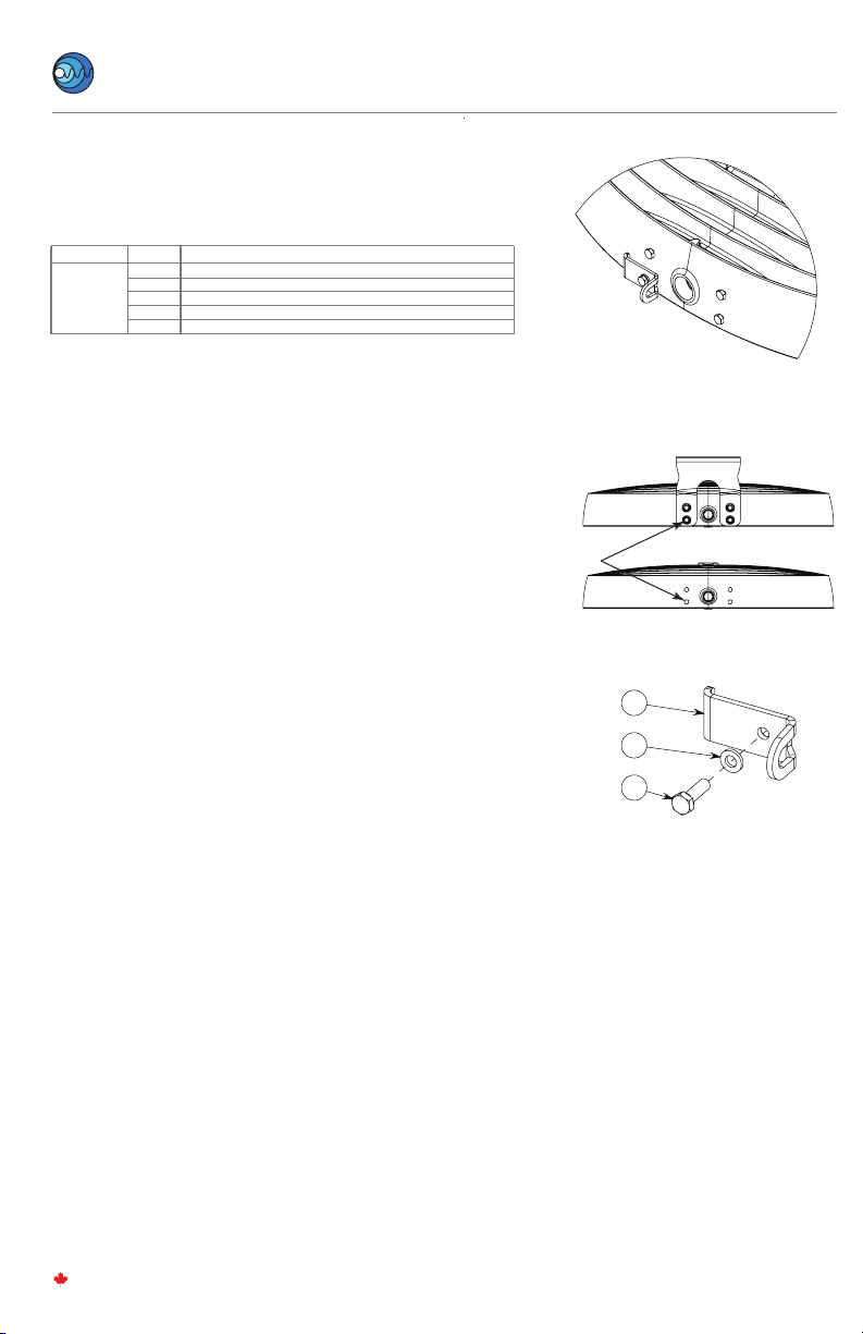
STEP 1.
Inspect shipping package and contents to ensure no damage has
occurred during shipping.
STEP 2.
Open AR Lens with 7mm hex socket driver. Allow Lens to hang via
retention strap.
NOTE:
Screws are captive fasteners and will remain attached to the Lens for
ease of reinstall and prevent loss of fasteners.
STEP 3.
Install provided double-sided tape along side of surge protector.
Remove backing paper and place between mounting points as shown,
with tape-side down. Install retention strap with two M3 fasteners and
ensure surge protector is held tightly in place.
STEP 4.
Wire according to wiring instructions on Page 2. Refer to NEC/CEC
codes and follow all applicable local standards.
STEP 5.
Close AR lens. Ensure the retention cable is not pinched between AR
Head and the AR Lens. Tighten lens bolts using a 7mm socket or box
wrench to 1.7 N-m (15 in-lbs) in the order designated in the diagram to
ensure gasket sealing.
5
6
7
8
9
10
11
12
1
23
4
Step 5
AR-SP-AC
PART NAMEQTY
1
1
1
2
2
FSP3-277-20KA SURGE PROTECTOR
3M VHB TAPE
SURGE SUPPRESSOR RETENTION STRAP
M3 x 8mm PAN HEAD PHILLIPS MACHINE SCREW
M3 FLAT WASHER
Step 3
M3 SCREW
This AR-SP-AC kit is intended for use with UL Listed AR luminaire as
marked on the luminaire nameplate.
Accessory Package Contents
INSTALLATION STEPS

12-16
MADE IN CANADA
TM
Nemalux
I N DUSTRIAL
AR Series
rev. A-30
1. Disconnect Line Input branch circuit conductor from splice or terminal connected to
Black leads from LED Driver. Re-connect Line Input branch circuit conductor to Black
wire from surge protector.
2. Connect Orange/Black wire from surge protector to splice or terminal connected to
Black leads from LED Drivers.
3. Connect White lead from surge protector to splice or terminal connected to Neutral
Input branch circuit conductor and White leads from LED Drivers.
4. Connect Green wire from surge protector to splice or terminal connected to
Grounding branch circuit conductor and green lead from luminaire case.
PS 1
PS 2
GROUND
(Factory)
BLACK
WHITE
ORANGE/BLACK
WHITE
GREEN
BLACK
VIOLET (PURPLE)
GREY
SURGE
SUPPRESSOR
WIRING DIAGRAM
(AR-SP-AC)
GREEN
WHITE
BLACK LINE
WHITE NEUTRAL/LINE 2
GREEN GROUND
VIOLET PURPLE DIM +
GREY DIM

• Protects against surges and transients per ANSI C62.41-2002 category
C high (10KV, 1.2/50S & 10KA, 8/20S) standard Combo waves and
(6KV, 100KHz) Ring wave
• Protects against surges and transients per new ANSI C82.77-5 2015
category C high (20KV, 1.2/50S & 10KA, 8/20S) standard Combo
waves and (6KV, 100KHz) Ring wave.
STEP 1.
Inspect shipping package and contents to ensure no damage has
occurred during shipping.
STEP 2.
Open AR Lens with 7mm hex socket driver. Allow Lens to hang via
retention strap.
NOTE:
Screws are captive fasteners and will remain attached to the Lens for ease of
reinstall and prevent loss of fasteners.
STEP 3.
Install provided double-sided tape along side of surge protector.
Remove backing paper and place between mounting points as shown,
with tape-side down. Install retention strap with two M3 fasteners and
ensure surge protector is held tightly in place.
STEP 4.
Wire according to wiring instructions on Page 2. Refer to NEC/CEC
codes and follow all applicable local standards.
STEP 5.
Close AR lens. Ensure the retention cable is not pinched between AR
Head and the AR Lens. Tighten lens bolts using a 7mm socket or box
wrench to 1.7 N-m (15 in-lbs) in the order designated in the diagram to
maintain ideal gasket sealing.
13-16
MADE IN CANADA
TM
Nemalux
I N DUSTRIAL
AR Series
rev. A-30
AR-SP-HV
PART NAME
QTY
1
1
1
2
2
FSP3-480-20KA SURGE PROTECTOR
3M VHB TAPE
SURGE SUPPRESSOR RETENTION STRAP
M3 x 8mm PAN HEAD PHILLIPS MACHINE SCREW
M3 FLAT WASHER
5
6
7
8
9
10
11
12
1
23
4
Step 5
Step 3
M3 SCREW
AR-SP-HV – SURGE SUPPRESSOR KIT (Ordered Separately)
(Requires AR-SP-HV Surge Protector Accessory Kit)
This AR-SP-HV kit is intended for use with UL Listed AR luminaire as
marked on the luminaire nameplate.
Accessory Package Contents
INSTALLATION STEPS

14-16
MADE IN CANADA
TM
Nemalux
I N DUSTRIAL
AR Series
rev. A-30
WIRING DIAGRAM
(AR-SP-HV)
1. Disconnect Line Input branch circuit conductor from splice or terminal connected
to Black leads from LED Driver. Re-connect Line Input branch circuit conductor to
Orange wire from surge protector.
2. Connect Orange/Black wire from surge protector to splice or terminal connected to
Black leads from LED Drivers.
3. Disconnect Neutral Input branch circuit conductor from splice or terminal
connected to White leads from LED Driver. Re-connect Neutral Input branch circuit
conductorto Yellow wire from surge protector.
4. Connect Yellow/Black wire from surge protector to splice or terminal connected to
White leads from LED Drivers.
5. Connect Green wire from surge protector to splice or terminal connected to
Grounding branch circuit conductor and green lead from luminaire case.
PS 1
PS 2
GROUND
(Factory)
BLACK
WHITE
ORANGE/BLACK
WHITE
GREEN
BLACK
VIOLET (PURPLE)
GREY
SURGE
SUPPRESSOR
GREEN
WHITE
BLACK - LINE
WHITE - NEUTRAL/LINE 2
GREEN - GROUND
VIOLET (PURPLE) - DIM (+)
GREY - DIM (-)
STEP 1. Inspect shipping package and contents to ensure no damage has
occurred during shipping.
STEP 2. Remove both M6 at head cap screws using a 4mm hex key and remove
sealed cap. If required angle is known, adjust luminaire angle by loosening two M8
socket head cap screws inside the slip tter pole mount using a 6mm hex key.
After aiming torque M8 socket head cap screws to 17N-m (13ft-lb).
NOTE: Aiming angle can be adjusted after Step 6.
STEP 3.
Install slip tter pole mount onto pole. Poles equivalent in size to 1-1/2" or 2" trade
size pipe or conduit are to be used. Ensure slip tter pole mount is fully seated on
top of pole at the internal stops.
Aim and secure slip tter pole mount using the six provided 3/8” hex bolts. Torque to
27N-m (20ft-lb)
NOTE: Aiming can be adjusted up to 180° in either direction after installation by loosening
the 6 hex bolts and tightening again to 27 N-m (20 ft-lb). DO NOT TURN BEYOND 180° as
this will induce twist and strain on conductors after wiring.
STEP 4.
Install a suitable wiring system that complies with the wiring methods permitted
in the Canadian Electrical Code or the National Electrical Code for the classication
of the hazardous locations area of installation.
STEP 5. Ensure wiring system has appropriate strain relief in the luminaire by tying a
large enough knot using the supply eld wiring in the wiring compartment such that
it cannot be pulled through the 3/4" inch NPT entry of the luminaire.
STEP 6. Secure slip tter pole mount to luminaire with four M6 hex head cap screws
provided using a 10mm socket. Torque to 7N-m (62in-lbs)
Step 7. Close sealed cap on slip tter pole mount. Torque to 7N-m (62in-lbs)
Step 8. Follow the wiring instructions specied in the main installation instructions
provided with the AR luminaire as applicable for making connections with the luminaire
lead wires and testing the system.
15-16
MADE IN CANADA
TM
Nemalux
I N DUSTRIAL
AR Series
rev. A-30
WARNING / ATTENTION
INSTALLATION STEPS
AR-SFY – SLIP FITTER YOKE MOUNT
(Ordered Separately)
This AR-SFY kit is intended for use with UL Listed
AR luminaire as marked on the luminaire nameplate.
Accessory Package Contents
AR-SFY
PART NAMEQTY
2
1
2
6
4
1
M6 X 16mm FLAT HEX HEAD SOCKET CAP SCREW
SEALED CAP
M8 X 25mm SOCKET HEAD CAP SCREWS
3/8” HEX BOLTS
M6 X 16mm HEX HEAD CAP SCREW
SLIP FITTER YOKE MOUNT (2x PIECES)
M8 ADJUSTMENT SCREWS
Listing for Class II, Division 2, Zone
22, Class III, Nonrecessed Marine
Luminaire and the IP66 or IP66/67
rating are Limited to using the
mount for mechanical support only
and not part of the wiring system.
BORE SIZED FOR 2"
TRADE SIZE POLE
53-63mm (2 1-8" TO
2 7-16") DIAMETER
6 X SET SCREW
B
B
INNER STEP BORE SIZED FOR 1.5" TRADE SIZE POLE
46mm - 50mm (1 13-16" TO 2")
SECTION B-B
BOTTOM OUT STEP FOR
TRADE SIZE 1.5" POLE
BOTTOM OUT STEP FOR
TRADE SIZE 2" POLE
Warning: Listing for Class II, Division 2,
Zone 22, Class III, Nonrecessed Marine
Luminaire and the IP66 or IP66/67 rating
are Limited to using the mount for
mechanical support only (¾” NPT Conduit
entry covered by mount is to be plugged
using provided plugs) and not part of the
wiring system.
Luminaires marins de classe II, division 2, zone 22,
classe III, non-encastré et la classification IP66 ou
IP66/67 sont limitées à l'utilisation du support
pour un support mécanique uniquement (l'entrée
de conduit ¾” NPT couverte par le support doit
être branchée à l'aide des bouchons fournies).
Il n'est pas autorisé à être utilisé pour le système
de câblage.
Luminaires marins de classe II, division 2,
zone 22, classe III, non-encastré et la
classication IP66 ou IP66 / 67 sont
limitées à l'utilisation du support pour un
support mécanique uniquement (l'entrée
de conduit ¾”NPT couverte par le
support doit être branchée à l'aide des
bouchons fournies). Il n'est pas autorisé à
être utilisé pour le système de câblage.
WARNING:
The AR Head must not face
upwards by any degree
beyond the vertical position
for Class II, Division 2,
Zone 22, and Class III
hazardous locations.
LIGHT BEAM
HORIZON
ATTENTION:
Le luminaire (AR) ne doit pas
être orientée vers le haut de
quelque degré que ce soit
au-delà de la position verticale
pour les emplacements
dangereux de Classe II,
Division 2, Zone 22 et Classe III
STEP 1.
Remove the bottom-left pre-installed M6 x 16mm Hex Cap Screw.
STEP 2.
Install bracket on AR luminaire as shown using supplied M6 x 20mm Hex
Cap Screw. Torque M6 x 20mm Hex Cap Screw to 40 in-lbs (4.5 Nm). It is
strongly recommended that a medium or high strength thread-locker be
used when installing the bracket. For units using surface or suspension
mounting, install safety kit hardware on top of the surface mount or
suspension mount brackets in the same location as shown.
STEP 3.
Attach stainless steel chain to safety kit bracket using stainless steel oval
shaped threaded connecting link.
STEP 4.
Attach loose end of chain. Secondary safety mounting point must be
suitable for supporting a minimum of 120lbs:
- Attach loose end of stainless steel chain to xed eye-bolt (not
supplied) using the second stainless steel oval shaped threaded
connecting link.
- Alternate attachment method: Wrap loose end of chain around
xed beam or other immovable support and create a closed loop
using the second stainless steel oval shaped threaded
connecting link. Supporting beam or structure must form a
closed loop to prevent the secondary safety chain from slipping
o or becoming unhooked.
16-16
MADE IN CANADA
TM
Nemalux
I N DUSTRIAL
AR Series
rev. A-30
Step 2
Step 1
AR-SK-##
PART NAMEQTY
1
1
1
2
1
1003-01-02-301 (ZLM Secondary Safety)
M6 Flat Washer
M6 x 20mm Hex Cap Screw
Oval Shaped Threaded Connecting Link
Stainless Steel Chain, 1/8”Trade Size
AR-SK-## – SECONDARY SAFETY KIT (Ordered Separately)
This AR-K-## kit is intended for use with UL Listed AR luminaire as
marked on the luminaire nameplate.
Accessory Package Contents
1
2
3
M6 SCREW
This manual suits for next models
12
Other Nemalux Lighting Equipment manuals


Popular Lighting Equipment manuals by other brands

Spotlight
Spotlight HAL LED 55 XL user manual

MJ LED LIGHTNING
MJ LED LIGHTNING MJ-2610D18-4IN1 user manual

Williams
Williams 96 Series installation instructions

Etlin-Daniels
Etlin-Daniels RTP42 Series Installation

iGuzzini
iGuzzini UNDERSCORE 15 manual

Frankfurt Laser Company
Frankfurt Laser Company FLTT Series manual


Lumineux
Lumineux Leighton 14W manual

Nicols
Nicols MINI CURVE RGBW user guide

Remington Solar
Remington Solar SUN SHOCK manual

Vision & Control
Vision & Control R-CLR-100x73-G523-SL Installation and operating instructions

EuroLite
EuroLite Audience Blinder user manual

Chauvet
Chauvet DMX MEGA STROBE III user manual