Luminar Outdoor 70278 Assembly instructions

Visit our website at: http://www.harborfreight.com
Owner’s Manual & Safety Instructions
Save This Manual Keep this manual for the safety warnings and precautions, assembly,
operating, inspection, maintenance and cleaning procedures. Write the product’s serial number in the
back of the manual near the assembly diagram (or month and year of purchase if product has no number).
Keep this manual and the receipt in a safe and dry place for future reference. 22i
When unpacking, make sure that the product is intact
and undamaged. If any parts are missing or broken,
please call 1-888-866-5797 as soon as possible.
Copyright©2022 by Harbor Freight Tools®. All rights reserved.
No portion of this manual or any artwork contained herein may be reproduced in
any shape or form without the express written consent of Harbor Freight Tools.
Diagrams within this manual may not be drawn proportionally. Due to continuing
improvements, actual product may differ slightly from the product described herein.
Tools required for assembly and service may not be included.
Read this material before using this product.
Failure to do so can result in serious injury.
SAVE THIS MANUAL.

Page 2 For technical questions, please call 1-888-866-5797. Item 70278
WARNING SYMBOLS AND DEFINITIONS
This is the safety alert symbol. It is used to alert you to potential personal injury hazards.
Obey all safety messages that follow this symbol to avoid possible injury or death.
Indicates a hazardous situation which, if not avoided,
will result in death or serious injury.
Indicates a hazardous situation which, if not avoided,
could result in death or serious injury.
Indicates a hazardous situation which, if not avoided,
could result in minor or moderate injury.
Addresses practices not related to personal injury.
IMPORTANT SAFETY INSTRUCTIONS
1. Do not mount or place near gas or electric heaters,
fireplaces, candles or other similar sources of heat.
2. Do not use this product for other
than its intended use.
3. Do not close doors or windows on the
product or extension cords as this may
damage the wire insulation.
4. Do not cover the product with cloth, paper or any
material not part of the product when in use.
5. Read and follow all instructions that are on
the product or provided with the product.
6. Keep proper footing and balance at
all times during installation.
7. The warnings, precautions, and instructions
discussed in this instruction manual cannot
cover all possible conditions and situations
that may occur. It must be understood by the
operator that common sense and caution are
factors which cannot be built into this product,
but must be supplied by the operator.
SAVE THESE INSTRUCTIONS.
SPECIFICATIONS
Cable Length 66 ft
Capacity Supports up to six sets of 25 foot string lights

Page 3For technical questions, please call 1-888-866-5797.Item 70278
Installation
1. Disassemble a Rope Clamp, and then lay one end
of the Cable in the Clamp around the threaded
posts to form a loop as illustrated in Figure A:.
2. Place the Lock over the threaded posts of
the Clamp, resting on top of the Cable.
Note: Make sure the Cable end extends slightly
past the Rope Clamp and is visible when
the Lock is resting on top of the Cable.
3. Thread the Nuts onto the threaded
posts until snug against the Lock.
Cable
Nuts
Clamp
Lock
Figure A:
4. Tighten the Nuts with the included Wrench to secure
the Cable within the Rope Clamp. See Figure B:.
Cable
Wrench
Rope Clamp
Nuts
Figure B:
5. Determine the desired location of the Cable, and
mark the locations for mounting the Wall Mounts.
6. Place a Wall mount into the Cable Loop,
and secure the Wall Mount in one of the
desired mounting locations with two Wood
Screws as illustrated in Figure C:.
Wall Mount
Cable Loop
Wood Screw
Figure C:
7. Mount the remaining Wall Mount(s) in the desired
mounting locations with Wood Screws as before.
Note: Most mounting scenarios will use two of the four
Wall Mounts for stringing the Cable between two points,
but additional Wall mounts can be used to allow for the
Cable to bend around corners, extra support, etc.
8. If using more than two Wall Mounts, route the Cable
through all of them except for the last Wall Mount.

Page 4 For technical questions, please call 1-888-866-5797. Item 70278
9. Hook the Turnbuckle onto the last Wall
mount as illustrated in Figure D:.
10. Thread the remaining end of the Cable through
the eyelet of the Turnbuckle as illustrated in
Figure D:. Pull excess Cable through the
eyelet until the Cable is taut, then relax the
tension slightly to allow a little slack.
11. Disassemble the remaining Rope Clamp, and then
lay the Cable in the Clamp around the threaded
posts to form a loop as illustrated in Figure A:
on page 3, with the excess cable outside of
the Rope Clamp as illustrated in Figure D:.
12. Place the Lock over the threaded posts of
the Clamp, resting on top of the Cable as
illustrated in Figure A: on page 3.
13. Thread the Nuts onto the threaded posts
until snug against the Lock as illustrated
in Figure A: on page 3.
14. Tighten the Nuts with the included Wrench
to secure the Cable within the Rope Clamp
as illustrated in Figure B: on page 3.
Wall Mount
Cable Loop
Turnbuckle
Rope Clamp
Screw
Screw
Excess Cable
Figure D:
15. Turn / tighten the Turnbuckle to remove the
slack in the Cable as illustrated in Figure E:.
Note: If tightening the Turnbuckle through its
adjustment range does not remove all of the
slack from the Cable, repeat steps 10 through
14 leaving less slack in the Cable.
CAUTION! Do not overtighten the
Turnbuckle! Cable failure can result.
Turnbuckle
Cable
Figure E:
16. If desired, loosely wrap the Light String
around the Cable so it may support the
Light String in multiple locations.
17. The Light String may be secured to
the Cable in one of three ways:
a. Option 1: Hang the individual lights from the
Cable using S-Hooks (not included) hooked
through the eyelet on the back of the Light.
b. Option 2: Hang the individual lights from
the Cable using Zip Ties looped through
the eyelet on the back of the Light. Snip
the Zip tie close to its square lock.
c. Option 3: Hang the individual lights from the
Cable using Zip Ties looped around the Cable
and Light String on either side of the Light.
Snip the Zip tie close to its square lock.
Light
S-Hook
Zip Tie
Eyelet
1 2 3
Figure F:

Page 5For technical questions, please call 1-888-866-5797.Item 70278
Maintenance
1. PERIODICALLY, inspect the general
condition of the hardware. Check for:
• loose hardware,
• misalignment or binding of parts,
• cracked or broken parts, and
• any other condition that may
affect its safe operation.
Record Product’s Serial Number Here:
Note: If product has no serial number, record month and year of purchase instead.
Note: Replacement parts are not available for this item. Reference UPC 193175494559.
Page 6 For technical questions, please call 1-888-866-5797. Item 70278
Parts List and Diagram
PLEASE READ THE FOLLOWING CAREFULLY
THE MANUFACTURER AND/OR DISTRIBUTOR HAS PROVIDED THE PARTS LIST AND ASSEMBLY DIAGRAM
IN THIS MANUAL AS A REFERENCE TOOL ONLY. NEITHER THE MANUFACTURER OR DISTRIBUTOR
MAKES ANY REPRESENTATION OR WARRANTY OF ANY KIND TO THE BUYER THAT HE OR SHE IS
QUALIFIED TO MAKE ANY REPAIRS TO THE PRODUCT, OR THAT HE OR SHE IS QUALIFIED TO REPLACE
ANY PARTS OF THE PRODUCT. IN FACT, THE MANUFACTURER AND/OR DISTRIBUTOR EXPRESSLY
STATES THAT ALL REPAIRS AND PARTS REPLACEMENTS SHOULD BE UNDERTAKEN BY CERTIFIED AND
LICENSED TECHNICIANS, AND NOT BY THE BUYER. THE BUYER ASSUMES ALL RISK AND LIABILITY
ARISING OUT OF HIS OR HER REPAIRS TO THE ORIGINAL PRODUCT OR REPLACEMENT PARTS
THERETO, OR ARISING OUT OF HIS OR HER INSTALLATION OF REPLACEMENT PARTS THERETO.
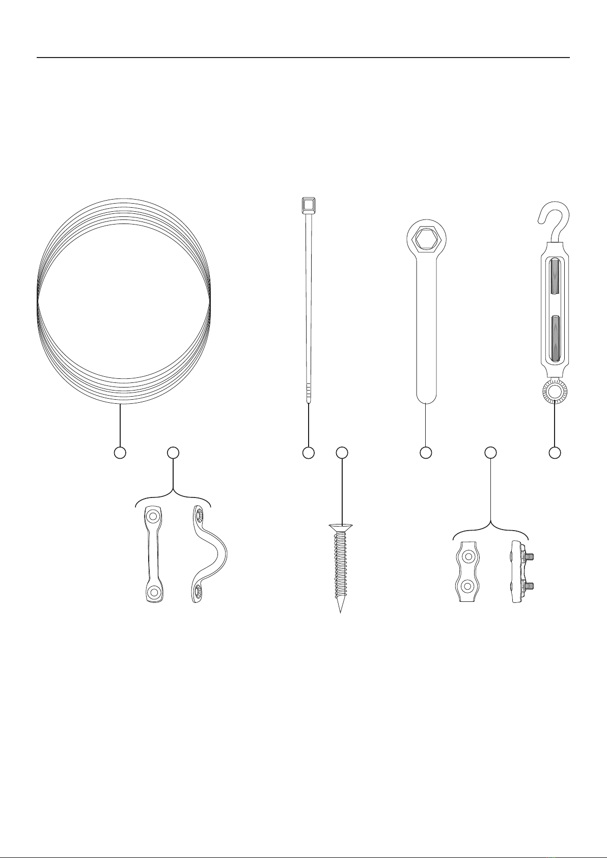
Parts List
Part Description Qty
1 Cable 1
2Zip Tie 120
3 Wrench 1
4 Turnbuckle 1
Part Description Qty
5 Wood Screw 8
6 Wall Mount 4
7 Rope Clamp 2
Page 7For technical questions, please call 1-888-866-5797.Item 70278
Parts Diagram
1234
5
67

26677 Agoura Road • Calabasas, CA 91302 • 1-888-866-5797
Limited 90 Day Warranty
Harbor Freight Tools Co. makes every effort to assure that its products meet high quality and durability standards,
and warrants to the original purchaser that this product is free from defects in materials and workmanship
for the period of 90 days from the date of purchase. This warranty does not apply to damage due directly
or indirectly, to misuse, abuse, negligence or accidents, repairs or alterations outside our facilities, criminal
activity, improper installation, normal wear and tear, or to lack of maintenance. We shall in no event be liable
for death, injuries to persons or property, or for incidental, contingent, special or consequential damages
arising from the use of our product. Some states do not allow the exclusion or limitation of incidental or
consequential damages, so the above limitation of exclusion may not apply to you. This warranty is expressly
in lieu of all other warranties, express or implied, including the warranties of merchantability and fitness.
To take advantage of this warranty, the product or part must be returned to us with transportation charges
prepaid. Proof of purchase date and an explanation of the complaint must accompany the merchandise.
If our inspection verifies the defect, we will either repair or replace the product at our election or we may
elect to refund the purchase price if we cannot readily and quickly provide you with a replacement. We will
return repaired products at our expense, but if we determine there is no defect, or that the defect resulted
from causes not within the scope of our warranty, then you must bear the cost of returning the product.
This warranty gives you specific legal rights and you may also have other rights which vary from state to state.
Table of contents
Other Luminar Outdoor Lighting Equipment manuals


