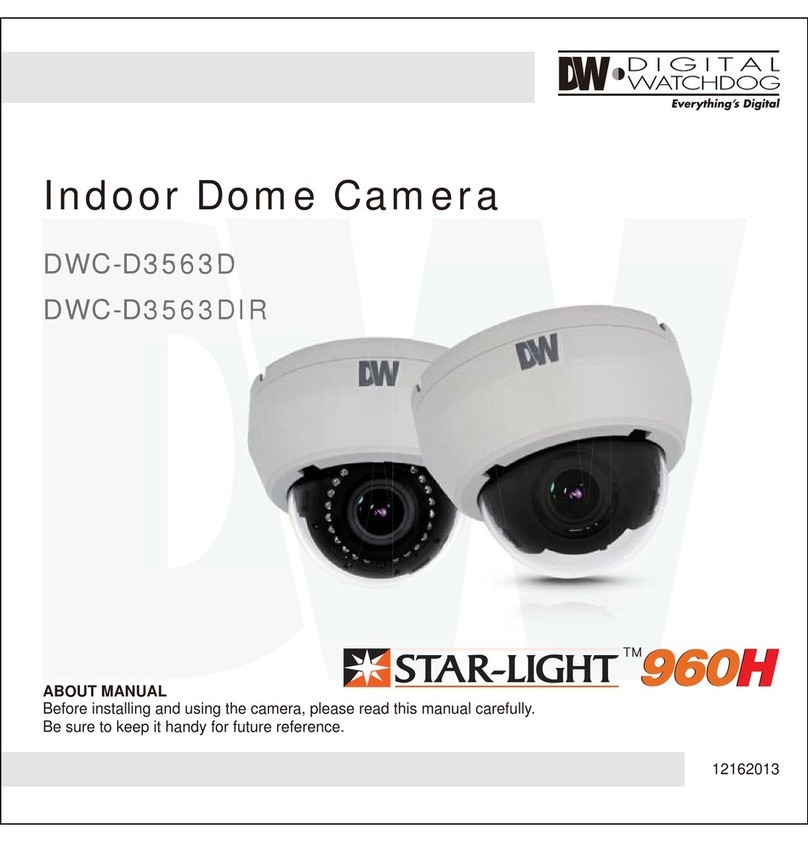
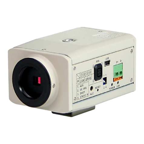
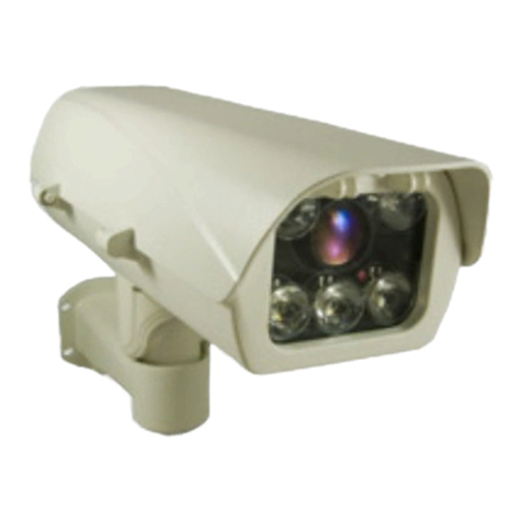
messaoa NDR721 User manual

Indoor IR Dome Network Camera
Quick Start
Guide
201409 721 A1
NDR721

1
English
1 Product Overview
1.1 Physical Description & Connection
Connections
Product Side ViewProduct Front View
DC Power
LAN
Lens
IR LED
Slide lock
Cable side cover
A
B
B
A
1. Identify the type of network device.
2. If the network device supports PoE (Power over Ethernet) function, simply connect the camera to it via Ethernet cable.
3. If not, both Ethernet cable and DC adaptor should connect to device

2
English
2 Installation
2.1 Package Content
2.2 Installation
2.2.1 Mounting the Camera
The Camera Ceiling Mount Installation Pack
Quick Installation Guide
Screws & Anchors Alignment Sticker
Lens adjustment tool
AB
C D
1. Place the alignment sticker on the ceiling which was preferred and drill three holes into the ceiling for cable and screws
2. Connect and route Ethernet cable or DC cable through the ceiling
(Note: remove the cable side cover once the cable route from the side)
3. Attach the camera to the ceiling by two screws.
(Note: The torque of electric screwdriver is recommended less than 6kgf-cm.)
4. Place the cover into the camera and ensured it locked.
Lens direction indicator
321 4
Indoor IR Dome Network Camera
Quick Start
Guide
201409 721 A1
NDR721

3
English
2.2.2 Tuning the Camera
1. Push the slide lock rightward to remove the dome cover
2. Adjust tilt angle by turning tilt adjustment screws
3. Fit the lens adjustment tool to lens and tune up focus by adjustment tool
4. Place the dome cover into camera module and ensured it locked
Rotate
Tilt adjustment screw
Focus
3
2
14
3 Connection
3.1 Assigning IP Address
2. Check the checkbox to select a camera device from the list.
3. The IP Camera may be assigned with a valid IP address via DHCP server. It can be also manually given a static IP address.
To do so, click on “Set IP”, and then input the IP, Subnet Mask and Gateway. Input account info if the camera is password
protected. (Default ID/Password : admin/1234)
4. Click on the “Browse” button to get access to the camera web page immediately.
1. Launch Discovery Tool (IPCAMDiscovery.exe). The tool will start searching and then displaying the cameras on the
Device List after they are found.
30
admin

4
English
3.2 Accessing the Camera
2. The live video of the camera can be played with a RTSP player, such as VLC or QuickTime. The network URL is rtsp://
Camera IP/stream1. The example given below is that live video is displayed with QuickTime player.
1. Launch IE browser and input the IP address of the camera, or click on “Browse” button on Discovery Tool.The web page
with video will then be shown as below.
3.3 Wireless Setting
3.3.1 Manual Setup
Note USB WiFi Dongle as optional parts for WiFi function
4. Once the setting complete, disconnect the Ethernet cable and then reboot the camera.
3. Type in the SSID and shared key same as what set on your router/AP and click the save button.
1. If the network device supports PoE function, simply connect the camera to it via Ethernet cable.
Otherwise both Ethernet cable and DC cable should connect to device.
2. Enter the web page setup > Network > Wireless
Choose the AP which want to be connected and click the “Select”

5
English
3.3.2 WiFi Direct Mode for mobile device
2. Scan the camera AP from smart phone/tablet WiFi Setup menu and link to the camera WiFi AP.
1. Press WiFi Mode button on camera over 1 sec but less than 3 sec, Amber LED turns on. The camera will act as a WiFi AP at
meantime.
3. Access the camera web page http://192.168.1.1/mobile by browser or scan the QR code as below Enter to “WiFi setting”
to type in the SSID and shared key same as what set on your WiFi router/AP and click the save button
4. The camera WiFi will switch back to client mode and link with the congured WiFi router/AP automatically.

6
English
3.3.3 WPS Function
WPS
1. Press the WPS (WiFi Protected Setup) button on your WiFi router/AP to trigger connection function
2. Press WiFi mode button on camera over 3 seconds then LED1 and LED2 starts to ash (the Amber LED and Green LED
start to ashing every 1 second which only last 2 minutes)
3. Once successful connection or WPS function timeout (2 minutes), the LED2 (Green) keeps steady on

7
简体中文
1 产品概述
1.1 产品特征 & 接线
接线
侧视图前视图
DC 电源
LAN
镜头
红外灯
滑锁
穿线孔侧盖
A
B
B
A
1. 确定选用的网络设备的类型;
2. 如果网络设备支持 PoE ( 以太网供电 ) 功能,只需使用一根网线连接摄像机和该网络设备;
3. 如不支持 PoE,请使用 DC 电源线连接网路设备。

8
简体中文
2 安装摄像机
2.1 标准配备
2.2 安装步骤
2.2.1 摄像机机身安装
摄像机 天花板安装配件
快速安装指南
螺丝 & 壁虎 安装模板贴纸
镜头调节工具
AB
C D
1. 安装模板贴纸粘贴到安装位置,根据贴纸上的安装孔位置钻孔;
2. 网线或 DC 电源适配器接线穿过天花板上接线孔;
( 注意:取下摄像机机身上的穿线孔侧盖便于接线 )
3. 用两个螺丝将摄像机固定到天花板上;
( 注意:建议使用扭矩小于 6kgf-cm 的电动起子 )
4. 安装并固定摄像机外壳。
镜头方向指示
321 4
室内红外网络半球摄像机
快速安装指南
201409 721 A1
NDR721

9
简体中文
2.2.2 调节摄像机
1. 如图所示,向右滑动滑锁,取下半球外壳;
2. 旋转倾斜调节螺丝,调节镜头倾斜角度;
3. 将镜头调节工具固定到摄像机镜头上,调节镜头对焦;
4. 将半球外壳安装回摄像机机身,并拧紧固定。
旋转
倾斜调节螺丝
对焦
3
2
14
3 连接摄像机
3.1 分配 IP 地址
2. 从列表中选择摄像机,勾选对应的复选框。
3. DHCP 服务器可以自动为网络摄像机分配一个有效的 IP 地址,用户也可以手动设置一个静态 IP 地址。
手动设置 IP 地址时,点击“Set IP”, 然后输入 IP 地址、子网掩码和网关。如果摄像机设置了密码保护,请输入对
应的帐号。( 默认帐号和密码为:admin/1234)
4. 点击“Browse”按钮, 登录摄像机网页界面。
1. 打开 Discovery Tool (IPCAMDiscovery.exe),自动搜索并在 Device List 中显示搜索到的摄像机。
admin
30

10
简体中文
3.2 访问摄像机
2. 用户可使用 RTSP 播放器播放摄像机中的实时视频,如 VLC 或 QUickTime 播放器,网络 URL 地址为:
rtsp://Camera IP/stream1。下图示例是使用 QuickTime 播放器播放实时视频。
1. 打开 IE 浏览器,输入摄像机 IP 地址或点击 Discovery Tool 上的“Browse”按钮,显示如下图所示的网页界面。
3.3 无线设置
3.3.1 手动设置
注意 无线网卡驱动是选配件
4. 设置完成后,拔出网线,重启摄像机。
3. 输入 SSID 和共享密钥(和路由器 /AP 中设置相同),点击“保存”按钮。
1. 如果网络设备支持 PoE 供电,用户只需使用一根网线连接摄像机;
如不支持 PoE,则需使用网线和 DC 电源线连接摄像机和网络设备。
2. 点击设置 > 网络 > 无线 打开设置页面
选择一个无线 AP,点击“选择”。

11
简体中文
3.3.2 WiFi Direct 模式适用于移动设备
2. 使用智能手机 / 平板电脑中的无线设置菜单扫描摄像机 AP,连接摄像机无线 AP。
1. 按下摄像机上 WiFi 模式按钮(1-3 秒之间),LED 显示黄色,同时摄像机作为一个无线 AP 开始运行。
3. 在移动设备浏览器中输入 http://192.168.1.1/mobile,打开摄像机网页显示界面;或扫描下图二维码进入“无线
设置”页面,然后输入 SSID 和共享秘钥(和无线路由器 /AP 中设置相同),点击“保存”按钮。
4. 摄像机无线模式将切换回 Client 模式,并自动连接到已配置的无线路由器 /AP。
无线驱动网卡
LED2(绿色)
WiFi Client 模式
LED1(黄色)
WiFi Direct 模式
无线模式按钮

12
简体中文
3.3.3 WPS 功能
WPS
1. 按下无线路由器 /AP 上的 WPS 按钮 ( 无线安全设置 ), 触发连接功能;
2. 按下摄像机上的无线模式按钮 3 秒钟以上,LED1 和 LED2 开始闪烁(黄色和绿色 LED 灯每秒闪烁一次,持续闪
烁 2 分钟)
3. 连接完成或 WPS 功能超时(超过 2 分钟),LED2 ( 绿色)稳定显示。
无线驱动网卡
LED2(绿色)
WiFi Client 模式
LED1(黄色)
WiFi Direct 模式
无线模式按钮

13
日本語
1 製品概要
1.1 物理的説明および接続
接続
製品側面図製品正面図
DC 電源
LAN
レンズ
IR LED
スライドロック
ケーブル側面カバー
A
B
B
A
1. ネットワーク装置のタイプを識別します。
2. ネットワーク装置が PoE (Power over Ethernet) 機能をサポートする場合、簡単にカメラをイーサネットケーブル
で接続するだけです。
3. サポートしない場合は、イーサネットケーブルと DC アダプタの両方を装置に接続する必要があります。

14
日本語
2 設置方法
2.1 パッケージ内容
2.2 設置方法
2.2.1 カメラの設置
カメラ 天井取り付け用パック
クイックインストールガイド
ねじとアンカー アライメントステッカー
レンズ調節工具
AB
C D
1. 設置しようとする天井にアライメントステッカーを貼り付け、ケーブルおよびねじ用の穴を天井に 3つ開けま
す。
2. 天井を通してイーサネットケーブルまたは DC ケーブルを接続・配線します
( 註:側面からケーブルを配線するときはケーブル側面カバーを取り外します)
3. 2本のねじでカメラを天井に取り付けます。
( 註:電動ドライバーのトルクは 6 kgf-cm 以下にすることをお勧めします。)
4. カバーをカメラに取り付け、確実にロックします。
レンズ方向インジケータ
3
21 4
Indoor IR Dome Network Camera
Quick Start
Guide
201409 721 A1
NDR721

15
日本語
2.2.2 カメラの調整
1. スライドロックを右方に押して、ドームカバーを外します
2. チルト調節ねじを回してチルト角を調節します
3. レンズ調節工具をレンズに取り付け、調節工具で焦点を調節します
4. ドームカバーをカメラモジュールに取付け、確実にロックします
回転
チルト調節ねじ
ピント
3
2
14
3 接続
3.1 IP アドレスの割り当て
2. チェックボックスをチェックして、リストからカメラデバイスを選択します。
3. DHCP サーバーを介して IP カメラに有効な IP アドレスを割り当てることができます。また、IP カメラに手動で
静的 IP アドレスを割り当てることもできます。手動で割り当てるには、「IP の設定」をクリックし、IP、サブ
ネットマスクおよびゲートウェイを入力します。カメラがパスワードで保護されている場合は、アカウント情
報を入力します。(デフォルトの ID/ パスワード : admin/1234)
4. 「ブラウズ」ボタンをクリックして、カメラのウェブページにすばやくアクセスします。
1. ディスカバリーツール (IPCAMDiscovery.exe) を起動します。ツールが検索してカメラが見つかるとそれをデバイ
スリストに表示し始めます。
30
admin

16
日本語
3.2 カメラへのアクセス
2. カメラのライブビデオは VLC または QuickTime などの RTSP プレーヤーで再生できます。ネットワーク URL は
rtsp://Camera IP/stream1です。下記の例は、ライブビデオが QuickTime プレーヤーで表示されているものです。
1. IE ブラウザを起動し、カメラの IP アドレスを入力するか、ディスカバリーツールの「ブラウズ」ボタンをクリ
ックします。そうすると、ビデオのあるウェブページが下記のように表示されます。
3.3 ワイヤレス設定
3.3.1 手動設定
注WiFi 機能のためのオプション部品の USB WiFi ドングル
4. 設定が完了したら、イーサネットケーブルを外して、カメラを再起動します。
3. ルーター /AP に設定したのと同じ SSID と共有キーを入力して、保存ボタンをクリックします。
1. ネットワーク装置が PoE 機能をサポートする場合、カメラをイーサネットケーブルで装置に接続するだけです。
サポートしない場合は、イーサネットケーブルと DC アダプタの両方を装置に接続する必要があります。
2. ウェブページでの設定 > ネットワーク > ワイヤレスに入ります
接続したい AP を選び、「選択」をクリックします

17
日本語
3.3.2 モバイルデバイス用 WiFi ダイレクトモード
2. スマートフォン /タブレットの WiFi 設定メニューからカメラ AP をスキャンし、カメラの WiFi AP にリンクしま
す。
1. カメラの WiFi モードボタンを 1〜3秒間押すと、こはく色の LED が点灯します。カメラはその間 WiFi AP として
動作します。
3. ブラウズによって、または下記の QR コードをスキャンして、カメラのウェブページ http://192.168.1.1/mobile に
アクセスします。「WiFi 設定」に入り、WiFi ルーター /AP で設定したのと同じ SSID と共有キーを入力して、保
存ボタンをクリックします
4. カメラの WiFi は元のクライアントモードに切り換わり、設定された WiFi ルーター /AP と自動的にリンクします。
WiFi USB ドングル
WiFi モードボタン
LED 1 ( こはく色 )
WiFi ダイレクトモード
LED 2 ( 緑色 )
WiFi クライアントモード

18
日本語
3.3.3 WPS 機能
WPS
1. WiFi ルーター /AP のWPS (WiFi 保護設定 )ボタンを押して、接続機能を起動します
2. カメラの WiFi モードボタンを 3秒以上押すと、LED1とLED2が点滅し始めます (こはく色の LED と緑色の LED
が1秒毎に点滅し始めますが、2分間だけしか点滅しません
3. 正常に接続されるか、WPS 機能がタイムアウトすると (2分)、LED2 ( 緑色 )は点灯したままになります
WiFi USB ドングル
WiFi モードボタン
LED 1 ( こはく色 )
WiFi ダイレクトモード
LED 2 ( 緑色 )
WiFi クライアントモード
Table of contents
Languages:
