Mestek RBI TORUS 1250 Owner's manual

is manual is intended only for use by a qualied heating installer/technician. Read and follow this manual, all supplements and related
instructional information provided with the boiler. Install, start and service the boiler only in the sequence and methods given in these
instructions. Failure to do so can result in severe personal injury, death or substantial property damage.
Do not use the boiler during construction. Construction dust and particulate, particularly drywall dust, will cause contamination of
the burner, resulting in possible severe personal injury, death or substantial property damage. e boiler can only be operated with a dust-
free air supply. Follow the instruction manual procedures to duct air to the boiler air intake. If the boiler has been contaminated by operation
with contaminated air, follow the instruction manual guidelines to clean, repair or replace the boiler if necessary.
Ax these instructions near to the boiler/water heater. Instruct the building owner to retain the instructions for future use by a qualied
service technician, and to follow all guidelines in the User’s Information Manual.
4/20 Copyright 2020 Mestek, Inc.
Stainless Steel Condensing Boilers
Models 1250, 1500, 2000, 2500,
3000, 4000
Optional
PVC/CPVC
Vent System
Installation Instructions
Supplement
TR-PVS-IOM-1
82-0957-001
Also read and follow:
Torus Installation and
Operation Manual
H & HLW
Torus Optional PVC/CPVC Vent System Installation Instructions Supplement
2
ese instructions are specic to using schedule 40 PVC/CPVC pipe
asthe ventsystem fortheTorus. einstructions containedinthe Torus
InstallationandOperationManual, includingallapplicableCombustion
Air & Ventilation and Venting instructions must be followed.
Venting of the Torus with PVC/CPVC material requires
the factory supplied PVC/CPVC adapter kit. e vent
system must conform to local codes and/or the latest
edition of the National Fuel Gas Code ANSI Z223.1/
NFPA 54. Failure to properly vent this product can result
in CO poisoning causing severe personal injury or death!
When using the PVC/CPVC vent option, the Torus
inlet water temperature must not exceed 160°F and a
maximum 20°F - delta t. A temperature exceeding these
limitations will result in a high limit shutdown.
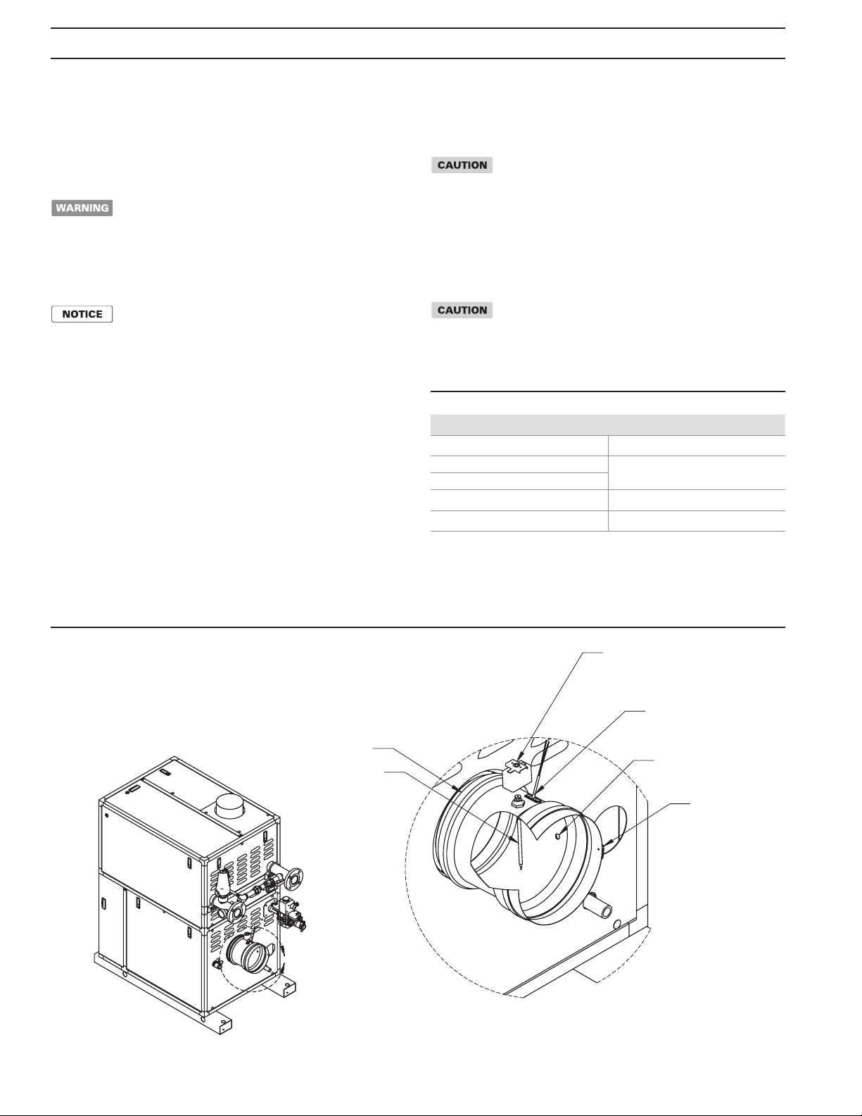
e PVC/CPVC vent adapter, (Figure 1), comes ed with a ue
temperature sensor and flue temperature high limit switch. This
system provides redundant over-temperature protection for the
PVC/CPVC vent system. e ue temperature sensor continuously
monitors the temperature of the ue gas exiting the Torus. If the
return water temperature exceeds 160°F the HeatNet Control, via
the ue temperature sensor, will recognize the resultant increase in
ue temperature and reduce the ring rate. Should the sensor fail, the
manual reset high limit switch will trip and shut down the Torus
before the ue temperature can exceed a safe limit.
e Torus vent collar connection point is accessible at the back of
the unit, (Figure 1). Carefully push the PVC/CPVC Vent Adapter
(1250-4000), into the ue outlet vent collar until it booms against
the stop bead on the adapter and tighten the ring clamp to secure the
vent adapter to the Torus vent collar.
PVC/CPVCVENT ADAPTOR INSTALLATION
ImproperinstallationofthePVC/CPVCventadaptorcan
cause pooling of corrosive condensate and result in
premature failure of the vent adaptor voiding the
manufacturer’s warranty!
WiththePVC/CPVCventadaptorpositionedattherearoftheunitcare-
fully insert the manual reset high limit through the ue pipe opening in
therearcabinetpanel.Mountthehigh limittothe economizerbracketas
shown in Figure 1.
Do not kink or damage the high limit capillary tube or the
limit may be ruined voiding the manufacturer’s warranty!
Position the vent adaptor so the high limit switch capillary is at the top of
the adaptor, Figure 1.
Table 1 PVC/CPVC Vent Adapter Kits
Figure 1 PVC/CPVC Vent Adapter
Model Size RBI Part Number*
1250 & 1500 (8"x6") 75-0553-001
1250 & 1500 (8"x8") 75-0553-002
2000 (8"x8")
2500 & 3000 (10"x10") 75-0553-003
4000 (12"x12") 75-0553-004
* Includes: adapter, Jumo high limit, HeatNet stack temperature
sensor, and misc. wiring.
A
DETAIL A
SCALE 1 : 6
BAND CLAMP
BAND CLAMP
ANALYZER FITTING
JUMO HIGH LIMIT
RIOM-0315_A
STACK SENSOR
HIGH LIMIT PROBE
Torus Optional PVC/CPVC Vent System Installation Instructions Supplement
3
PVC/CPVC VENT ADAPTOR WIRING
Failure to properly connect the uetemperature sensor
and ue temperature high limit switch will prevent the
Torus from operating.
Locate the wire harness inside the rear cabinet. Connect the two
wires with the 1/4 in/ft, 6.4 mm/m quick connects to the flue
temperature high limit switch. Connect the two wires with the 3/16
in, 4.8 mm quick connects to the ue temperature sensor.
PVC/CPVC VENT SYSTEM INSTALLATION
Neverinsulateor encapsulatethePVC/CPVCventsystem
oroverheatingandfailureofthe ventsystemmayoccur.e
PVC/CPVC vent system must be exposed to ambient air
andreadilyvisible forinspection.Failuretoproperlyventthis
productcanresultinCO poisoningcausingseverepersonal
injuryordeath!Exception:PerNFPA54Secion12.6.8:e
remaining space surrounding a chimney liner, gas vent,
special gas vent or plastic piping installed within a masonry
chimneyshall notbeused toventanother appliance.
e PVC/CPVC vent adapter has been engineered to directly accept
PVC/CPVC vent pipe. e internal gasket in the vent adaptor will form
a gas and water tight seal. No glues or sealants are required at this
connection.SlidetherequiredhorizontallengthofPVC/CPVCpipeinto
the vent adaptor and tighten the ring clamp to secure it in place. e vent
system must be sized per Table 2.
Table 2 Category IV Maximum Equivalent Vent Length
e maximum equivalent length for a positive pressure PVC/CPVC
vent system is as noted in Table 2. Each 90° elbow and the vent ter-
minal are equal to 10 linear , 3.0 linear m of pipe.
To maximize the performance of the vent system, locate 90° elbows
as far from the Torus and one another as possible.
When horizontal vent runs exceed 5 , 1.5 m they must be supported
at 3 , 0.91 m pitched intervals with overhead hangers. e ventsystem
mustbepitcheddown, towardtheventterminal,1/4 in/, 6.4 mm/m.
If the vent system contains vertical sections horizontal vent runs be-
tween the Torus and the vertical section must be pitched back, to-
ward the economizer, 1/4 in/, 6.4 mm/m, to prevent condensate
from pooling in the vent.
PVC/CPVC VENT PIPE PREPARATION
& ASSEMBLY
Only schedule 40 PVC/CPVC pipe sized per Table 1 is
to be used. e use of heavier wall pipe may prevent the
Torus from operating properly!
1. Cut pipe ends squarely and remove all burrs, ridges and foreign
maer using the appropriate tools and materials.
Failure to remove burrs or ridges will result in the cement
in the ing socket being scraped from the socket surface
producingadry jointwhich will havea high probabilityof
failure.
2. Before applying any cement dry t pipe and ings together to
ensure that the parts t properly.
3. Disassembledryedpartsandcleanthepipeandingsurfaces
to be joined with a PVC/CPVC cleaner. Surfaces to be joined
must be free of dirt, moisture, oil and other foreign maer.
All primers, cleaners and cements must meet all local
codes. Before using primers, cleaners and cements, stir or
shakewell, makingsurethecontentsareliquid. Donotuse
if found to be lumpy or in a jelly-like state. Do not add
solvents or thinners to reclaim thickened or lumpy
material.PrimersandcementshouldbeNSF and/orUPC
listed. Failure to use proper materials when venting this
product can result in CO poisoning causing severe
personal injury or death
Use of cellular core PVC (ASTM F891), cellular core
CPVC,orRadel (polyphenolsulfone)in ventingsystems
shall be prohibited.
Coveringnon-metallicventpipeandingswith thermal
insulation shall be prohibited.
Primers, cleaners and cements are extremely ammable
and harmful or fatal if swallowed. Always store primers,
cleaners and cements in a cool, dry, well ventilated place.
Do not store them near heat, sparks or flames. Keep
containers closed when not in use. Wear impervious
clothingwhile handling.Donot smoke,eatordrinkwhile
handlingprimers,cleanersandcements.Wash thoroughly
after handling and before eating. Wear eye protection
when handling. The harmful vapors can be absorbed
through the skin and may irritate eyes and skin. If inhaled,
getfreshairandseekmedicalaentionifillfeelingspersist.
Incaseof eyeand/or skin contact, immediately ushwith
plenty ofwaterfor 15minutesand seekmedicalaention
if irritation persists. If swallowed, drink water, do not
induce vomiting and call a physician or poison control
center immediately. Failure to read and observe all safety
information printed on primer, cleaner and cement
containers can result in severe personal injury or death!
Cleaners and primersareintendedfor dierentfunctions
and should not be considered inter-changeable. Verify
with ventmaterial manufacturerforspecic requirements.
4. Apply a coatofprimertothepipeandingsurfacesthatwill
be joined.
5. Applyathincoatofcementtotheingsurfacethatwillbejoined
makingsurenotoverapplythecementwhichcancausepuddling
inside the ing.
6. Applyaliberalcoatofcementtothepipesurfacethatwillbejoined
making sure to completely coat the area so it is free of voids.
7. QUICKLY assemble the parts while the cement is uid! If the
cement dries before the parts are assembled, re-coat the surfaces
with cement then assemble them.
Model Size Outlet Diameter Max Equiv. Length
In In
1250 6 40
8 90
1500 6 40
8 90
2000 8 90
2500 & 3000 10 90
4000 12 90

8. Push the end of the pipe completely into the ing socket so
it booms out and rotate the ing or pipe at least 1/4 turn
to achieve proper cement spread. Make sure the parts are in
the correct orientation before the cement cures. e cement
bonds by melting the PVC/CPVC so once the joint is made
it cannot be disassembled.
9. Hold the pipe and ing for 30 seconds to allow the joint to
suciently cure then carefully clean o any excess cement
with a cloth.
10. FollowthePVC/CPVCcementmanufacturer’sinstructions
toallowtheconnectionssucienttimetocurebeforepuing
any stress on the joint.
PVC/CPVC VENT TERMINALS
When vented horizontally the vent and air intake systems may be
terminated using standard PVC/CPVC ings with 1/4 in stainless
steel bird-screen inserts as shown below. e minimum distance from
the wall must be maintained as shown in the Figures below.
Figure 2 Horizontal PVC/CPVC TEE Terminal
Figure 3 Horizontal PVC/CPVC 45° Elbow Terminal
Figure 4 Horizontal PVC/CPVC 90° Elbow Terminal
Figure 5 Horizontal PVC/CPVC Coupling Terminal
Figure 6 Vertical PVC/CPVC Terminal
e input of the unit must be set per Table 3 or nuisance shutdowns
may occur under strong wind conditions.
Table 3 Turn Down vs Combustion Air Source
When vented vertically the vent and air intake systems should be
terminated using standard 45° and 90° PVC/CPVC Elbow ings
with a 1/4 in stainless steel bird-screen insert as shown below.
e rest of the applicable Combustion Air & Ventilation and Venting
instructions contained in the INSTALLATION & OPETION
MANUAL MUST BE FOLLOWED.
10'' Min
1/4'' SS Bird Screen
In Opening
8'' Min
1/4'' SS Bird Screen
In Openings
8'' Min
1/4'' SS Bird Screen
In Openings
10'' Min
1/4'' SS Bird Screen
In Opening
1/4'' SS Bird Screen
In Opening
Exhaust Combustion Air Turn Down Ratio
Vent Terminal Indoor 3:1
Outdoor 5:1
Copyright 2008 Mestek, Inc.
260 North Elm Street 7555 Tranmere Drive
Westeld, MA 01085 Mississauga, Ontario L5S 1L4 Canada
Phone: (833) 265-5371 Phone: (905) 670-5888
Fax: (413) 568-9613 Fax: (905) 670-5782
www.rbiwaterheaters.com
This manual suits for next models
5


