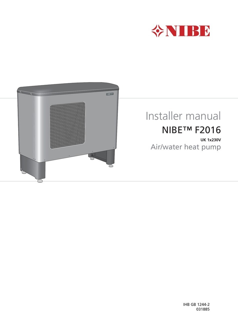
Mestek HP 0275 Series Quick guide

Commercial
Heat Pump
Inverter Air-to-Water
HP Series 0275
Installation and
Instruction Manual
HP-IOM-1
260 North Elm Street 7555 Tranmere Drive
Westeld, MA 01085 Mississauga, Ontario L5S 1L4 Canada
Phone: (413) 564-5540 Phone: (905) 670-5888
www.mestek.com

– 2 –
Commercial Heat Pump - Inverter Air-to-Water
Hazard Definitions
The following terms are used throughout this manual to bring
attention to the presence of potential hazards or to important
information concerning the product.
Indicates an imminently hazardous situation, which
if not avoided, WILL result in death, serious injury or
substantial property damage.
Indicates an imminently hazardous situation, which
if not avoided, COULD result in death, serious injury
or substantial property damage.
Indicates an imminently hazardous situation, which
if not avoided, MAY result in minor injury or property
damage.
Used to notify of special instructions on installation,
operation or maintenance, which are important to
equipment, but not related to personal injury hazards.
HP General Information
The HP Series air-to-water heat pump provides building owners
with an all electric, environmentally friendly alternative to boilers
for their low temp heating applications while also being able to
reverse cycle and provide hydronic cooling.
The HP Series utilizes advanced EVI (Enhaced Vapor Injection)
technology, an intelligent controls system and R410a refrigerant
to produce water temperatures up to 140°F in ambient
temperatures as low as -20°F. This allows for complete flexibility
in most climates while maintaining efficiencies that benefit the
end user. The inverter compressor technology provides a precise
control of capacities allowing for load matching throughout the
range of the product and eliminating wasteful usage of energy
in a typical on/off compressor unit.
Low Ambient Temperature Cooling Operation
If cooling operation is desired in a year-round application, or any
time outdoor temperatures are expected to be consistently below
55˚F, the fan operation should be modied in order to ensure
proper operating conditions within the refrigeration system.
Read Before Proceeding
■ In order to provide the customers with high quality, strong
reliability and good versatility in a product, this heat pump
is produced by strict design and manufacturing standards.
This manual includes all the necessary information about
installation, troubleshooting, and maintenance.
Please read this manual carefully before you open or maintain
the unit. The manufacturer of this product will not be held
responsible if someone is injured or the unit is damaged, as a
result of improper installation, troubleshooting, unnecessary
maintenance which is not described in this manual.
The unit must be installed by a licensed, qualied installer.
■ It is vital that the below instructions are adhered to at all
times to uphold the warranty.
– The unit can only be opened or repaired by qualied
installer or an authorized dealer.
– Maintenance and operation must be carried out according
to the recommended time and frequency, as stated in this
manual.
– Use genuine standard replacement parts only.
Failure to comply with these recommendations will void the
warranty.
■ Inverter air-to-water heat pump is high efcient, energy saving
and environment friendly, which is mainly used for space
heating/cooling and some DHW applications where needed.

– 3 –
Commercial Heat Pump - Inverter Air-to-Water
Specifications
Table 1 Specication Data
Heating
Hz Water T (°F) Ambient (°F) Capacity (btu/hr) Power (kW) COP
90
100
-20 145,242 21.13 2.01
-4 173,960 21.31 2.39
17 211,215 21.73 2.85
47 322,135 23.28 4.05
120
-20 129,954 25.21 1.51
-4 155,648 25.42 1.79
17 188,981 25.92 2.14
47 288,226 27.77 3.04
140
-20
-4 137,337 28.79 1.4
17 166,748 29.36 1.66
47 254,317 31.46 2.37
60
100
-20 98,888 21.13 1.67
-4 118,441 21.31 1.98
17 143,806 21.73 2.42
47 213,626 23.28 3.65
120
-20 88,479 25.21 1.25
-4 105,973 25.42 1.48
17 128,668 25.92 1.82
47 191,139 27.77 2.74
140
-20
-4 93,506 28.79 1.16
17 113,531 29.36 1.41
47 168,652 31.46 2.13
30
100
-20 47,899 10.57 1.33
-4 57,370 10.75 1.56
17 74,150 10.64 2.04
47 113,934 10.59 3.15
120
-20 42,857 12.61 1
-4 51,331 12.82 1.56
17 66,345 12.85 2.04
47 101,941 12.99 3.15
140
-20
-4 45,292 14.52 0.91
17 58,539 14.38 1.19
47 89,948 14.31 1.84
Choose the Correct Size Heat Pump
Perform appropriate load calculation to determine required heating or cooling load for the project. Refer to specifications in this
manual to determine proper size heat pump.
Table 2
HP0275
Heating*
Capacity Range Btu/hr 101,941-288,226
Power Input Range kW 13-28
Efciency COP Up to 3.04
Heating**
Capacity Range Btu/hr 188,981-66,345
Power Input Range kW 12.85-25.92
Efciency COP Up to 2.14
Cooling***
Capacity Range Btu/hr 129,661-203,681
Power Input Range kW 8.7-23
Efciency EER 2.5
IPLV**** EER 17.18
Refrigerant
Type R410a
Amount (Qty) lbs 20 (2)
Pressure (low) PSI 305
Pressure (high) PSI 638
Dimensions
Shipping (LxWxH) in 89 x 50 x 89
Unit (LxWxH) in 86 x 45 x 84
Weight lbs 1615
Electrical
Volts/Ph/hz 460/3/60
MCA Amps 60
MOPD Amps 70
Hydronic
Pressure Drop (@75GPM) PSI (ft/hd) 10 (23)
Connection In 4
Min Flow G.P.M. 44
Max Flow G.P.M. 75
Max System Pressure PSI 145
Water Connection In 4
Sound @ 3 meters dB(A) 67
Operating temps °F -20-120
* Heating (DB)@ 47°F, Delivered Water 120°F per AHRI 550-590 (75 GPM) EWT 110°F
** Heating (DB)@ 17°F, Delivered Water 120°F per AHRI 550-590 (75 GPM) EWT 110°F
***Cooling (DB/WB)@ 95°F/86°F, Delivered Water 44°F per AHRI 550/590 (60GPM) EWT 54°F
****IPLV is the recognized measurement of efciency for Integrated Part Load Values in accordance with AHRI 550/590.
Ambient temp = 95°F. Delivered Water = 44°F (44GPM)

– 4 –
Commercial Heat Pump - Inverter Air-to-Water
Specifications
Figure 1 Dimensions
DN65
Foot mounting dimensions: 63" x 43"
84"
Electrical box
23"
6.5"
24"
Water outlet
Water inlet
63"
86"
43" 46"
4 x
M12
Rubber feet
Mounting position
Installation
Transporting
During transportation, be sure that the unit is always standing up.
The unit shall not be laid on its side. Failure to keep upright can
damage components and void the product warranty.
If the unit needs to be lifted
by crane, please use cable
appropriate for the weight
of the unit and lifting points
located at the bottom of the
unit. Ensure the heat pump
is protected using protective
material between the cables
and the unit. This will prevent
any damage to the coil, fans
and cabinet. (see figure for
example)
Heat exchanger ns are sharp and can cut a nger
if handled improperly. Please handle with gloves or
protective wear.
protecto
r
hoist rope
handling hole
°06°0
4e
lgna
Installation Location
• Units can be installed outdoors as long as the location determined
can handle the weight (see specications) for each unit.
• The location is free from heat radiation and other possible re
hazards.
• There must be enough space around the unit for maintenance
see "Required Clearances". The base of the unit must be
located a minimum of 10 inches off the ground or above the
highest anticipated snow level to allow proper condensate
drainage. The condensate shall be provided a path to drain
before re-freezing in an area that could create an obstruction
or hazardous conditions such as on a walkway.
Figure 2

– 5 –
Commercial Heat Pump - Inverter Air-to-Water
Installation
Figure 3 Required Clearances (in)
Figure 4
40.040.0
40.0
40.0
40.0
60.0
10.
0
40.0
10.0
15.0
15.0
40.0
60.0
H
40.0+H 40.0+H
H
40.0
60.0
45°

– 6 –
Commercial Heat Pump - Inverter Air-to-Water
Glycol/Water System
Table 3 Glycol Concentrations (10% Minimum, 50% Maximum)
Propylene Glycol % 10 20 30 40 50
Min. Ambient Temp for Operation 26°F/-3°C 18°F/-8°C 8°F/-13°C -7°F/-22°C -29°F/-34°C
Capacity Multiplier 0.99 0.98 0.96 0.93 0.88
Pressure Drop Multiplier (Cooling) 1.10 1.20 1.34 1.5 1.65
Pressure Drop Multiplier (Heating) 1.10 1.20 1.34 1.46 1.5
Minimum Expansion Volume / System Volume
Heating and Cooling 1 gallon expansion per 15 gallons system volume
Heating only, HP only 1 gallon expansion per 20 gallons system volume
Heating only, with Boiler 1 gallon expansion per 15 gallons system volume
Glycol / Water Mixture
The water system must contain a mixture of
inhibited glycol and water with thermal protection
sufcient for the coldest expected temperature for
the installation. The inhibitor level can degrade over
time, and may need to be adjusted periodically.
The inhibitor is essential to prevent the glycol from
accelerating corrosion of metal components in the
system. The glycol and inhibitor levels must be
checked regularly (no less than once annually).
The minimum allowable concentration of glycol is
10% by volume in all installations.
Automotive glycol is not suitable for use in the
system. Over time it may leave deposits which will
degrade the performance and damage pumps or
other devices in the system. Use only propylene
glycol mixtures specically labeled for boiler or HVAC
use.
Obtain all components required for installation (piping, pumping
etc...) and make sure all components and piping comply with
applicable local codes. System uid expansion must be
calculated per established engineering methods.
DO NOT use galvanized pipe anywhere in the system.
Galvanizing will react with the glycol and can cause glycol
degradation and sludge in the system.
Insulate The Piping
1. After testing and draining the system, apply pipe insulation. Fill
system with glycol/water mixture. Calculate the system volume.
2. See Table 3, for required glycol concentration for the minimum
expected outside temperature.
3. Obtain the required volume inhibited glycol/water solution
premixed or mix in a clean container. (The glycol must contain
an inhibitor to prevent metal corrosion.)
4. Pump the glycol/water solution into the system, allowing air
to escape through the purge valve(s).
5. After lling the system, sample the system uid and verify
glycol and inhibitor percentages, following instructions
provided with the glycol.
Installation
Prior to Initial Startup
Before proceeding read and fully understand
the instructions contained in this manual. Do not
attempt to operate this heat pump if it has not been
installed in accordance with the guidelines set forth
in this manual. Failure to comply with this warning
can result in extensive property damage, severe
personal injury or death! Failure to comply can also
void product warranty.
Inspection before turning unit on;
• Check and make sure that the pipe connections are secured,
leak free and the appropriate valves are open.
• Check the water loop to ensure there is sufcient water inside
the expansion tank, the water loop is full of water/glycol mix*
and without any air. Also make sure there is good insulation for
the piping.
• Check all electrical wiring. Make sure that the power voltage
is normal, the wiring is completed per the diagram, and the
ground is connected.
• Ensure air-to-water heat pumps are free of any debris and that
all loose screws or parts have been secured. Once power is
turned on, check controller display for any immediate faults.
A licensed and qualied installer can also verify refrigerant
pressures by using the refrigerant ports located within the unit.
• The ow switch is installed inside of the heat pump. Check to
ensure that the wiring and action of the switch is normal and
controlled by the controller. Flow switch will open at 27 G.P.M.

– 7 –
Commercial Heat Pump - Inverter Air-to-Water
General Piping Requirements
Improper piping of this heat pump will void the
manufacturer’s warranty and can cause system
failure resulting in flooding and extensive property
damage!
Shut off valves and unions should be installed at
the inlet and outlet connections of the heat pump to
provide for isolation of the unit should servicing be
necessary.
Freeze Protection
Installations in areas where the danger of freezing exists are not
recommended unless proper freeze protection is provided. The
following precautions MUST be observed:
1. A continuous flow of water through the unit MUST be
maintained! The pump responsible for flow through the
heat pump must run continuously!
2. A polypropylene glycol/water mixture suitable for the minimum
temperature that the unit will be exposed to must be used. The
pump must be capable of producing a minimum of 15% more
ow and overcoming a 20% increase in head loss. Please refer
to glycol/water system of this manual for performance correction
factors and suggested glycol percentages for the heat pump
system.
3. If the unit must be shut off for any reason the electric and water
supplies MUST be shut off and the unit and its pump completely
drained.
System Piping
General Piping Requirements
All system piping must be installed by a qualied technician in
accordance with the latest revision of the ANSI/ASME Boiler and
Pressure Vessel Code, Section IV.
All applicable local codes and ordinances must also be followed.
A minimum clearance of 1in, 25 mm must be maintained between
system pipes and all combustible construction. All system piping
must be supported by suitable hangers, not the heat pump The
thermal expansion of the system must be considered when
supporting the system. A minimum system pressure of 20 psig,
138 kPa must be maintained at heat pump operating conditions.
For glycol systems, a minimum system pressure of 30 psig, 207
kPa must be maintained at system operating conditions.
System Cleaning & Flushing: Prior to commissioning
the heat pump, the piping/system must be cleaned and
ushed to prevent contaminants from settling back into
the heat pump and fouling the heat exchanger.
Isolate the heat pump from the system prior to the clean-
ing process. Fill the system with water, add the cleaning
solution and follow the solution manufacturer’s instruc-
tions. Once clean, rell the system with clean water as
specied in the Water Treatment section.

– 8 –
Commercial Heat Pump - Inverter Air-to-Water
Figure 5 Single Heat Pump Piping
Pump Requirements
This heat pump requires a continuous minimum water ow for
proper operation. The system pump must be sized to overcome
the head loss of the heat pump and the system in order to achieve
the required temperature rise. If the system contains hydronic
antifreeze this must be considered when sizing the pump.
Expansion Tank & Air Separator
An expansion tank or other means to control thermal expansion
must be installed in the system. An expansion tank must be
installed close to the heat pump on the suction side of the pump.
An air scoop and automatic air vent must also be installed to
eliminate air trapped in the system.
Reverse Return Piping (RECOMMENDED)
Systems using multiple heat pumps can also be installed using
a reverse return system, see piping schematics in this manual.
Primary/Secondary Piping
Although acceptable, the system is not as cost effective as
reverse return piping. Piping schematics in this manual shows a
typical primary/secondary piping system. A dedicated pump is
used to maintain a constant water ow through the heat pump.
Flow must be properly accounted for in the design of primary/
secondary systems. In order to prevent heat pump(s) short
cycling the system ow must be equal to or higher than the heat
pump(s) local ow. Systems using multiple heat pumps can be
installed using a primary/secondary manifold system, see piping
schematics in this manual.
EXPANSION TANK
BACKFLOW-PREVENTIO
N
DEVICE
PRESSURE REDUCING
VALVE
VALVE
CIRCULATOR
HP (Model/Series)
OUTDOOR UNIT
SYSTEM RETURN
SUPPLY
WM SYSTEM
MAKE-UP
COLD WATER
WM WATER METER
INDOOR MECHANICAL SPACE
Water Treatment
This heat pump was designed to operate in a closed loop heating
system. System ll water must not contain more than 500 ppm of
total dissolved solids, less than 150 ppm chloride concentration
and no greater than 300 ppm hardness. Suspended solids such
as Magnetite, Iron Oxides must be ushed from the system prior
to commissioning the heat pump(s). The PH level must be within
the 6.5-10 range. Where required, the system must be protected
by the addition of a corrosion inhibitor per the chemical supplier’s
instructions.
For systems requiring glycol for freeze protection use a glycol/
water mix that prevents foaming. Air entrapped within foam
signicantly decreases heat transfer and can result in damage
to the heat exchanger. Products such as DOWFROST,
DOWTHERM, UCARTHERM or an equivalent product must be
used to ensure proper protection to the heat pump.
The water used for dilution of concentrated heat transfer uids
must be distilled, de-ionized, or equivalently clean as stated
above. De-ionized water by itself can be aggressive torwards
many metals, but is perfectly safe when used for dilution of
DOWFROST, DOWTHERM or UCARTHERM as specied by
the manufacturer.
FAILURE TO ENSURE PROPER WATER QUALITY CAN
RESULT IN DAMAGE TO THE HEAT PUMP(S) VOIDING THE
WARRANTY.
Water Meter
Make-up water introduced into a closed system due to system
leaks can negatively affect the long term reliability of the
heating sytem resulting in abnormal heat pump water quality. It
is recommended that a water meter be installed in the system
make-up line. If make-up is recorded, the leaks must be found
and repaired.

– 9 –
Commercial Heat Pump - Inverter Air-to-Water
Figure 8 Typical Multiple Heat Pump Primary/Secondary Piping
Figure 6 Typical Multiple Heat Pump Reverse Return Piping (RECOMMENDED)
Figure 7 Typical Single Heat Pump Primary/Secondary Piping
NOTE: Not all system valves may be shown. Consult local codes for additional system components which may be necessary.
NOTE: Not all system valves may be shown. Consult local codes for additional system components which may be necessary.
NOTE: Not all system valves may be shown. Consult local codes for additional system components which may be necessary.
AUTOMATIC AIR VENT
EXPANSION TANK
BACKFLOW-PREVENTION
DEVICE
PRESSURE REDUCING
VALVE
SHUT-OFF VALVE
CIRCULATOR
HP (Model/Series)
OUTDOOR UNITS
SYSTEM RETURN
SUPPLY
WM
SYSTEM
MAKE-UP
COLD WATER
WM WATER METER
INDOOR MECHANICAL SPACE
PRESSURE RELIEF VALVE
MOTORIZED BALL VALVE
M
M
AIR SEPARATOR
M
M
AUTOMATIC AIR VENT
EXPANSION TANK
BACKFLOW-PREVENTION
DEVICE
PRESSURE REDUCING
VALVE
SHUT-OFF VALVE
CIRCULATOR
HP (Model/Series)
OUTDOOR UNITS
SYSTEM RETURN
SUPPLY
WM
SYSTEM
MAKE-UP
COLD WATER
WM WATER METER
INDOOR MECHANICAL SPACE
PRESSURE RELIEF VALVE
MOTORIZED BALL VALVE
M
M
AIR SEPARATOR
M
M
AUTOMATIC AIR VENT
EXPANSION TANK
BACKFLOW-PREVENTION
DEVICE
PRESSURE REDUCING
VALVE
SHUT-OFF VALVE
CIRCULATOR
SYSTEM RETURN
SUPPLY
WM
SYSTEM
MAKE-UP
COLD WATER
WM WATER METER
INDOOR MECHANICAL SPACE
PRESSURE RELIEF VALVE
MOTORIZED BALL VALVE
M
AIR SEPARATOR
HP (Model/Series)
OUTDOOR UNIT
MIN 3 PIPE DIA
MAX 10 PIPE DIA
BETWEEN CENTERS
HP (Model/Series)
OUTDOOR UNITS
AUTOMATIC AIR VENT
EXPANSION TANK
BACKFLOW-PREVENTION
DEVICE
PRESSURE REDUCING
VALVE
SHUT-OFF VALVE
CIRCULATOR
SYSTEM RETURN
SUPPLY
WM
SYSTEM
MAKE-UP
COLD WATER
WM WATER METER
INDOOR MECHANICAL SPACE
PRESSURE RELIEF VALVE
AIR SEPARATOR
MIN 3 PIPE DIA
MAX 10 PIPE DIA
BETWEEN CENTERS
CHECK VALVE

– 10 –
Commercial Heat Pump - Inverter Air-to-Water
Electrical Wiring and Controls
Electrical Connections
• The power supply must go through the wire access and be
connected to the power supply terminals in the control box.
Then connect the 3-signal wire plugs of the wire controller and
main controller.
• External pump can be powered through main power terminals
accessed through main power access on side of the units.
• If an additional auxiliary heater is need to be controlled by the
heat pump controller, the relay (or power) of the aux-heater
must be connected to the relevant output of the controller.
• Power supply for the unit should follow unit electrical
specications and adhere to local and national electrical codes.
Electrical Power Connections
Label all wires prior to disconnection when servicing
controls. Wiring errors can cause improper and
dangerous operation! Verify proper operation after
servicing.
The electrical connections to this heat pump must be made in
accordance with all applicable local codes and the latest revision
of the National Electrical Code, ANSI /NFPA-70. Installation
should also conform with CSA C22.1 Canadian Electrical Code
Part I if installed in Canada. A separate circuit breaker must be
installed for the heat pump - (if required, the optional local pump
FLA must be incorporated and sized accordingly). A properly
rated shut-off switch should be located at the heat pump. The
heat pump must be grounded in accordance with the authority
having jurisdiction, or if none, the latest revision of the National
Electrical Code, ANSI/NFPA-70.
The electrical loads given in the Specication Table, allow for a
pump load of no more than 5 amps at 110 VAC (2.5 amps at 230
VAC). If the pump load exceeds this, provide a separate power
source to the pump.
Line voltage eld wiring of any controls or other devices must
use copper conductors with a minimum size of #14 awg.
Refer to point of connection diagram in this manual and the
wiring diagram supplied with the heat pump for proper wiring
connections.
Figure 9 Wiring Diagram
0123
456789
A
B
C
D
E
F
A
B
C
D
E
F
d
CODE:20200701-0001
L1
4V1
N
4V2
N
CH1
CH2
13
24
5
6
7
8
01
N
N
N
NN
R71
NN
N
N
N
R81
N
COMP1
89:
'ULYHUPRGXOH
ERDUG
89:
&7
A
B
GND
CN501
5('
:+7
%/.
1/ / %6$5
electric reactor
COMP2
89:
/
/
/
'ULYHUPRGXOH
ERDUG
89:
&7
A
B
GND
CN501
5('
1/ / %6$5
1,11
(0,᧤᧥
&,17%,16$,15
$2875ಬ%2876ಬ &2877ಬ12871ಬ
1,11
(0,᧤᧥
&,17%,16$,15
$2875ಬ%2876ಬ &2877ಬ12871ಬ
L1
L1
L2
L2
L3
L3
N
1
2-L3 2-L1
2-N
2-L2
/
/
/
1
1-L3 1-L1
1-N
1-L2
1-L1
1-L2
1-L3
1-N
2-L1
2-L2
2-L3
2-N
electric reactor
N
L2
L2
L3
3
3
3
3
41
40
FU7
315mA
FU8
315mA
L1
L1
HP25
N
CN501
1
N
28
/
89:
FAN1
B
A
GND
30
32
BRN
BLU
Y/G
/
CN501
1
N
29
/
89:
FAN2
B
A
GND
31
33
/
N-IN L-IN
EARTH
N-IN L-IN
EARTH
L3
8
9
:
8
9
:
4
1
N
1
26
45
220V
Electric
Heater
220V
Circulation
Pump
3
220V
Alarm
out
36
N
17 18 21 22 23 24 25 26 27
5V
19 20
5V15V25V35V4
12V-1 A1 B1 GND1
REDWHT YEL BLK
40
41
28 29 30 31 32 33
23 25 27
23 25 27
28
29
30
31
32
33
1478910
FS
11 12 13
78910 11 12 13 14
485A+
485B-
15 16
15 16
RED
WHT
BLU
BLK
Y/G
Remote
On/Off
Remote
Heat/Cool
Over Heat
protection
BRN
BLU
Y/G
BRN
BLU
Y/G
Controller
GND BLK
485B-
485A+
RED
12V
WHT
YEL
BRN
BLK
BLU
BRN
BLK
BLU
BRN
BLU
Y/G
L1
L2
L3
N
L1 L2 L3 N
TO POWER SUPPLY
440-460V/3N~/60HZ
CN1
RO 18
RO 17
RO 16
RO 15
RO 14
RO 13
RO 12
RO 11
RO 10
RO 09
RO 08
RO 07
RO 06
RO 05
RO 04
RO 03
RO 02
RO 01
L
N
AI/DI 32
AI/DI 28
AI/DI 27
AI/DI 26
AI/DI 25
AI/DI 24
AI/DI 23
AI/DI 22
AI/DI 21
AI/DI 20
AI/DI 19
AI/DI 17
AI/DI 16
AI/DI 15
AI/DI 14
AI/DI 13
AI/DI 12
AI/DI 11
AI/DI 10
AI/DI 09
GND
GND
GND
GND
GND
GND
GND
GND
GND
GND
GND
GND
GND
GND
GND
GND
GND
GND
GND
GND
GND
GND
GND
GND
GND
GND
GND
GND
GND
GND
GND
GND
GND
GND
GND
GND
GND
GND
PC1602
RO 19
RO 20
RO 21A
RO 21B
RO 22A
CN2
CN3CN5CN7
CN4CN6
CN8
AI/DI 04
AI/DI 03
AI/DI 02
GND
GND
GND
GND
GND
AI/DI 01
AI/DI 05
AI/DI 06
AI/DI 07
AI/DI 08
AI/DI 18
GND
AI/DI 29
AI/DI 30
AI/DI 31
AI/DI 33
AI/DI 34
AI/DI 35
AI/DI 36
AI/DI 37
AI/DI 38
AI/DI 39
AI/DI 40
AI/DI 41
AI/DI 42
AI/DI 43
AI/DI 44
GND
GND
GND
GND AI/DI 45
AI/DI 46
AI/DI 47
AI/DI 48
GND
GNDAI/DI 49
AI(50K) 50
GND
GND
GND
GND AI(50K) 51
AI(50K) 52
AI(50K) 53
AI(50K) 54
GND
GND
GND
GND AI(50K) 55
0-5V_IN01
GND
GND
GND
GND
GND
t
50K
ET1
t
50K
ET2
N
L1
LP1
RO 22B
RO 23
RO 24
0-5V_IN02
0-5V_IN03
0-5V_IN04
0-5V_IN05
0-5V_IN06
0-5V_IN07
0-5V_IN08
LP2HP1
JP15
N1L1
12V
12V
GND
485_A3
485_B3
JP13
485_B1
485_A1
485_B2
485_A2
GND
12V
GND
12V
JP2
GND
ZERO
GND
SPS
+12V
GND
ZERD
GND
L
N
5NC1PJ
L11N1
GND12V
16
15
12V-1
B1
A1
GND1
1
3
6
79
10 8
HP2
GND
GND
GND
GND
GND
GND
GND
0-10V_OUT1
+5V
0-10V_OUT2
+12V
JP12
5V
PWM_OUT2
PWM_OUT1
PWM_IN2
PWM_IN1
GND
3.3V
CN300
GND
IO
CLK
t
5K
OCT1
t
5K
EOT1
t
5K
t
5K
t
5K
OCT2
SUT2
EIT1
t
5K
t
5K
EIT2
EOT2
t
5K
ATSUT1
CT21
CT22
t
2K
t
2K
t
2K
t
2K
t
2K
t
2K
t
2K
t
2K
t
2K
OT IT
AFT1
AFT2 CT11
CT12
EVIV2
5
EVIV1
EEV22
5
EEV12
EEV21
EEV11
55
5
4V1
4V2
R7
R8
6.8K
6.8K
11
13
1214
Pressure sensor1
᧤SUT᧥Pressure sensor2
᧤SUT᧥
5V2
Pressure sensor1
᧤ET᧥
5V3
Pressure sensor2
᧤ET᧥
5V45859 57 GND
DNGDNG
GRYGRN NRGYRGDER REDGRYGRNRED
GRYGRNRED
5V1
57
58
59
GNDGND
GND
N
AFT:Anti-Freeze Temperature
AT:Ambient Temperature
COMP:Compressor
CH:Crankcase Heater
CT:Coil Temperature
EEV:Electronic Expansion Valve
ET:Exhaust Temperature
EIT:EVI Inlet gas temperature
EOT:EVI Outlet gas temperature
EVIV:Electronic Expansion Valve for EVI
FU:Fuse
FOHP:Fan-motor Overheat Protect
FS:Flow Switch
HP:High Pressure Protection
IT:Inlet Water Temperature
LP:Low Pressure Protection
OT:Outlet Water Temperature
OCT:Condenser outlet temperature
PH:Pan heater
Q:Air switch
SUT:Suction Temperature
SPS:Switching power supply
4V:4 Way Valve
5
:+7
%/.

– 11 –
Commercial Heat Pump - Inverter Air-to-Water
Figure 10 Controller Interface Diagram and Denition
30
5.Controlling and Operation
(2) Controller interface diagram and definition
GND 0-5V_IN8 63
0-5V_IN7 62
0-5V_IN6 61
0-5V_IN5 60
0-5V_IN4 59
0-5V_IN3 58
0-5V_IN2 57
0-5V_IN1 56
AI(50K) 54
AI(50K) 55
AI(50K) 53
AI(50K) 52
AI(50K) 51
AI(50K) 50
AI/DI 49
AI/DI 36
AI/DI 35
AI/DI 34
AI/DI 33
AI/DI 32
AI/DI 31
AI/DI 30
AI/DI 29
AI/DI 28
AI/DI 27
AI/DI 26
AI/DI 25
AI/DI 24
AI/DI 23
AI/DI 22
AI/DI 21
AI/DI 20
AI/DI 19
AI/DI 18
AI/DI 17
AI/DI 16
AI/DI 15
AI/DI 14
AI/DI 13
AI/DI 12
AI/DI 11
AI/DI 10
AI/DI 9
AI/DI 8
AI/DI 7
AI/DI 6
AI/DI 5
AI/DI 4
AI/DI 3
AI/DI 2
AI/DI 1
AI/DI 48
AI/DI 47
AI/DI 46
AI/DI 45
AI/DI 44
AI/DI 43
AI/DI 42
AI/DI 41
AI/DI 40
AI/DI 39
AI/DI 38
AI/DI 37
GND
GND
GND
GND
GND
GND
GND
GND
GND
GND
GND
GND
GND
GND
GND
GND
GND
GND
GND
GND
GND
GND
GND
GND
GND
GND
GND
GND
GND
GND
GND
GND
GND
GND
GND
GND
GND
GND
GND
GND
GND
GND
GND
GND
GND
GND
GND
GND
GND
GND
GND
GND
GND
GND
GND
GND
GND
GND
GND
GND
GND
GND
GND
GND
GND
GND
GND
GND
GND
GND
GND
GND
GND
GND
485_B2
485_A2
GND
485_B1
485_A1
12V
12V
GND
485_B3
485_A3
12V
CN5
12V
5V
0-10V_OUT2
0-10V_OUT1
PWM_OUT2
PWM_OUT1
PWM_IN2
64 0-5V IN9
65 0-5V IN10
66 0-5V IN11
PWM_IN1
CN6
CN7
CN2
3V3
GND
SIO
CLK
CN17
CN12 CN10
CN13 CN11CN15
CN16
⑤④③②①⑤④③②①⑤④③②①⑤④③②①
⑤④③②①⑤④③②①⑤④③②①⑤④③②①
CN14
PC1601
FUSE
T5AL/250VAC
67 0-5V IN12
OUT24
OUT23
OUT22B
OUT22A
OUT21B
OUT21A
OUT20
OUT19
OUT18
OUT17
OUT16
OUT15
OUT14
OUT13
OUT12
OUT11
OUT10
OUT9
OUT8
OUT7
OUT6
OUT5
OUT4
OUT3
OUT2
OUT1
L
N
LED light
JP3
Electrical Wiring and Controls

– 12 –
Commercial Heat Pump - Inverter Air-to-Water
Table 4 The Input and Output Interface Instructions
31
5.Controlling and Operation
(3) The input and output interface instructions
No. No.Sign SignMeaning Meaning
1
2
3
4
5
6
7
8
9
10
11
12
13
14
15
16
17
18
19
20
21
22
23
24
25
26
27
28
AI/DI1
AI/DI2
AI/DI3
AI/DI4
AI/DI5
AI/DI6
AI/DI7
AI/DI8
AI/DI9
AI/DI10
AI/DI11
AI/DI12
AI/DI13
AI/DI14
AI/DI15
AI/DI16
AI/DI17
AI/DI18
AI/DI19
AI/DI20
AI/DI21
AI/DI22
AI/DI23
AI/DI24
AI/DI25
AI/DI26
AI/DI27
AI/DI28
Water inlet temperature
Water outlet temperature
System 1 antifreeze temperature
System 1 coil temperature 1
System 1 coil temperature 2
System 2 antifreeze temperature
Ambient temperature
System 1 coil outlet temperature
System 1 return air temperature
System 2 coil outlet temperature
System 2 return air temperature
System 1 EVI inlet temperature
System 1 EVI outlet temperature
System 2 EVI inlet temperature
System 2 EVI outlet temperature
Water tank temperature
End return water temperature
System 2 coil temperature 1
System 2 coil temperature 2
No use
No use
No use
No use
No use
No use
No use
No use
No use
29
30
31
32
33
34
35
36
37
38
39
40
41
42
43
44
45
46
47
48
49
50
51
52
53
54
55
56
AI/DI29
AI/DI30
AI/DI31
AI/DI31
AI/DI33
AI/DI34
AI/DI35
AI/DI36
AI/DI37
AI/DI38
AI/DI39
AI/DI40
AI/DI41
AI/DI42
AI/DI43
AI/DI44
AI/DI45
AI/DI46
AI/DI47
AI/DI48
AI/DI49
AI 50(50K)
AI 51(50K)
AI 52(50K)
AI 53(50K)
AI 54(50K)
AI 55(50K)
0-5V_IN1
No use
No use
No use
No use
No use
No use
No use
No use
System 1 low pressure switch
System 2 low pressure switch
System 1 high pressure switch
System 2 high pressure switch
No use
No use
Water flow switch
Electric heating overload protection switch
Emergency switch
Mode switch
Fan 1 overload protection switch
Fan 2 overload protection switch
Reserved
System 1 exhaust temperature
System 2 exhaust temperature
No use
No use
No use
No use
System 1 low pressure sensor

– 13 –
Commercial Heat Pump - Inverter Air-to-Water
Table 4 The Input and Output Interface Instructions
32
5.Controlling and Operation
No. No.Sign SignMeaning Meaning
57
58
59
60
61
62
63
64
65
66
67
68
69
70
71
72
73
74
75
76
77
78
79
80
81
82
83
84
85
AI/0-5V_IN2
0-5V_IN3
0-5V_IN4
0-5V_IN5
0-5V_IN6
0-5V_IN7
0-5V_IN8
0-5V_IN9
0-5V_IN10
0-5V_IN11
0-5V_IN12
PWM_IN1
PWM_IN2
PWM_OUT1
PWM_OUT2
0-10V_OUT1
0-10V_OUT2
+5V
+12V
CN5
CN6
CN7
CN10
CN11
CN12
CN13
CN14
CN15
CN16
System 2 low pressure sensor
System 1 high pressure sensor
System 2 high pressure sensor
No use
No use
No use
No use
No use
No use
No use
No use
Flow meter
No use
No use
No use
No use
No use
No use
12V output
Wire controlled color display
Centrally controlled color display
DTU module
System 1 electronic expansion valve (big)
System 2 electronic expansion valve (big)
System 1 electronic expansion valve (small)
System 2 electronic expansion valve (small)
System 1 EVI electronic expansion valve
System 2 EVI electronic expansion valve
No use
86
87
88
89
90
91
92
93
94
95
96
97
98
99
100
101
102
103
104
105
106
107
108
109
110
111
112
CN17
OUT1
OUT2
OUT3
OUT4
OUT5
OUT6
OUT7
OUT8
OUT9
OUT10
OUT11
OUT12
OUT13
OUT14
OUT15
OUT16
OUT17
OUT18
OUT19
OUT20
OUT21A
OUT21B
OUT22A
OUT22B
OUT23
OUT24
No use
System 1 fan output (low speed)
System 1 fan output (high speed)
System 2 fan output (low speed)
System 2 fan output (high speed)
System 1 four-way valve output
System 2 four-way valve output
System 1 crankshaft heating belt output
System 2 crankshaft heating belt output
System 1 spray valve output (No use)
System 2 spray valve output (No use)
Water replenishing valve (reserved)
Backwater valve (reserved)
Water supply pump (reserved)
Electric heating
Circulating water pump output
Alarm output
System 1 fan output (high speed)
System 2 fan output (high speed)
No use
No use
No use
No use
No use
No use
No use
No use

– 14 –
Commercial Heat Pump - Inverter Air-to-Water
131°F
Heating
95°F
110°F
Controls and Operation
Every heat pump is shipped with a wired touch screen controller.
The controller should be mounted in an area safe from debris or
potential for damage and mounted securely.
Startup Screen
Home Screen in "Off" Mode
78°F
78°F 87°F
82°F

– 15 –
Commercial Heat Pump - Inverter Air-to-Water
45°F
Controls and Operation
Home Screen in "On" Mode
Table 5 Button Function
78°F
104°F
82°F
100
°F
12
7 8 9 10
11
1
1
2
3
4
5
6
4
5
6
2
3
13 14 15 16 17 18 19

– 16 –
Commercial Heat Pump - Inverter Air-to-Water
Controls and Operation
⑩
11
12
13
14
15
16
17
18
19
⑨
No. Icon Description
Indicating the operating status:
blue--cooling mode; red-heating mode; grey-power-off mode.
Indicating the target temperature of inlet water
Indicating the date and time
Indicating the ambient temperature
Indicating the Temp Timer function is activated
Indicating that the mute mode is activated
Indicating that the defrost mode is activated
Indicating that the electric auxiliary heating mode is activated
Indicating that the power timer mode is activated
Indicating the lock screen status
Fault icon indicating a fault has occurred. Fault icon will blink
during a fault and be removed when the fault is cleared.
Display circle
Table 6 Running Status Icons Description
9
10
11
12
13
14
15
16
17
18
19
7
8

– 17 –
Commercial Heat Pump - Inverter Air-to-Water
Controls and Operation
Button function
No. Name Function
Temp Timer
Power Timer
Mute Timer
Press to enter temp timer settings. Here you can set the
schedule and timer based on specific building requirements.
Press to enter power timer screen. Here you can set timers
to shut the unit down or turn the unit on with timers
Press to enter the mute timer screen. This allows the unit
to ignore/override the timer settings.
20
21
22
20 Fig. 4 Timer interface
Fig. 5 Temp timer interface
21 22
24
23
25
Timer Functions
Button Function
22
70°F
78°F
21
20
20
24
21
25
23
22

– 18 –
Commercial Heat Pump - Inverter Air-to-Water
Controls and Operation
The temp timer function allows timers to be set for on or off peak based on each application. First access the temp timer menu (20).
Press the cooling or heating (23) to set the mode required, then enter the start/end and setpoints (24). Last press on or off (25) to
enable or disable these timers.
Note: green: enable; grey: not enabled.
Power Timer
The power timer feature allows the user to set daily time parameters for the unit. To navigate to the power timer screen press power
timer (20). Select the specific day of the week (26), time (28) and AM or PM (27). Once finalized turn on or off (29) to enable or
disable.
Note: green: enable; grey: not enable.
Power Timer function allows you to set the opening time of the unit for each day of
the week, while this function is enable, the main interface displays “ ”.
To enalbe Power Timer function, firstly press Timer button ⑤in the main
interface, secondly press Power Timer button (Fig.4), it jumps to Power timer
interface (Fig.6), press to select the day of the week, press to select AM or
PM, then press to select the time, and lastly press to enable or turn off the
setting.
Temp Timer function means time-sharing temperature control, which is two
segments of staggered peak temperature control, and the target temperature of
two segments of different time periods can be set according to different modes.
When the system time enters the staggered peak time and the time-sharing
temperature control function is enabled, the main interface displays “ ”.
To enalbe Temp Timer function, firstly press Timer button ⑤in the main inter-
face, secondly press Temp Timer button (Fig.4), it jumps to Temp timer
interface (Fig.5), press to select the cooling or heating mode, then enter the
starting, ending time and target temperature setpoint value , and lastly press
to enable or turn off the setting.
20
21
26
28 29
27
20
Fig. 6 Power timer interface
23
24
24
26
Power Timer
28 27
29
Note: green: enable; grey: not enable.
Note: green: enable; grey: not enable.
5.Controlling and Operation
27
29
26
28

– 19 –
Commercial Heat Pump - Inverter Air-to-Water
Controls and Operation
Mute Timer
The mute timer function allows the user to disable/override any
timers that are in place. Once selected the screen will display
this symbol.
Settings
Table 7 Button Description (see below for details on each)
(6) Setting function
21
Fig. 7-1 Setting interface
Fig. 7-2 Setting interface
Mute Timer
30
To enalbe Mute Timer function, firstly press Timer button ⑤in the main inter-
face, secondly press Mute Timer button (Fig.4), it jumps to Mute Timer
interface, enter the start and end timer, and lastly press on/off button to enable
or turn off the setting. When the Mute Timer function is enable, the main inter-
face displays “ ”.
22
Note: if the unit without Mute Timer function, the operation is not available.
34 35 36
31 32 33
Page left
Page
right
5.Controlling and Operation
30 31 32 33
Page right
Page left
34 35 36
Fig.8-1 Running Status interface Fig.8-2 Unit Status interface
No. Name Function
Status
Parameter
Fault
Time
Temp Curve
Electric Heating
Fast Mute
30
31
32
33
34
35
36
Press to enter status menu.
Press and enter "22" to view/change installer accessible
parameters
Press to see current faults or history of faults
Press to set time and date of unit.
Press to see recent water temps and curves
Enable or disable ability to power electric heater
Enable or disable fast mute
30
31
32
34
35
36
33

– 20 –
Commercial Heat Pump - Inverter Air-to-Water
Controls and Operation
Status Button
By pressing the "status" button the installer will be able to view
the current running status of the unit and the status of many of
the units components and functions.
Running Status button shows current power mode (on/off) of the
unit, outlet and inlet water temperature and ambient temperature.
The unit status button allows access to specic menus involved
with the status of the unit. The installer password is '22'. The top/
sub menus are "Load" "Switch" "Temp" "Unit Info" "Inverter".
Load
This menu allows access to the current status of compressors,
fans, circ pump, 4-way valves electric heater, crankshaft heaters,
spray valves, fault alarms, chassis heater, EEV valve steps, and
capacity demands.
Switch
This menu allows access to the the current status of the high and low
pressure switches (each system), water ow switch, emergency input
switch, if the mode switch is open or closed, electric heater overload
switch, and each fan protection overload switches.
Temp
This menu allows access to the current status of the following
temperature readings:
Inlet Water
Outlet Water
Sys1 & 2 Antifreeze
Ambient Temp
Sys1 & 2 coil outlet temp
Sys 1 & 2 Suction temp
Sys 1 & 2 coil temps (1 & 2 temperatures)
Sys 1& 2 evap temp
Sys 1 & 2 superheat
Sys 1& 2 EVI (in temp)
Sys 1 & 2 EVI (out temp)
Sys 1 & 2 Exhaust temp
Sys 1 & 2 condensate temp
Sys 1 & 2 high and low pressure temp
Current running water ow (m3/hr)
Fig.8-1 Running Status interface Fig.8-2 Unit Status interface
No. Name Function
Status
Parameter
Fault
Time
Temp Curve
Electric Heating
Fast Mute
30
31
32
33
34
35
36
Press to enter status menu.
Press and enter "22" to view/change installer accessible
parameters
Press to see current faults or history of faults
Press to set time and date of unit.
Press to see recent water temps and curves
Enable or disable ability to power electric heater
Enable or disable fast mute
116°F
120°F
86°F
Unit Info
This menu allows access to the specic details to that units
software code, and software version for the main board, wired
controller, and each inverter boards.
Inverter
This menu allows access to the current status of the following
items related to the compressor and fan inverter boards.
Sys 1 & 2 Compressor set frequency
Sys 1 & 2 Compressor running frequency
System 1 & 2 Inverter phase current
Sys 1 & 2 Inverter board temp
Sys 1 & 2 Inverter bus voltage
Sys 1 & 2 If one or two inverter boards are running.
Sys 1 & 2 If there is a fault on either inverter board
Sys 1 & 2 Fan set speed
Sys 1 & 2 Fan running speed
Sys 1 & 2 Fan phase current
Sys 1 & 2 Fan IPM temp
Sys 1 & 2 Fan bus voltage
Sys 1 & 2 Fan faults
Table of contents
Other Mestek Heat Pump manuals
Popular Heat Pump manuals by other brands
Panasonic
Panasonic LIAC7IM3 operating instructions
Albixon
Albixon INVERBOOST PX user manual

Ouellet
Ouellet SED09KCH17S owner's manual

Vaillant
Vaillant aroSTOR VWL B 200/5 UK Installation and maintenance instructions
STIEBEL ELTRON
STIEBEL ELTRON WPL 34 Operation and installation

evoheat
evoheat CS Installation & operation manual
auer
auer HRC 70 PILOT-PREMIUM Installation and operating instructions
Vaillant
Vaillant VWZ 30/2 SV installation manual

Carrier
Carrier Deluxe 38YZA Installation and start-up instructions

York
York E*FH018 installation instructions

Carrier
Carrier 38YH Product data
Panasonic
Panasonic S*C09*3E8 Series installation manual

