6
Filter Dryer Installation — A filter dryer is
provided with PS series models only and must
be installed in the liquid line of the system. If the
installation replaces a system with a filter dryer
already present in the liquid line, the filter dryer
must be replaced with the one supplied with the
unit. The filter dryer must be installed in strict
accordance with the manufacturer’s installation
instructions.
For all other series models, installing a filter
dryer is optional. However, it is good installation
practice to install a filter dryer when replacing
the evaporator and/or condenser of a system.
When installing, the filter dryer must be installed
in strict accordance with the manufacturer’s
installation instructions.
Optional Equipment — Optional equipment
(e.g.: liquid line solenoid valves, etc.) should be
installed in strict accordance with the manufac-
turer’s installation instructions.
For refrigerant line sets that incorporate single
shot couplings only:
1. Remove protective caps from the unit and
the refrigerant line couplings.
2. Carefully wipe all coupling threads and
seals with a clean cloth to remove any dust
or foreign material which could contaminate
the refrigerant system.
3. Using refrigerant oil, lightly lubricate the
diaphragm, seal and threads on the male
unit coupling.
4. Connect couplings as follows:
Note: Start with indoor section first.
a. HOLD REFRIGERANT LINE IN
STRAIGHT POSITION TO UNIT
COUPLING AND THREAD COUPLING
HALVES TOGETHER BY HAND TO
INSURE PROPER CONNECTION.Hold
body of the line coupling hex with wrench,
while slowly tightening the union nut until
a definite resistance (bottoming out) is
felt.
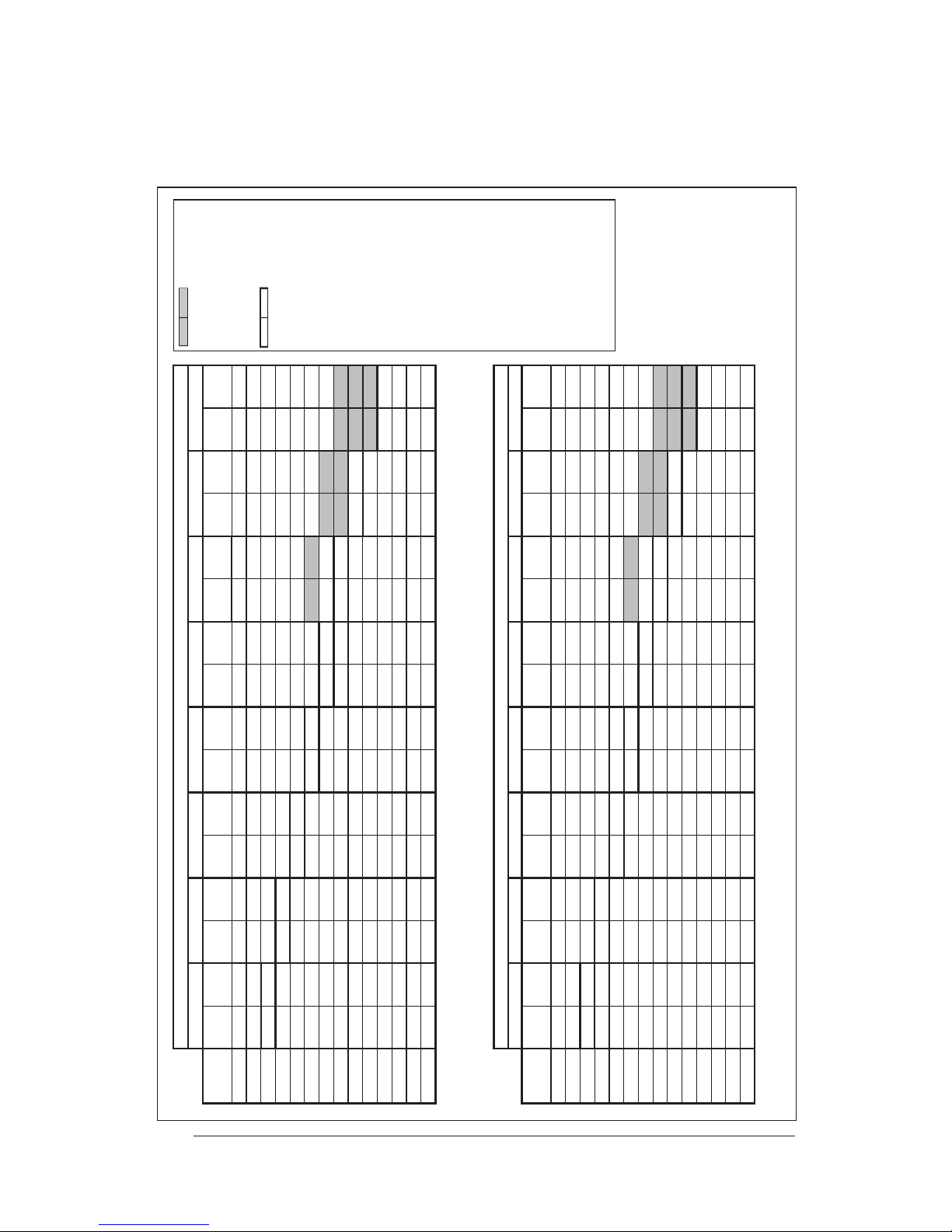
b. Mark the position of union nut (match
lines on the line coupling and the unit
bulk head), and then tighten the coupling
an additional 1/4 turn to insure leak-proof
connection. (See Table of Torque Values
for recommended torque values if a torque
wrench is used.)
Cantilever Mount — The cantilever mount
should be designed with adequate safety factor
to support the weight of the equipment, and for
loads subjected to the mount during operation.
Installed equipment should be adequately
secured to the cantilever mount and levelled
prior to operation of the equipment.
Roof Mount — The method of mounting should
be designed so as not to overload roof structures
nor transmit noise to the interior of the structure.
Refrigerant and electrical line should be routed
through suitably waterproofed openings to
prevent water leaking into the structure.
INSTALLING THE INDOOR UNIT
The indoor section should be installed before
proceeding with routing of refrigerant piping.
Consult the Installation Instructions of the indoor
unit (i.e.: air handler, furnace, etc.) for details
regarding installation.
CONNECTING REFRIGERANT
TUBING BETWEEN THE INDOOR
AND OUTDOOR UNIT
General — Once outdoor and indoor unit
placement hasbeen determined, route refrigerant
tubing between the equipment in accordance with
sound installation practices. Refrigerant tubing
should be routed in a manner that minimizes the
length of tubing and the number of bends in the
tubing. Refrigerant tubing should be supported
in a manner that the tubing will not vibrate or
abrade during system operation. Tubing should
be kept clean of foreign debris during installation
and installation of a liquid line filter drier is
recommended if cleanliness or adequacy of
system evacuation is unknown or compromised.
Every effort should be made by the installer
to ensure that the field installed, refrigerant
containing components of the system have been
installed in accordance with these instructions
and sound installation practices so as to insure
reliable system operation and longevity.
The maximum recommended interconnecting
refrigerant line length is 75 feet, and the
vertical elevation difference between the indoor
and outdoor sections should not exceed 20
feet. Consult long line application guide for
installations in excess of these limits.