020D-9800 REV A Page 9
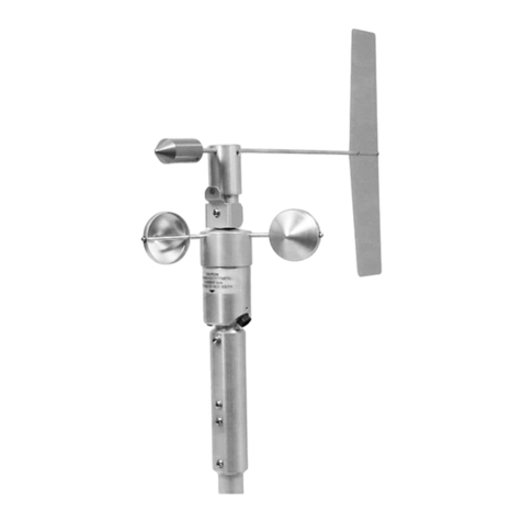
4.3 020D Wind direction Sensor Maintenance (Refer to 020D drawing for assembly
information)
The following procedures require a relatively clean, dry work area, a source of 12
VDC power at approximately 20 mA, a Model 040 Degree Wheel, and a 4-1/2 digit or
better digital voltmeter.
4.4 020D Wind Sensor Calibration
Any time the bearing, shaft, hub or potentiometer is removed and replaced, the
alignment of the potentiometer must be reestablished. Perform the following steps
for calibration:
A. Connect the sensor to a 12-volt power supply:
Pin A +12V
Pin B Common
B. Connect a high impedance digital (4-1/2 digit or better, see above) voltmeter
between common and Pin C (signal output).
C. Slide the Model 040 Degree Wheel onto the column of the wind direction sensor.
Install the 040 Pointer Assembly onto the rotating hub. Tape sensor hub and
column together so that the notches on both parts are exactly aligned.
D. Slide the degree wheel up to the pointer, allowing clearance space, and rotate
the degree wheel until the pointer is at exactly 180 on the wheel. Tighten the
degree wheel to the column, checking to ensure that it does not interfere with the
rotation of the pointer.
E. Remove tape and rotate the pointer, then recheck the alignment of the two
notches with the 180 mark on the degree wheel. Readjust if necessary.
F. Loosen the set screws in the shaft coupler (#21).
G. Place the pointer at 180 and rotate the potentiometer shaft coupler so that an
output of 2.500 0.005V (1.250V with a 2.5V output range) is measured. Tighten
set screws in the drive coupler (#21) and recheck at 180. Readjust if necessary.
H. Reconnect digital voltmeter to Pin C of the sensor connector and rotate the
pointer to 180. The output reading should be 2.500V 40mV (1.25V 20mV with
2.5V output range).
I. Remove 040 Degree Wheel and pointer. This completes the alignment
procedure.
