Metal-Fach ecoMAX860P TOUCH User manual

Boiler controller
ecoMAX860P TOUCH
FOR AUTOMATIC SOLID FUEL FIRED BOILERS WITH INGITION
(GUTTER AND RETORT FEEDERS), execution: ecoMAX920P1-T
INSTRUCTION INSTALLATION AND OPERATING MANUAL
ISSUE: 1.0
APPLIES TO SOFTWARE:
MODULE A
PANEL
v01.XX.XX
v.01.XX.XX
ecoSTER TOUCH**
ecoNET300**
functions available in the
additional module B
** room panel ecoSTER TOUCH and internet module ecoNET300 - not the standard equipment of the
controller.
02-2017
ecoNET.apk
www.econet24.com


TABLE OF CONTENTS
1 SAFETY REQUIREMENTS ..................................... 4
2 GENERAL INFORMATION .................................... 5
3 INFORMATION ABOUT DOCUMENTATION......... 5
4 STORAGE OF DOCUMENTATION......................... 5
5 APPLIED SYMBOLS .............................................. 5
6 DIRECTIVE WEEE 2012/19/UE............................. 5
INSTRUCTION MANUAL ............................................... 7
7 STRUCTURE –MAIN MENU................................. 8
8 OPERATING THE REGULATOR ............................. 9
8.1 DESCRIPTION OF DISPLAY MAIN WINDOW ................. 9
8.2 SWITCHING ON/OFF THE BOILER............................ 10
8.3 SETTINGS PRESET TEMPERATURE..................... 10
8.4 FIRING UP...................................................... 10
8.5 OPERATION ....................................................... 10
8.6 REGULATION MODE.......................................... 10
8.7 SUPERVISION ................................................ 11
8.8 BURNING OFF................................................ 11
8.9 STANDSTILL ................................................... 11
8.10 DOMESTIC HOT WATER SETTINGS HUW................. 11
8.11 SETTING HUW PRESET TEMPERATURE................... 12
8.12 HUW CONTAINER HYSTERESIS.............................. 12
8.13 HUW CIRCULATION ........................................... 12
8.14 ENABLING THE SUMMER FUNCTION .................... 12
8.15 DISINFECTION HUW CONTAINER .......................... 12
8.16 MIXER CIRCUITS SETTINGS ................................... 12
8.17 WEATHER CONTROLLED ...................................... 13
8.18 DESCRIPTION OF NIGHT TIME DECREASE SETTINGS .... 14
8.19 FUEL LEVEL SETUP .............................................. 15
8.20 INFORMATION................................................... 15
8.21 MANUAL CONTROL ............................................ 15
8.22 GRATE ............................................................. 15
8.23 FAVOURITE MENU.............................................. 16
8.24 ROOM PANEL ECOSTER TOUCH.......................... 16
8.25 INTERNET MODULE............................................. 16
INSTALLATION AND SERVICE SETTINGS ..................... 17
9 HYDRAULIC DIAGRAMS..................................... 18
10 TECHNICAL DATA .............................................. 21
11 STORAGE AND TRANSPORT CONDITIONS......... 21
12 REGULATOR INSTALLATION .............................. 21
12.1 ENVIRONMENTAL CONDITIONS ............................. 21
12.2 MOUNTING REQUIREMENTS................................. 21
12.3 MODULE INSTALLATION ...................................... 21
12.4 IP PROTECTION RATE .......................................... 22
12.5 ELECTRIC CONNECTION........................................ 22
12.6 CONNECTION OF TEMPERATURE SENSORS ............... 26
12.7 CONNECTING WEATHER SENSOR ........................... 26
12.8 CONNECTING EXHAUST SENSOR ............................ 26
12.9 CHECKING TEMPERATURE SENSORS........................ 27
12.10 CONNECTION OF MIXERS ROOM THERMOSTAT ......... 27
12.11 CONNECTION OF BOILER'S ROOM THERMOSTAT ....... 28
12.12 CONNECTION OF RESERVE BOILER.......................... 28
12.13 CONNECTION OF ALARM SIGNALING....................... 29
12.14 CONNECTION OF MIXER....................................... 30
12.15 CONNECTING TEMPERATURE LIMITER STB .............. 30
12.16 DS INPUT ......................................................... 30
12.17 CONNECTING ROOM PANEL.................................. 30
12.18 SOFTWARE UPDATE ............................................ 31
13 SERVICE MENU.................................................. 32
14 SERVICE SETTINGS............................................. 34
14.1 BURNER .........................................................34
14.2 BOILER ...........................................................35
14.3 CH AND HUW ..................................................36
14.4 BUFFER ..........................................................37
14.5 MIXER ............................................................37
14.6 OTHER PARAMETRES .....................................38
15 ALARM DESCRIPTION ........................................40
15.1 MAX.BOILER TEMP.EXCESS..................................40
15.2 EXCEEDING MAX.FEEDER TEMPERATURE .................40
15.3 FAULTY FUEL FEEDING SYSTEM ..............................40
15.4 BOILER TEMP.SENSOR DAMAGED ..........................40
15.5 FEEDER TEMP.SENSOR DAMAGED..........................40
15.6 EXHAUST SENSOR TEMP.DAMAGED .......................40
15.7 UNSUCCESSFUL FIRING UP ATTEMPT .......................41
15.8 EXHAUST TEMPERATURE NOT MET.CHECK FUEL QUALITY
.......................................................................41
15.9 BOILER OVERHEATING STB, OPEN CONTACT.............41
15.10 MAX EXHAUST TEMPERATURE EXCEEDED.SENSOR
DAMAGE DANGER!..............................................41
15.11 NO COMMUNICATION .........................................41
15.12 UNSUCCESSFUL ATTEMPT OF BUFFER LOADING .........41
15.13 NO POWER SUPPLY .............................................41
15.14 FAN OR FAN SPEED SENSOR DAMAGED ....................41
16 ADDITIONAL FUNCTIONS...................................42
16.1 POWER SUPPLY DECAY.........................................42
16.2 ANTI-FREEZING PROTECTION.................................42
16.3 FUNCTION OF PROTECTING PUMPS AGAINST
STAGNATION .....................................................42
16.4 FEEDER BUNKER .................................................42
17 REPLACEMENT OF PARTS AND COMPONENTS .42
17.1 REPLACEMENT OF MAINS FUSE ..............................42
17.2 REPLACEMENT OF CONTROL PANEL ........................42
17.3 LAMBDA SENSOR ................................................42

4
1Safety requirements
Requirements concerning safety are
described in detail in individual chapters of
this manual. Apart from them, the following
requirements should in particular be
observed.
Before starting assembly, repairs or
maintenance, as well as during any
connection works, please make sure
that the mains power supply is
disconnected and that terminals and
electric wires are devoid of voltage.
After the regulator is turned off using
the keyboard, dangerous voltage still
can occur on its terminals. The
regulator cannot be misused.
The regulator is designed to be
enclosed.
Additional automatics which protect
the boiler, central heating (CH)
system, and domestic hot water
system against results of malfunction
of the regulator, or of errors in its
software, should be applied.
Choose the value of the programmed
parameters accordingly to the given
type of boiler and fuel, taking into
consideration all the operational
conditions of the system. Incorrect
selection of the parameters can cause
malfunction of the boiler (e.g.
overheating of the boiler, the flame
going back to the fuel feeder, etc.),
The regulator is intended for boiler
manufacturers. Before applying the
regulator, a boiler manufacturer
should check if the regulator’s mating
with the given boiler type is proper,
and whether it can cause danger.
The regulator is not an intrinsically
safe device, which means that in the
case of malfunction it can be the
source of a spark or high
temperature, which in the presence of
flammable dusts or liquids can cause
fire or explosion. Thus, the regulator
should be separated from flammable
dusts and gases, e.g. by means of an
appropriate body.
The regulator must be installed by a
boiler manufacturer in accordance
with the applicable safety standards.
The programmed parameters should
only be altered by a person
familiarized with this manual.
The device should only be used in
heating systems in accordance with
the applicable regulations.
The electric system in which the
regulator operates must be protected
by means of a fuse, selected
appropriately to the applied loads.
The regulator cannot be used if its
casing is damaged.
In no circumstances can the design of
the regulator be modified.
In the regulator there is applied
electronic disconnection of connected
devices (2Y type of operation
according to PN-EN 60730-1) as well
as micro-disconnection (2B type of
operation according to PN-EN 60730-
1).
Keep the regulator out of reach of
children.

5
2General information
Boiler regulator ecoMAX860P TOUCH is a
modern electronic device intended to control
boiler operation with automatic feeding of
solid fuel and with the ignitors. Flame is
detected via the exhaust temperature
sensor.
The regulator is a multipurpose device:
it automatically maintains a preset boiler
temperature by controlling the fuel
combustion process,
it controls timing fuel feeder and fan
(modulating its power),
it automatically stabilizes a preset
temperature of the domestic hot water
container,
it automatically maintains preset
temperature of several independent
mixer heating cycles.
The preset temperature of heating cycles and
the boiler can be set on the basis of a
weather sensor readouts.
The device includes the control panel with
horizontal regulation of its position, the main
operating unit and optional modules to
control additional heating circuits.
The regulator can cooperate with an
additional room panel ecoSTER TOUCH
situated in living quarters and module for the
web WiFi ecoNET300.
It can be used in a household and similar
facilities, as well as in lightly industrialized
facilities.
3Information about documentation
The regulator manual is a supplement for the
boiler manual. In particular, except for this
manual, the boiler manual should also be
observed. The regulator manual is divided
into two parts: for user and fitter. Yet, both
parts contain important information,
significant for safety issues, hence the user
should read both parts of the manual.
We are not responsible for any damages
caused by failure to observe these
instructions.
4Storage of documentation
This assembly and operation manual, as well
as any other applicable documentation,
should be stored diligently, so that it was
available at any time. In the case of removal
or sale of the device, the attached
documentation should be handed over to the
new user / owner.
5Applied symbols
In this manual the following graphic symbols
are used:
- useful information and tips,
- important information, failure to
observe these can cause damage of
property, threat for human and
household animal health and life.
Caution: the symbols indicate important
information, in order to make the manual
more lucid. Yet, this does not exempt the
user from the obligation to comply with
requirements which are not marked with a
graphic symbol.
6Directive WEEE 2012/19/UE
Act on electrical and electronic
equipment.
Recycle the product and the packaging at
the end of the operational use period in
an appropriate manner.
Do not dispose of the product together
with normal waste.
Do not burn the product.

6

INSTRUCTION MANUAL
ecoMAX 860P TOUCH

8
7STRUCTURE –MAIN MENU
Boiler settings
Preset boiler temperature
Weather control the boiler*
Boiler heating curve*
Curve shift*
Room temperature factor*
Output modulation
Max. boiler output
100%% Blowing power
100%% Blow-in
100% Oxygen*
50% Hysteresis H2
Boiler medium power
50% Blowing power
50% Blow-in
50% Oxygene*
30% Hysteresis H1
Minimum boiler output
30% Blowing power
30% Blow-in
30% Oxygene*
Blow firing grate*
Boiler hysteresis
Feeding correction
Minimum boiler output FL
Maximum boiler output FL
Heat source
Burner
Grate
Reserve boiler*
Regulation mode:
Standard
FuzzyLogic
Max kW
Avg kW
Min kW
Fuel selection
Fuel level
Alarm level
Calibration of fuel level
Lambda sonde calibration*
Scheduled
On
Reduction value
Schedule
HUW settings
HUW preset temperature
HUW pump mode
Off
Priority
No priority
HUW container hysteresis
HUW disinfection
Schedule - HUW
On [No/Yes]
Reduction value
Schedule
Schedule - circulation pump*
Mixer 1-4 settings*
Preset mixer temperature
Mixer room thermostat
Mixer weather control*
Heating curve mixer*
Curve translation*
Room temperature factor*
Schedule
On [No/Yes]
Reduction value
Schedule
Summer/Winter
SUMMER mode
Winter
Summer
Auto*
SUMMER mode act. temperature
SUMMER mode deact. temperature
General settings
Clock
Date
Screen brightness
Sound
Language
Software update*
WiFi settings*
* unavailable if no adequate sensor or
additional module is connected or the
parameter is hidden.
Main menu
Information
Boiler settings
HUW settings*
Summer/Winter
Mixer 1-4 settings*
General settings
Manual control
Alarms
Services settings
9
8Operating the regulator
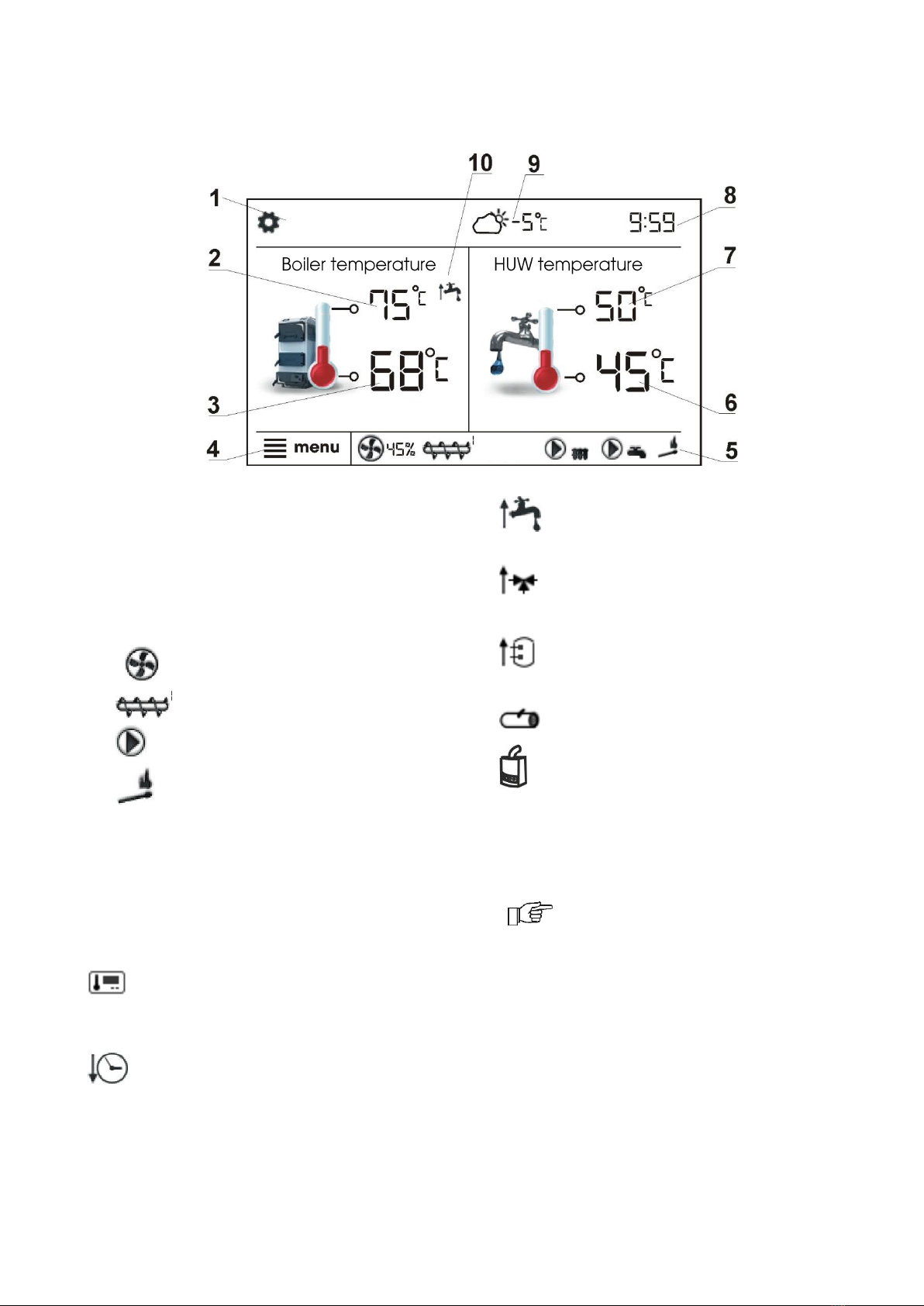
8.1 Description of display main window
1. mode of regulator operation: FIRING UP,
OPERATION, SUPERVISION BURNING
OFF, STANDSTILL
2. preset boiler temperature
3. measured boiler temperature
4. key to enter ’’Menu” list
5. Information field:
fan
feeder
pumps
igniter
6. measured temperature of HUW container
7. preset temperature of HUW container
8. clock time and weekday
9. outside temperature (weather)
10. field of functions, which modify preset
temperature -meaning of the symbols:
- opening of room thermostat contacts
–preset room temperature has been
reached,
- of preset boiler temperature for
active time intervals,
- increase of preset boiler temperature
for the time of HUW container filling,
- increase of preset boiler temperature
by mixer circuit,
- increase of preset temperature for
buffer loading,
- operation mode –grate,
- work on the reserve boiler (gas- or oil-
).
Both, left and right window may
display different information. By
touching the screen, user may
navigate between displayed
information: mixer circuits
information window, HUW window,
fuel level window.
Fuel level may be displayed on ecoSTER
TOUCH room control panel.
OPERATION
THU
10
8.2 Switching on/off the boiler
Make sure fuel is present in the tank and
tank hatch is closed. Now boiler may be
switched on. To start the boiler - press
BURNER OFF? at any place on the screen.
The message: „Active regulator?”appears.
Confirm the message. Boiler enters firing-up
stage.
There is also another method of boiler start-
up. Press MENU button and find and press
button in pie menu.
To stop the boiler - press MENU button, and
find and press button in pie menu.
8.3 Settings preset temperature
Preset boiler temperature or preset HUW
temperature, just like the preset mixer
circuit temperature, can be set in the menu:
Boiler settings →Preset boiler temp.
HUW settings →HUW preset temp.
Mixer 1-4 settings →Preset mixer temp.
The value set as Preset boiler temp. is
ignored by the regulator if the preset boiler
temperature is controlled by weather sensor.
Regardless of that, the preset boiler
temperature is automatically increased in
order to fill the hot utility water tank and
feed heating mixer cycles.
8.4 FIRING UP
The FIRING UP mode is used for automatic
firing up of furnace in the boiler.
All parameters which influence the firing-up
process can be found in menu:
Service settings →Burner settings →
Firing up
If firing up the furnace fails, further attempts
are carried. Consecutive attempts are
visualised by numbers next to the lighter
symbol .
After three unsuccessful attempts, an alarm
Failed firing up attempt is reported. In such
case, the boiler operation is halted. Boiler
operation cannot be continued automatically
- service crew must intervene. After
removing causes of impossibility to fire up,
the boiler must be restarted.
8.5 OPERATION
The fan operates continuously. Fuel feeder is
activated cyclically. A cycle consists of feeder
operation time and duration of feeding
interval
Parameters related with the Operation mode
are: Feeder operation time and Fan output
in:
Boiler settings →Output modulation
8.6 Regulation mode
There are two regulation modes for
stabilizing the set temperature of the boiler:
Standard and FuzzyLogic
Boiler settings →Regulation mode
Operating in Standard Mode
When the boiler temperature reaches its set
value, the regulator switches to
SUPERVISION mode.
The regulator has a boiler output modulation
mechanism allowing it to gradually reduce
the output as the boiler temperature nears
its set value
Three boiler output levels can be set:
maximum, medium, and minimum. Each
level can be additionally adjusted with
individual fuel feeding times and fan speeds,
affecting the actual output of the boiler. The
output level parameters are accessible
through the menu
Boiler Settings →Output modulation.
The regulator sets the current output of the
burner depending on the set temperature of
the boiler and H1 and H2 hysteresis settings
It is possible to set the H1 and H2 values to
modulate the output withouth the medium
power stage, ie. reducing output from 100%
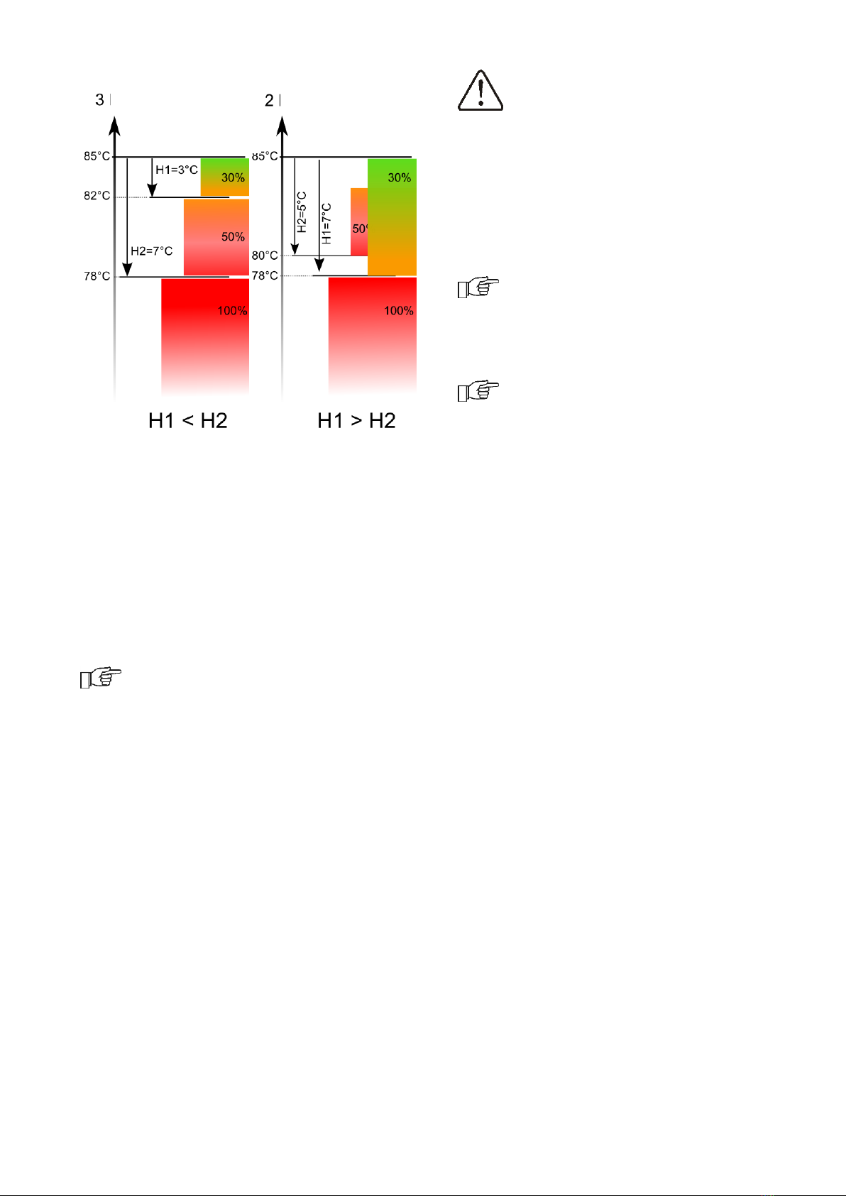
11
to 30%, skipping the 50% output (right side
of the figure below).
Operating in FuzzyLogic mode
In FuzzyLogic mode, the regulator
automatically sets the output of the burner in
order to maintain the set boiler temperature.
The regulator uses the output settings
predefined in Standard mode. This mode
does not require setting the H1 and H2
hysteresis.
Note: If only the HUW is heated
(summer mode), it is recommended
to set the regulator to Standard
mode.
After the set temperature is exceeded by
5ºC, the boiler switches to SUPERVISION
mode.
8.7 SUPERVISION
In SUPERVISION mode, the fan and the
feeder are switched on cyclicall at larger
intervals than in OPERATION mode. This is to
prevent the fire from being extinguished.
Supervision parameters can be found in
menu:
Service Settings →Burner Settings →
Supervision
SUPERVISION parameters should be set in
accordance with the recommendations of the
boiler or burner manufacturer. The
parameters should be adjusted to prevent
the furnace from extinguishing during
intervals.
Parameters should be so selected
that the boiler temperature in this
mode gradually drops. Incorrect
settings may lead to boiler
overheating.
When the supervision time expires, the
regulator switches to BURNING OFF mode,
unless the boiler temperature decreases and
the boiler automatically switches to
OPERATION mode.
For the setting Supervision time =
0, the regulator skips the
SUPERVISION mode and enters the
BURNING-OFF mode.
When the Supervision time = 255,
the regulator will work continuously
in SUPERVISION mode, until the
boiler temperature decreases and it
automatically switches to
OPERATION mode.
8.8 BURNING OFF
The extinguishing process does not occur
when coal is the fuel of choice. When pellets
are the fuel, they are burned off for several
minutes (depending on the set time). After
BURNING OFF, the regulator switches to
STANDSTILL.
8.9 STANDSTILL
In the STANDSTILL mode, the boiler is put
out and awaits signal to resume heating.
A signal to start heating can be:
decrease in preset boiler temperature
below the preset temperature minus the
value of boiler hysteresis Boiler hysteresis,
if the boiler is set to work with a buffer -
decrease in upper buffer temperature
below the preset value Buffer loading start
temperature.
8.10 Domestic hot water settings
HUW
The device controls temperature of the
domestic how water - HUW –tank, provided
that a HUW temperature sensor is
connected. If the sensor is disconnected, an
information about lack thereof is displayed in
the main window. The parameter:
Menu →HUW settings →HUW pump
mode allows the user to:
disable filling of the tank, parameter Off,
Power levels
Power levels
Preset
temperature T=85°C
Preset
temperature T=85°C

12
set HUW priority, using the Priority
parameter - in this case, the CH pump is
deactivated to speed up filling of the
HUW tank.
set simultaneous operation of the CH and
HUW pump, using parameter No priority.
8.11 Setting HUW preset
temperature
Preset HUW temperature is defined by
parameter:
HUW settings →HUW preset temp.
8.12 HUW container hysteresis
Below HUW preset temp. –HUW container
hysteresis starts HUW pump to load the HUW
container.
After setting a low hysteresis value,
HUW pump will run faster when
HUW temperature falls.
8.13 HUW circulation
The settings can be found in:
HUW Settings → Schedule - circulation
pumps
and
Service settings → CH and HUW settings
Setting of circulating pump control is
analogical to night decrease setting.
Circulating pump switches on in selected
time intervals. In disregarded time intervals
circulating pump will start and remain in
operation for the period of time set in
Circulating pump operation time , then will
stop and remain out of operation for the
period of time set in Circulating pump
standstill time.
8.14 Enabling the SUMMER function
In order to activate the SUMMER function,
which enables to load the HUW tank in the
summer, without the need for activating the
CH system and mixer cycles, set the
parameter SUMMER mode to Summer.
Summer/Winter →SUMMER mode
In Summer mode, all heat
receivers may be shut off, so
before enabling it please make
sure that the boiler does not
overheat.
If the weather sensor is connected SUMMER
function can be activated automatically with
the Auto parameter including settings for
SUMMER mode act. temperature, SUMMER
mode deact. temperature.
8.15 Disinfection HUW container
The regulator has a function of automatic,
periodic heating of HUW container to 70°C to
eliminate bacterial flora from the HUW
container.
Keep the tenants informed of
activating the disinfection function
as there is risk of being burnt with
hot usable water.
The regulator increases the HUW container
temperature once a week, at 2:00 a.m.
Monday. After 10 minutes of maintaining the
temperature at 70°C, the HUW pump is
switched off and the boiler returns to normal
operation. Do not activate the disinfection
function when the HUW support is off.
8.16 Mixer circuits settings
Settings for the first mixer circuit can be
found in the menu: Mixer 1 settings
Settings for other mixers can be accessed in
next menu items and they are identical for
each circuit.
Settings for mixer without weather
sensor
It is necessary to manually set the required
water temperature in the heating mixer
circuit using parameter Preset mixer temp.,
e.g. at a value of 50°C. The value should
allow to obtain the required room
temperature.
After connecting room thermostat, it is
necessary to set a value of decrease in
preset mixer temperature by thermostat
(parameters Mixer room therm.) e.g. at 5°C.
This value should be selected by trial and
error. The room thermostat can be a
traditional thermostat (NO-NC), or room
panel ecoSTER TOUCH. Upon activation of
the thermostat, the preset mixer circuit
temperature will be decreased, which, if
proper decrease value is selected, will stop
growth of temperature in the heated room.

13
Settings for mixer with weather sensor
without room thermostat ecoSTER
TOUCH
Set parameter Mixer weather control to On.
Select weather curve. Using parameter
Curve translation, set preset room
temperature following the formula:
Preset room temperature = 20°C + heating
curve translation.
In this setup, it is possible to connect a room
thermostat which will equalize the inaccuracy
of selecting heating curve, if the selected
heating curve value is too high. In such case,
it is necessary to set the value of preset
mixer temperature decrease by thermostat,
e.g. at 2°C. After opening of the thermostat
contacts, the preset mixer circuit
temperature will be decreased, which, if
proper decrease value is selected, will stop
growth of temperature in the heated room.
Settings for mixer with weather sensor
and with room thermostat
Set parameter Mixer weather control to On.
Select weather curve. The room panel
automatically translates the heating curve,
depending on the preset room temperature.
The regulator relates the setting to 20°C,
e.g. for preset room temperature = 22°C,
the regulator will translate the heating curve
by 2°C, for preset room temperature = 18°C,
the regulator will translate the heating curve
by -2°C. In some cases it may be necessary
to fine-tune the heating curve translation.
In this setup, the ecoSTER TOUCH room
thermostat can:
- decrease the heating cycle temperature by
a constant value when the preset room
temperature is reached. Analogously, as
specified in the previous point (not
recommended), or
- automatically, continuously correct the
heating cycle temperature.
It is not recommended to use both options at
the same time.
Automatic correction of room temperature is
carried out in accordance with the following
formula:
Correction = (Preset room temperature -
measured room temperature) x room
temperature coefficient /10
Example:
Preset temperature in the heated room (set
at ecoSTER TOUCH) = 22°C. Temperature
measured in the room (by ecoSTER TOUCH)
= 20°C. Room temp. factor. = 15.
Preset mixer temperature will be increased
by (22°C - 20°C) x 15/10 = 3°C.
It is necessary to find appropriate value of
the Room temp. factor. The higher the
coefficient, the greater the correction of
preset boiler temperature. If the setting is
“0”, the preset mixer temperature is not
corrected. Note: setting a value of the room
temperature coefficient too high may cause
cyclical fluctuations of the room temperature!
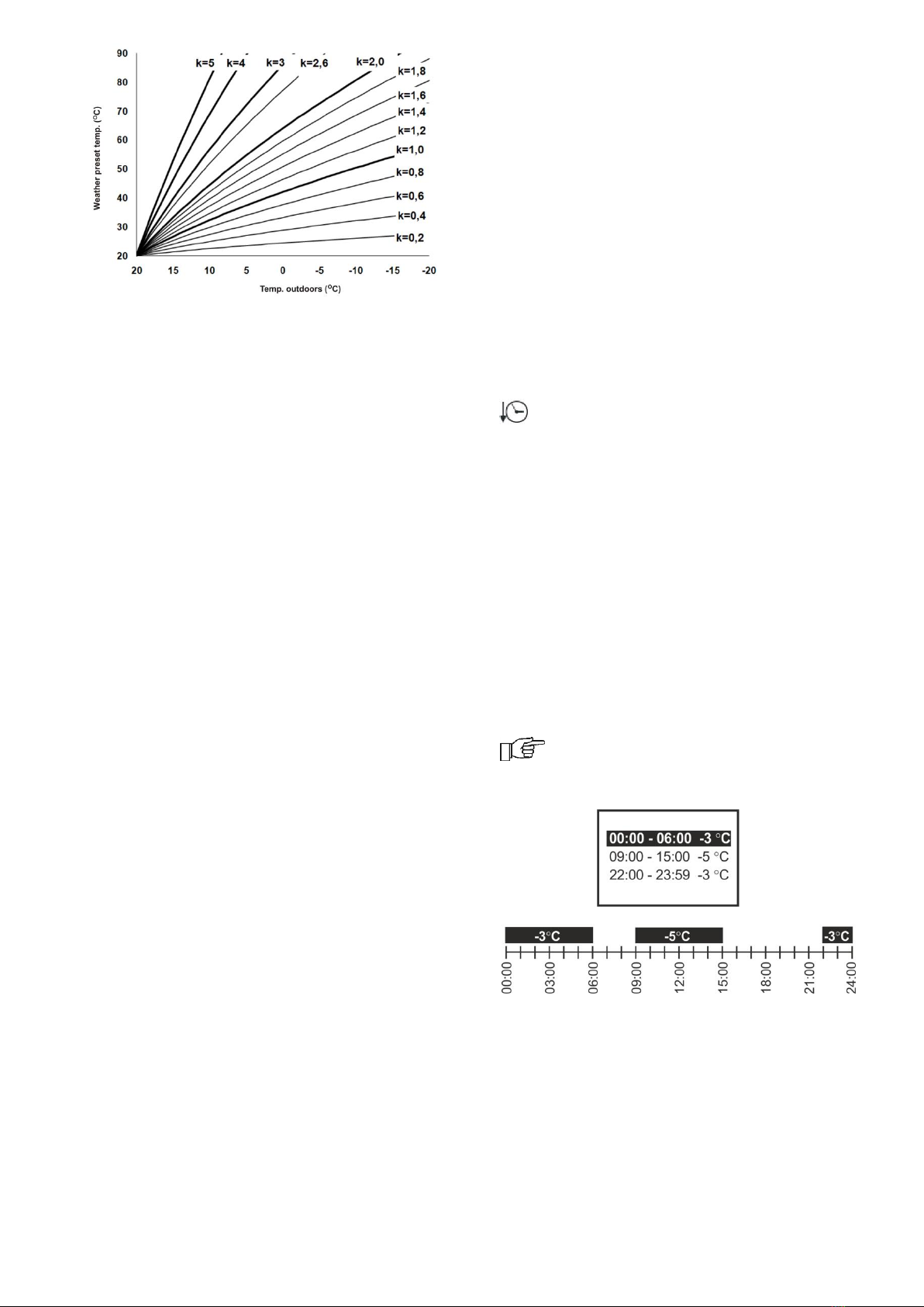
8.17 Weather controlled
Depending on the temperature measured
outside the building, both preset boiler
temperature and temperatures of mixer
circuits can be controlled automatically. If
proper heating curve is selected, the
temperature of the circuits is calculated
automatically, depending on the outdoor
temperature. Thus, if the selected heating
curve is appropriate for the given building,
the room temperature stays more or less the
same, regardless of the temperature outside.
Note: during trial and error selection of
appropriate heating curve, it is necessary to
exclude influence of the room thermostat on
regulator operation (regardless of whether
the room thermostat is connected or not), by
setting the parameter:
Mixer 1 settings →Mixer room therm. =
0.
If a room panel ecoSTER TOUCH is
connected, it is also necessary to set the
parameter Room temperature factor = 0.
Guidelines for proper setting of the heating
curve:
floor heating 0,2 -0,6
radiator heating 1,0 - 1,6
boiler 1,8 - 4
14
Guidelines for selection of appropriate
heating curve:
- if the outdoor temperature drops, and the
room temperature increases, the selected
heating curve value is too high,
- if the outdoor temperature drops, and the
room temperature drops as well, the selected
heating curve value is too low,
- if during frosty weather the room
temperature is proper, but when it gets
warmer - it is too low, it is recommended to
increase the Curve translation and to select a
lower heating curve,
- if during frosty weather the room
temperature is too low, and when it gets
warmer - it is too high, it is recommended to
decrease the Curve translation and to select
a higher heating curve.
Buildings with poor thermal insulation require
higher heating curves, whereas for buildings
which have good thermal insulation, the
heating curve can have lower value.
The regulator can increase or decrease the
preset temperature, calculated in accordance
with the heating curve, if it exceeds the
temperature range for the given circuit.
8.18 Description of night time decrease
settings
Night time decreases for boiler, heating
circuits, HUW container and circulation
pump operation.
The intervals can be used to define time
periods at which lower preset temperature
may be set e.g. for a night time or when the
user is not at home. This feature enables
automatic reduction of preset temperature
without compromising the heat comfort and
reduces fuel consumption.
Decrease of preset temperature in selected
time intervals is indicated by the symbol:
on the main screen.
To activate time intervals, set the parameter
Schedule for boiler or for the given heating
circuit to ON.
The parameter Reduction value set the
temperature reduction, one for all time
intervals.
Night time decreases can be defined
separately for every day of the week set
Schedule.
The example of night time decrease of preset
temperature from 22:00 to 06:00 next day
and from 09:00 to 15:00 is given below.
Note! Setting of time intervals for
24 hours (one day) should start
from 00:00!
In the given example, the regulator will set
the decrease of preset temperature by 3°C
from 00:00 to 06:00, and will keep the
preset value (without the decrease) from
06:00 to 09:00. Then, it will set the decrease
by 5°C from 09:00 to 15:00, and will keep
the preset value (without the decrease)
again from 15:00 to 22:00; and again will

15
set the decrease by 3°C from 22:00 to
23:59.
Time interval is disregarded when
its decrease is set to "0" even
though "from... to ..." values have
been entered.
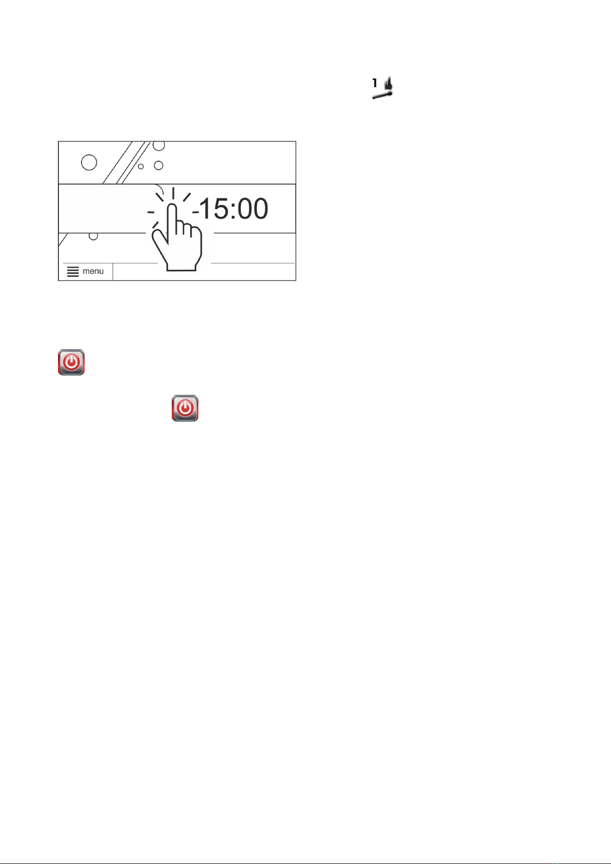
8.19 Fuel level setup
Activating the fuel level gauge
In order to enable display of the fuel level,
set value of parameter
Boiler settings →Fuel level →Alarm level
to a value greater than zero, e.g. 10%. By
pressing the right or left box in the main
window you can select the fuel level
indicator. Fuel level can also be displayed on
the ecoSTER TOUCH room panel.
Operation of fuel level indicator
Any time upon filling fuel tank, press and
hold pressed current fuel level value.
Following prompt appears:
"Set fuel level at 100% Once selected and
confirmed YES, fuel level is set at 100%.
Once selected and confirmed YES, fuel level
is set to 100%.
Note: Fuel may be replenished at any time
without a need to wait for complete empty
fuel tank. Replenish fuel always to the level
corresponding to 100% level of the fuel tank
and set 100% level as described above.
Description of operation
The regulator calculates the fuel level basing
on the current fuel consumption. Default
settings do not always correspond to the
actual consumption of fuel by the given
boiler, therefore, for proper operation this
method requires the regulator user to
perform level calibration. No additional fuel
level sensors are required.
Calibration
To perform calibration - fill the fuel tank to
the level corresponding to its full load and
set the parameter:
Boiler settings →Fuel Level → Fuel level
calibration →Fuel Level 100%
The indicator in the main window will be set
to 100%. On-going calibration process is
signalled by flashing fuel level gauge. The
gauge will flash until the time of marking the
point corresponding to minimal fuel level.
One must systematically control the
decreasing level of fuel in the bin. When the
level reaches the requested minimum, set
the value of the parameter:
Boiler settings →Fuel Level → Fuel level
calibration →Fuel Level 0%
Calibration can be skipped if the Feeder
Efficiency and Tank capacity, parameters are
set correctly in: Menu →Service settings
→Burner settings → Operation
8.20 Information
Information" menu allows to preview
temperatures being measured and to
recognize which equipment is currently ON.
Upon connection of mixers'
extension module, information
windows of additional mixers are
displayed.
8.21 Manual control
Regulator offers possibility to manual start of
working equipment such as pump, feeder
motor or fan. This feature enables checking
whether the given equipment is fault-free
and properly connected
Note: Access to manual control
menu is possible only in the STAND-
BY mode, i.e. when the boiler is
OFF.
Note: Long-term operation of the
fan, the feeder or other working
equipment may lead to occurrence
of hazardous conditions.
8.22 Grate

16
The regulator is able to work with a Grate,
where the fuel is loaded manually. The
feeder is switched off, but the fan is
operational. You can switch between Burner
and Grate modes in:
Boiler settings → Heat source
Fan speeds are regulated in:
Boiler settings →Output modulation
Fan speed settings are different for the grate
than for the burner. Other parameters are
set in the service settings.
Changing modes between grate and
burner can be done via the ecoNET
internet module, but only after all
the manually loaded fuel is burned
off. In order to change modes, turn
the regulator off and on by clicking
“Work mode” in the “Current
information” tab.
8.23 Favourite menu
In Touch version in the menu bar at the
bottom of the screen there is a button:
. Upon activation of this key, a
quick selection menu appears. To add new
item to this menu - hold respective icon
pressed in pie menu for a while.
To remove selected item from favourite
menu - hold corresponding icon pressed and
confirm REMOVE.
8.24 Room panel ecoSTER TOUCH
The controller can work together with
ecoSTER TOUCH remote control device,
which have a built-in room thermostat. This
room panel shows useful information such
as: fuel level, alarm indication etc.
8.25 Internet module
The controller can work together with
ecoNET300 internet module. It enables
online control and supervision over the
controller for the help of the website
www.econet24.com. You can use the
convenient mobile application ecoNET.apk.
Mobile application can be downloaded free of
charge from the website:

INSTALLATION AND SERVICE SETTINGS
ecoMAX 860P TOUCH

18
9Hydraulic diagrams
The presented hydraulic diagram does not replace central heating engineering
design and may be used for information purposes only.
Diagram with 4-way control valve for central heating circuit: 1 –boiler, 2 –controller, 3 - water
temperature sensor returning to the boiler, 4 –boiler temperature sensor, 5 –exhaust temperature sensor
(temperature monitoring only), 6 –4-way valve servo, 7 –mixer circuit pump, 8 –mixer circuit temperature
sensor, 9 –HUW container, 10 –HUW pump, 11 –HUW sensor, 12 –weather temp. sensor, 13 –ecoSTER
TOUCH room control panel or standard room thermostat, 14 –thermal isolation.
In order for the valve (6) to be able to effectively increase the return water temperature,
set a high set temperature of the boiler. In order to improve the water circulation in
natural systems (highlighted circuit in the figure): use large nominal diameter pipes and
four-way valve, avoid unnecessary angles and reductions, maintain a min. 2° horizontal
pipe slope, etc. If the sensor (3) is attached to the pipe, isolate it with foam surrounding
the pipe and sensor.
RECOMMENDED SETTINGS:
Parameter
Setting
MENU
Preset boiler temperature
75-80C
menuBoiler settings
Min. preset boiler temperature
65C
menuService settingsBoiler settings
Increasing of preset boiler temp.
5-20C
menuService settingsCH and HUW settings
Mixer 1 support
CH ON
menuService settingsMixer 1 settings
Maxer 1 preset temperature
70C
menuService settingsMixer 1 settings
Mixer 1 heating curve
0.8 –1.4
menuMixer 1 settings
Mixer 1 weather control
ON
menuMixer 1 settings
Mixer 1 thermostat selection
ecoSTER T1
menuService settingsMixer 1 settings

19
Diagram with two adjustable heating circuits and the HUW container:1 –boiler, 2 –heat exchanger,
3 –controller, 4 –boiler temperature sensor, 5 –exhaust temperature sensor (temperature monitoring
only), 6 –boiler pump, 8 –HUW pump, 9 –HUW container, 10 –HUW temperature sensor, 11 –mixer
pump, 12 –ecoSTER TOUCH room control panel with room thermostat feature , 13 –HUW container
temperature sensor CT4, 14 - weather temp. sensor, 15 - safety thermostat off the underfloor heating
pump, 16 - expansion tank.
RECOMMENDED SETTINGS:
Parameter
Setting
MENU
CH pump activation temperature
55C
menuService settingsCH and HUW settings
CH pump = boiler pump
YES
menuService settingsCH and HUW settings
Mixer 1 support
CH activated
menuService settingsMixer 1 control
Max. preset temp. of mixer 1
70C
menuService settingsMixer 1 settings
Mixer 1 heating curve
0.8 –1.4
menuMixer 1 settings
Mixer 1 weather control
activated
menuMixer 1 settings
Mixer 1 thermostat selection*
ecoSTER T1
menuService settingsMixer 1 settings
Mixer 2 support
Activate floor
menuService settingsMixer 2 settings
Max. preset temp. of mixer 2
45C
menuService settingsMixer 2 settings
Mixer 2 heating curve
0.3 –0.8
menuMixer 2 settings
Mixer 2 weather control
activated
menuMixer 2 settings
Mixer 2 thermostat selection*
ecoSTER T1
menuService settingsMixer 2 settings
20
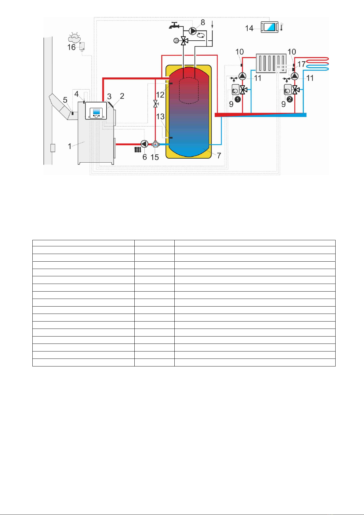
Diagram with heat buffer, where: 1 –boiler, 2 –burner, 3 –controller, 4 –boiler temperature sensor, 5
–exhaust temperature sensor, 6 –boiler pump, 7 –heat buffer, 8 –HUW pump , 9 - mixing valve actuator,
10 - mixer temperature sensor, 11 - mixer pump, 12 - upper sensor of buffer temperature, 13 - lower
sensor of buffer temperature, 14 - ecoSTER TOUCH room control panel, 15 - thermostatic three-way valve
to the return protection, 16 –weather temp. sensor, 17 - thermostat to turn off the pump.
RECOMMENDED SETTINGS:
Parameter
Setting
MENU
Boiler preset temperature
80C
menuBoiler settings
Min. boiler preset temperature
75C
menuService settingsBoiler settings
CH pump activation temperature
55C
menuService settingsCH and HUW settings
Buffer support
activated
menuService settingsBuffer settings
Loading start temperature
50C
menuService settingsBuffer settings
Loading stop temperature
75C
menuService settingsBuffer settings
Mixer 1 support
CH activated
menuService settingsMixer 1 settings
Max. preset temp. of mixer 1
70C
menuService settingsMixer 1 settings
Mixer 1 heating curve
0.8 –1.4
menuMixer 1 settings
Mixer 1 weather control
activated
menuMixer 1 settings
Mixer 1 thermostat selection*
ecoSTER T1
menuService settingsMixer 1 settings
Mixer 2 support
Activate floor
menuService settingsMixer 2 settings
Max. preset temp. of mixer 2
45C
menuService settingsMixer 2 settings
Mixer 2 heating curve
0.3 –0.8
menuMixer 2 settings
Mixer 2 weather control
activated
menuMixer 2 settings
Mixer 2 thermostat selection*
ecoSTER T1
menuService settingsMixer 2 settings
* When using a standard room thermostate with ON/OFF terminals instead of the ecoSTER TOUCH (14),
select the Universal option, or when the setting is hidden, do not choose anything.
Table of contents
Other Metal-Fach Controllers manuals


Popular Controllers manuals by other brands

Nice
Nice One-Max Installation and use instructions and warnings

Meaco
Meaco LAE quick start guide

Viconics
Viconics VT7600W Series installation guide

G-Scale Graphics
G-Scale Graphics LSCM2 Operation and installation manual

Siemens
Siemens Sirius 3RW44 V.6.2 Getting started

BleBox
BleBox shutterbox user manual

Advanced Control Technologies
Advanced Control Technologies th104 installation instructions

Unitronics
Unitronics Vision V350-35-TU24 installation guide

WEG
WEG SSW900 Series user guide

Samson
Samson TROVIS 5433 quick guide

T-solution
T-solution SV-iG5 user manual

Armacost Lighting
Armacost Lighting ProLine 713429 instructions


