MetalMaster HG-2506 User manual

SWINGBEAM GUILLOTINE
OPERATION MANUAL
Edition No : SB001
Date of Issue : 5/07/2016
Models.
HG-2504, HG-2506, HG-3206
HG-3212, HG-4006, HG-4012
Page 1
Instructions Manual for HG-4012 (S948)
12/02/2018

2
OPERATION MANUAL
NOTE:
In order to see the type and model of the machine, please see the
specication plate. Usually found on the back of the machine. See
example (Fig.1)
Fig.1
HYDRAULIC GUILLOTINE
MACHINE
MODEL NO.
SERIAL NO.
DATE OF MANF.
Note:
is manual is only for your reference. Owing to the continuous improvement of the
machine, changes may be made at any time without obligation or notice. Please ensure
the local voltage is the same as listed on the specication plate before operating this
electric machine.
Distributed by
www.machineryhouse.co.nz
MACHINE DETAILS
Page 2
Instructions Manual for HG-4012 (S948)
12/02/2018

3
OPERATION MANUAL
C O N T E N T S:
1. GENERAL MACHINE INFORMATION
1.1 Specications.................................................................4
1.2 Standard Equipment.....................................................4
1.3 Overall Drawings..........................................................5
2. IMPORTANT INFORMATION
2.1 Safety Requirements......................................................6
2.2 Safety Features of the Machine................................... 8
2.3 Liing Instructions......................................................10
3. INSTALLATION
3.1 Base Foundation and Securing Points..................... 11
3.2 Machine Leveling.........................................................12
3.3 Checking the Power Supply........................................12
3.4 Attaching the Accessories...........................................13
3.5 Fill the Hydraulic Oil Tank........................................14
4. COMMISSIONING
4.1 Preparation of the Machine.......................................15
4.2 Omrom E3Z Safety Sensor Alignment....................16
4.3 Calibrate “X” Axis on Controller..............................18
4.4 Commissioning Check List.......................................18
5. OPERATION INSTRUCTION
5.1 Pre-Operational Safety Check Prior to Operating. 19
5.2 NC89 Controller Operation.......................................20
5.3 Setting the Blade Gap..................................................21
6. MAINTENANCE
6.1 Type and frequency of Inspections...........................22
6.2 Lubrication Points.......................................................23
6.3 Changing Oil...............................................................24
6.4 Changing e Filter....................................................25
6.5 Adjusting Blade Clearance & Parallelism.................26
6.6 Troubleshooting..........................................................27
APPENDIX
A. Hydraulic Circuit Diagram..........................................28
B. Electrical Circuit Diagram...........................................30
General Machinery Safety Instructions..........................34
Page 3
Instructions Manual for HG-4012 (S948)
12/02/2018

4
OPERATION MANUAL
Machine Type HG-2504 HG-2506 HG-3206 HG-3212 HG-4006 HG-4012
Shearing Length (mm) 2500 2500 3200 3200 4000 4000
Material Capacity Mild Steel (mm) 4 6 6 12 6 12
Material Capacity Stainless Steel (mm) 2.5 4 4 8 4 8
Shear Angle (degree) 1.5 1.5 1.5 1.5 1.5 1.5
Back Gauge Range (mm) 900 1000 1000 1000 1000 1000
System Pressure 18 18 18 18 18 18
Oil Tank Volume 150 170 205 300 205 420
Dimensions Width (mm)
Depth (mm)
Height (mm)
3130
1530
1600
3130
1530
1600
3840
1675
1620
3925
1800
1940
4630
1800
1700
4735
2000
2040
Height of Work Table (mm) 740 800 800 800 800 860
Weight (kgs) 4000 5280 7100 11000 8860 13500
Main Motor 3 Phase 415 V 50Hz (kW) 4 7.5 7.5 18.5 7.5 18.5
Back Gauge 3 Phase 415 V 50 Hz (kW) 0.55 0.55 0.55 0.55 0.55 0.55
1.1 SPECIFICATIONS:
1.2. STANDARD EQUIPMENT:
Back-gauge assembly
Front guarding
Foot switch and control panel
Front sheet supports
Toolset and Instruction manual
OPTIONAL EQUIPMENT
Rear pneumatic sheet supports.
Page 4
Instructions Manual for HG-4012 (S948)
12/02/2018

5
OPERATION MANUAL
D
A
B
C
mm HG-2504 HG-2506 HG-3206 HG-3212 HG-4005 HG-4012
A 3130 3130 3840 3925 4630 4735
B 3230 3230 3990 4175 4830 4935
C 1600 1600 1620 1940 1700 2040
D 1530 1530 1675 1800 1800 2000
1.3. OVERALL DRAWINGS
Page 5
Instructions Manual for HG-4012 (S948)
12/02/2018
6
OPERATION MANUAL
e most common metal guillotine injuries are crushed or amputated ngers.
Most of these accidents are not caused by the blade of the guillotine, but by the clamps that hold
the sheet metal being cut. Other injuries are from ngers jamming under the sheet that is to be
cut, and strain injuries while handling large and awkward sheets of metal.
By law, guillotines must be guarded, and operators must be trained. Safe working procedures must
be in place to prevent injuries.
2.1 SAFETY REQUIREMENTS
DO NOT use this machine unless a qualied person has instructed you in the safe use and opera-
tion of the machine.
e following guidelines can be used to identify workplace hazards and to reduce the risks when
using metal guillotines.
It is an unsafe practice for two people to work at a guillotine unless both operators are provided
with interlocked actuating devices (usually a foot control). However in some guillotine operations,
for example cutting large sheets, two operators may be required to maneuver the sheets into position
before cutting. For such operations safe work procedures should be developed to control any
hazards.
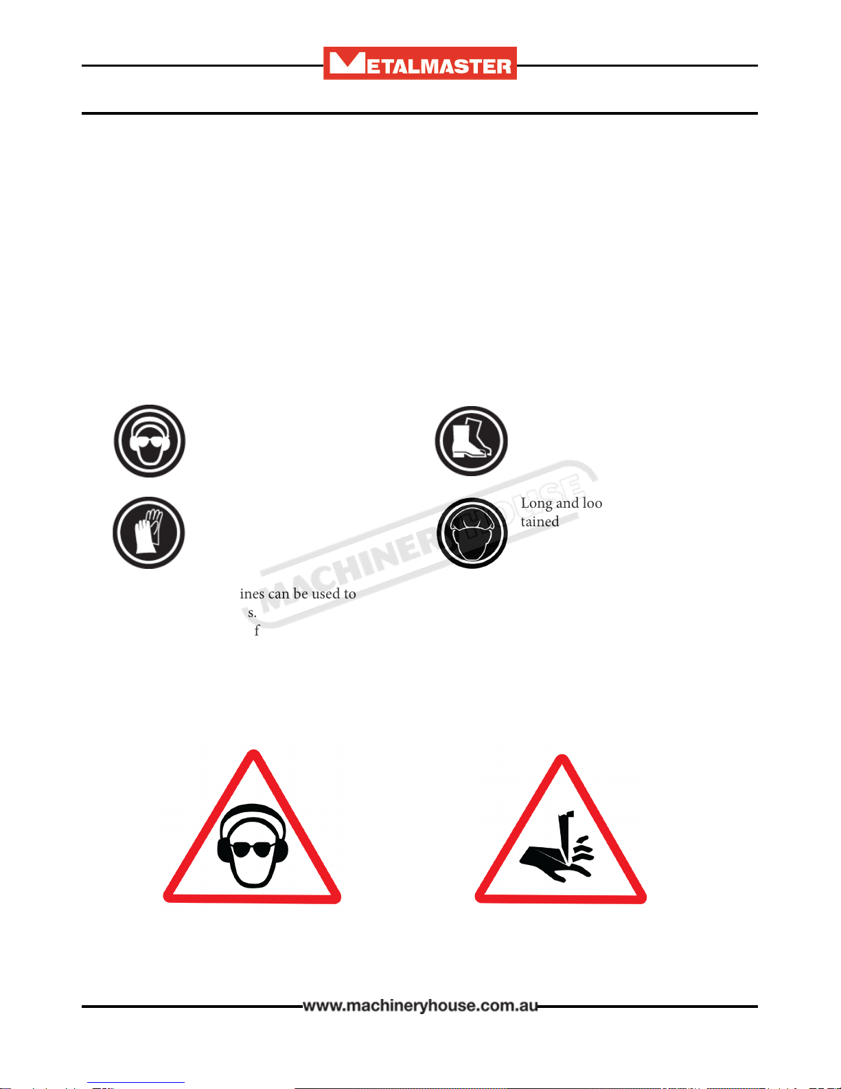
Safety glasses must be worn at
all times in work areas. Earmus
should be worn if the work area is
noisy.
Sturdy footwear must be worn at
all times in work areas.
Gloves should be worn when han-
dling the material used on this
machine.
Long and loose hair must be con-
tained with a net or under a hat
Page 6
Instructions Manual for HG-4012 (S948)
12/02/2018

7
OPERATION MANUAL
SAFETY CHECKS BEFORE OPERATING
qEnsure xed guards are in place to prevent hands or other parts of the body from entering
area’s of high risk
qGuards or safety devices must never be removed or adjusted, except by an authorized person
for maintenance purposes.
qWorking parts should be well lubricated and free of rust and dirt.
qe area around the machine must be adequately lit and kept free of materials, which might
cause slips or trips.
qBe aware of other personnel in the immediate vicinity and ensure the area is clear before using
equipment.
qFamiliarize yourself with and check all machine operations and controls.
qEnsure cutting table is clear of scrap and tools.
qFaulty equipment must not be used. Immediately report suspect machinery
SAFETY CHECKS WHEN OPERATING
qDo not attempt to cut material beyond the capacity of the machine.
qNever attempt to cut rod, strap or wire with this machine.
qUse correct liing procedures when handling large sheets of material.
qTake extreme care during the initial feeding of the workpiece into the machine.
qe workpiece should always be held suciently far back from the edge being fed into the
guillotine.
qEnsure ngers and limbs are clear before operating the guillotine.
qHold material rmly to prevent inaccurate cutting due to creep.
qWhen cutting ensure feet are positioned to avoid contact with the foot operated lever.
SAFETY CHECKS AFTER OPERATION
qRemove all o cuts and place them in either the storage rack or waste bin.
qLeave the work area in a safe, clean and tidy state.
POTENTIAL HAZARDS
qCuts from the sharp edges and burrs on the sheets before and aer cutting
qParts of the body being caught in crush and pinch points.
qInjuries caused when handling metal sheets
Page 7
Instructions Manual for HG-4012 (S948)
12/02/2018

8
OPERATION MANUAL
e electrical and hydraulic circuits of your machine are designed to allow operation with maxi-
mum safety. e following precautions are available on the machine for enhanced safety.
ere are four Emergency stop buttons (engaging type) on the machine. Two are found on the
front of the machine, one on the foot switch control unit, and one on the main control unit. Once
the button has been pressed to reset the emergency stop, the red button must be rotated to reset
the stop.
2.2. SAFETY FEATURES OF THE MACHINE:
Foot pedal control
Emergency stop button (engaging type) is available on the foot switch control unit.
e foot pedal when pressed activates the shearing beam and must be held in the
depressed position until the machine has completed its cut.
Releasing the foot pedal during the shearing operation will return the machine to
the top of its stroke when controller is set to single cut.
Main Controls
e main machine operating controls are located on the pendant.
12 3 4
8
5 6 7
1 Continuous or Single Cut 5 Power On Indicator Light
2 Rear Guard Sensor Light 6 Illumimated Pump Start Button
3 Shadow Line Light ON/OFF 7 Hydraulic Pump Stop
4 Power ON/OFF to Controller 8 Emergency Stop
Page 8
Instructions Manual for HG-4012 (S948)
12/02/2018
9
OPERATION MANUAL
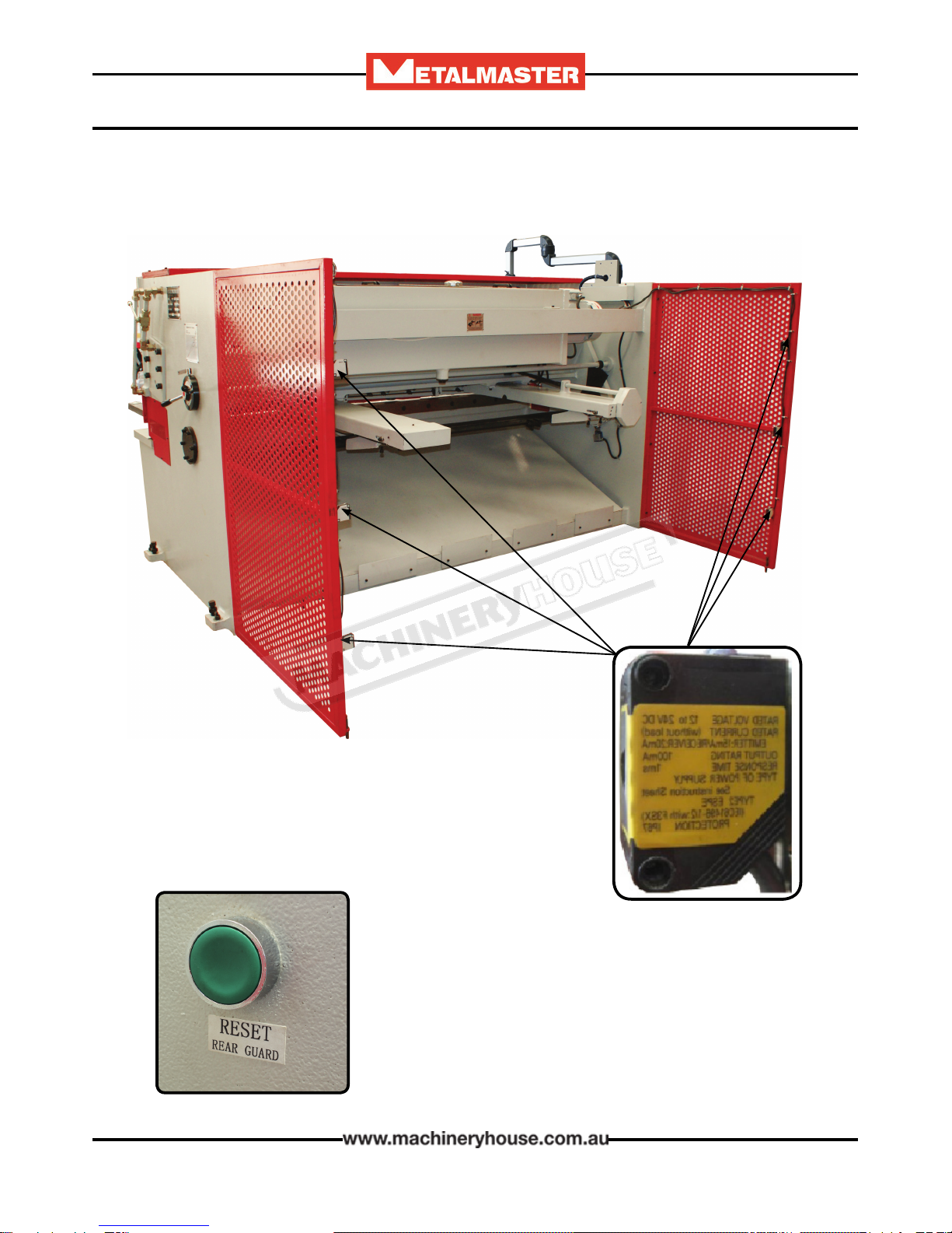
To prevent the operator or other persons from accidental injury the machine operation includes
a photoelectric light guard at the back of the machine
3 x Photoelectric safety cells are placed
on both sides of the back of the machine.
When the beam is broken the machine
stops.
Once the beam has been broken the system needs to be
reset. is is done by pressing the reset button on the
electrical cabinet.
Page 9
Instructions Manual for HG-4012 (S948)
12/02/2018

10
OPERATION MANUAL
2.3 LIFTING INSTRUCTIONS
On the day that the machine arrives, make sure that a crane with sucient capacity is available to
unload the machine from the vehicle. Make sure access to the chosen site is clear and that doors and
ceilings are suciently high and wide enough to receive the machine.
To handle the Guillotine, use only the two sling liing points located on the top of the end plates.
(Fig. 2.3) e slings should be positioned so the machine is level when lied.
When using slings please take note of the sling angle and the loads that apply
When the slings are at a 45° angle then each sling will carry
the equivalent of 50% of load weight. (Fig.2.1).
When the slings are at a 90° angle then each sling will carry
the equivalent of 75% of the load weight on each sling.
(Fig 2.2)
Note! Metalmaster recommend not to exceed 90° angle
Fig 2.2
Fig 2.1.
When liing the machine only use the liing points on the machine.
(Fig. 2.3) and sling as per diagram below. (Fig. 2.4) Ensure that when
liing, the machine does not tip over.
Check that the liing slings do not interfere with the hydraulic pipes or
electrical conduits. Certied liing slings only should be used.
Failure to follow these instructions could cause damage to the machine
Liing Points
Fig. 2.3
Liing Point
Fig. 2.4
Page 10
Instructions Manual for HG-4012 (S948)
12/02/2018

11
OPERATION MANUAL
e machine must be leveled and rmly stationed on the oor where it is to be used, according to
the Installation Diagram attached.
e oor load, must be suitable for the weight of the machine.
3. INSTALLATION
Before securing the machine a solid concrete base must be prepared to the specication of the
machine.
e sizes for the bolt holes position are listed as A-B listed in the chart below. Check the sizes with
the distributer
Model A B C D E F G
HG-2504 3500 2840 1000 1750 300 130 100
HG-2506 3500 2880 1150 1900 300 130 100
HG-3206 4200 3583 1350 1900 300 130 100
HG-3212 4700 3655 1450 2350 430 180 350
HG-4005 5000 4382 1500 1900 300 130 100
HG-4012 5500 4445 1550 2550 480 160 350
Table of Measurement
3.1 BASE FOUNDATION AND SECURING POINTS
Page 11
Instructions Manual for HG-4012 (S948)
12/02/2018
12
OPERATION MANUAL
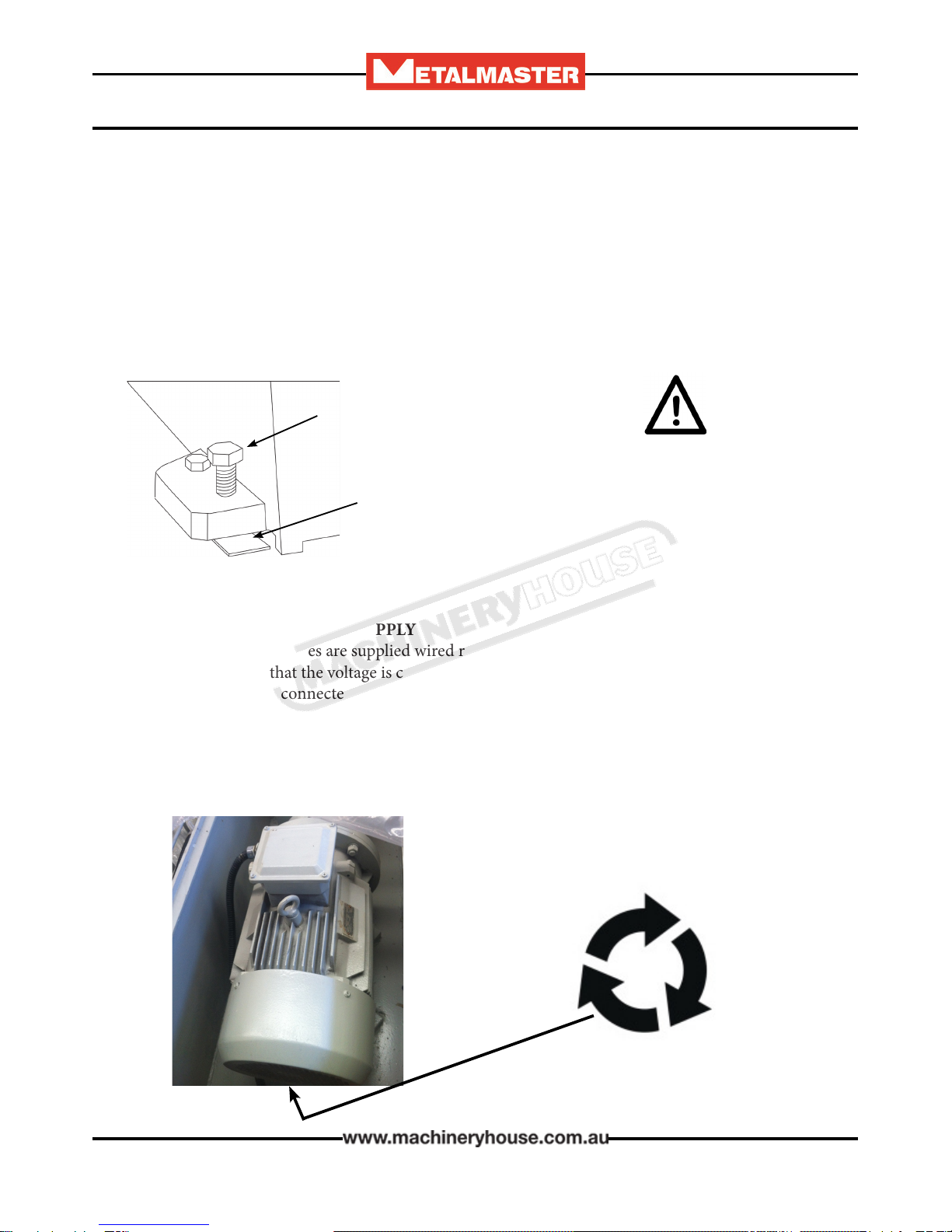
3.3 CHECKING THE POWER SUPPLY
METALMASTER machines are supplied wired ready to run. Check the specication plate on the
machine to conrm that the voltage is compatible with the local power supply.
e machine must be connected to the power by a qualied and licensed electrician. Warranty
may be voided if it is found that the connection was not carried out by a qualied electrician.
3.2 MACHINE LEVELING
To set your machine up so that it operates to optimum performance, apply the following procedure
Aer your guillotine has been anchored to a concrete slab oor, it then needs to be leveled. e
leveling is performed using the screws on each pad.(Fig. 3.1). Loosen the hold down bolts and
place a level on the surface of the working table. Tolerances: 1000:0.30mm, for both longitudinal
and transverse.
Metal plates need to be placed under each jacking screw to distribute the load. Once level then
tighten the hold down bolts.
Metal Plate
Jacking Screw
e machine must not rest on supports other
than those dened in Fig. 3.1
Fig. 3.1
Check the rotation of the motor. If the direction does not match the diagram below, isolate the
machine and change the wiring
Page 12
Instructions Manual for HG-4012 (S948)
12/02/2018
13
OPERATION MANUAL
Fig. 3.2
q Place the squaring stops Fig 3.3 into position on the table top,
securing into place with the bolts supplied. Check that the square
stops are square to the blade. Adjust by loosening the bolts and
moving by the amount allowed by the clearance of the holes.
q Re tighten the screws.
Fig. 3.3
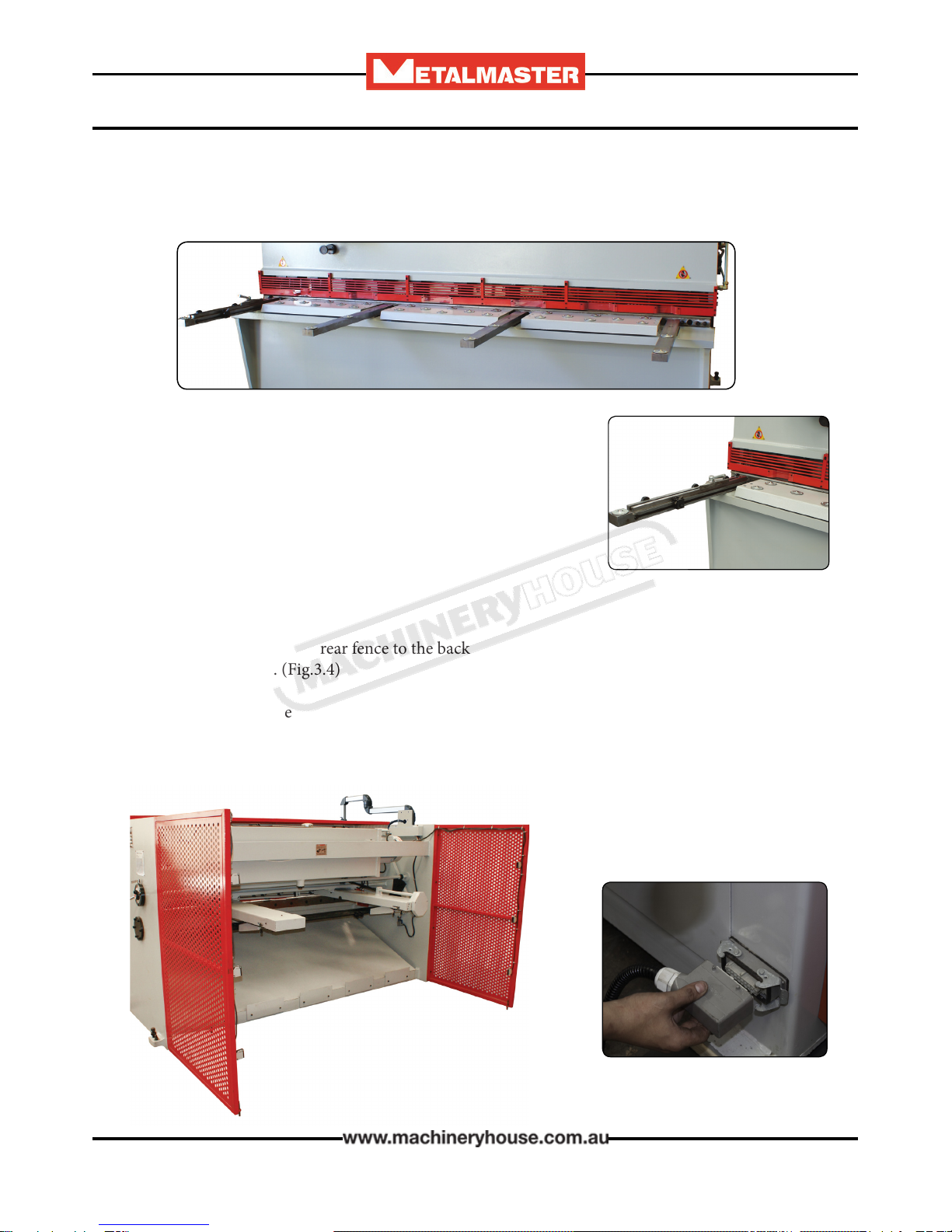
3.4 ATTACHING THE ACCESSORIES.
q Bolt the support arms onto the feed table. Ensure they are level and square to the table. (Fig 3.2)
q Unpack and attach the rear fence to the back of the machine. Ensure that the sensors have been
connected and set up. (Fig.3.4)
q Unpack the mobile foot control and plug the into the socket provided on the machine. (Fig.3.5)
Fig. 3.4
Fig. 3.5
Page 13
Instructions Manual for HG-4012 (S948)
12/02/2018
14
OPERATION MANUAL
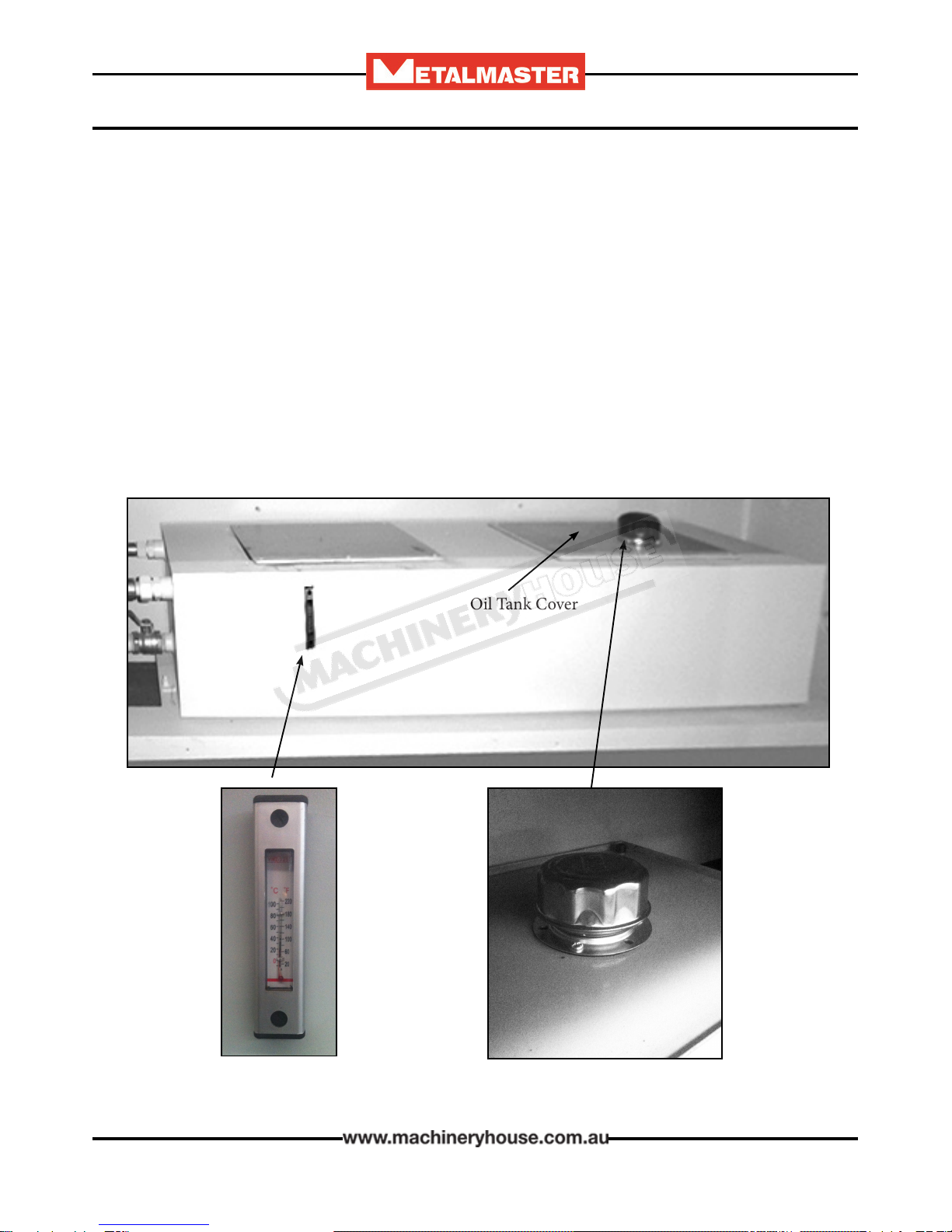
3.5 FILL THE HYDRAULIC OIL TANK.
When lling the tank with oil, make sure that the top of the tank is clean and free from dust and dirt.
q Remove the oil tank cover (Fig 5.5)
q Using a pump add the oil into the tank
q Oil level must be lled until the oil reaches the top mark of the oil indicator.
q Always keep the oil at the same level.
Fig. 5.5
Filler Cap
Sight Glass
Oil Tank Cover
Page 14
Instructions Manual for HG-4012 (S948)
12/02/2018

15
OPERATION MANUAL
4. COMMISSIONING
4.1. PREPARATION OF THE MACHINE.
q Remove all wrapping and packing grease from the machine.
q Check the machine for loose bolts. Tighten as required.
q Inspect for oil leakage or loose ttings. Similarly check the main rams between the top frames.
q Clean the blades and tighten the securing bolts as required. Examine the cutting edges of both
blades for damage.
q Inform your service provider of any damage or faults with the machine.
Warning- Follow all setup instructions before starting hydraulic pump.
e safety circuit consists of a reset switch and two rear side guards, each having 3 sensors. Your ma-
chine may or may not have a RED warning light. If there is no red warning light, then see the NC89
for display (Reset Rear Guard). When the main power is switched on or the rear sensors have been
tripped the safety circuit must be reset before the hydraulic pump can be started.
Warning Indication: e safety circuit has not been Reset.
4.2 OMROM E3Z SAFETY SENSOR ALIGNMENT
Red Warning Light
or
Reset Switch
Press to reset safety circuit and then press OK on NC89.
Page 15
Instructions Manual for HG-4012 (S948)
12/02/2018

16
OPERATION MANUAL
4.2 OMROM E3Z SAFETY SENSOR ALIGNMENT. CONT.
Identifying Sensors
Sender
e sender has one red light on top of the unit and one red light
at the front. ese two lights will be on all the time while the
machine has power.
Receiver
e receiver has two lights on top of the unit. e receiver should have one green light on or a red
and green light on when all the sensors have been aligned correctly.
Note: No.1 receiver could be mounted top, middle or bottom on the guard.
e receivers are wired in series so No.1 receiver will have a green light on, indicating it has power.
When it is correctly aligned with its sender the red & green light will be on and it will send power
to No.2 receiver.
No.2 receiver will have a green light on and when that receiver has been correctly aligned with its
sender the red & green light will be on and it will send power to the No.3 receiver.
No.3 receiver is aligned using the same technique.
So when all 3 receivers are aligned correctly with their corresponding senders they should all have
red and green lights on top of each unit.
Identifying Sensors
Page 16
Instructions Manual for HG-4012 (S948)
12/02/2018

17
OPERATION MANUAL
Alignment of Senders & Receivers
4.2 OMROM E3Z SAFETY SENSOR ALIGNMENT. CONT.
Ensure that the machine is level and all four leveling jacking bolts are correctly adjusted. Check the
rear guards are bolted tight and adjust the stabilizing feet to ground level to support the guards.
e sensors are sensitive to alignment so try to align as accurately as possible. If the sender is only
just aligned with the receiver, any vibration when cutting will stop the pump and the safety circuit
will have to be reset again.
Loosen the sender screws and angle sender up until receiver loses alignment.
Angle sender down until receiver re-aligns and then loses alignment again.
Half way between these two positions is the most accurate alignment.
e sensors may also have to be angled sideways as well to get the best possible alignment. is may
involve packing individual brackets or sensors.
You can now reset the safety circuit & press OK
on the NC89.
Aer a successful reset the NC89 screen should
be the same as Fig. 1
Fig. 1
e Pump can now be started
Page 17
Instructions Manual for HG-4012 (S948)
12/02/2018

18
OPERATION MANUAL
4.4. COMMISSIONING CHECK LIST.
Before starting the machine the following checks must be carried out.
q Installation and machine preparation has been performed according to the manuals instructions.
q Fill the oil reservoir with 46 grade hydraulic oil and ensure that the oil lter breather cap is tted
q All grease nipple points have been lubricated.
q Electrical earth tted and power circuits, switches, and foot-pedal checked.
q Check power connections and any damage to any wiring.
q Setup rear sensors
q Check pump rotation.
q Test safety operation, Estop, rear sensors, stop button etc.
q Test controller operation.
q Test all mechanical operation on the machine including blade and back gauge travel and limit
switch operation.
q Calibrate x axis on controller.
q Test cut material and check quality of cut
q Tools, equipment and personnel are clear of the machine.
q Operation Manual on how to operate the machine has been read.
4.3 CALIBRATE “X” AXIS ON CONTROLLER
Before operating the machine the “X” axis needs to be checked. e
following is that process.
1 Cut a piece of material and measure it with a vernier. Check the
dimension against the x position on the readout. If the measurement is
the same then the “X” axis has been set. If they are dierent then do the
following.
2 With power o depress the red button on the controller and turn on
the power key.
3 Arrow down to test and press ok
4 Arrow down to set position and press ok. e controller will ask you
to enter the access code below..
ACCESS CODE IS 258
5 Aer entering the access code delete size on screen and enter new size
6 Press ok to save changes
7 Press ESC 3 times to exit out to normal screen.
Page 18
Instructions Manual for HG-4012 (S948)
12/02/2018

19
OPERATION MANUAL
5. OPERATION INSTRUCTIONS
5.1 PRE-OPERATIONAL SAFETY CHECK PRIOR TO OPERATING
Before operating the machine the rear safety beam guard needs to
be checked. Below are the steps that need to be followed.
1. Start machine as per instruction procedures
2. Stand outside rear safety gate & obstruct sensor (1)
3. Ensure machine has stopped and is disabled
4. Check your control: Warning light (A) Warning message (B)
5. Press green reset button rear of electrical box image (D)
6. Press OK on NC-89 control panel to activate guard system (B)
7. Repeat steps 1 to 6 for each sensor (2) & (3)
A: Basic Control - Light on
B: NC-89 Control Display
Emergency Stop Check,
C: Rear Guarding Sensors D: Guard Reset Button
1. Start machine as per instruction procedures
2. Press emergency stop button on control panel
3. Ensure machine has stopped and is disabled
4. Reset emergency stop button by twisting red dial (Some models need guard to also be reset) (D)
5. Repeat steps 1 to 4 for each emergency stop on your machine
E: Rear Guarding Sensors D: Guard Reset Button
Page 19
Instructions Manual for HG-4012 (S948)
12/02/2018

20
OPERATION MANUAL
NC89 Swing Beam Guillotine Controller operation
X. Pos: Back gauge position.
Operation: Move Arrow to X Pos, clear number , enter desired value, press and start button.
The back gauge will now go to the new entered position to within 0.5mm. Once back gauge has stopped searching use
the manual handle for ne adjustment.
Count: Number of cuts.
Count can be cleared at any time by using clear button, It will then count upwards with each cut. A set number
can also be entered. Operation: Move Arrow to Count, clear the number, enter eg. 3 and press After
3 cuts it will count down to 0 and the controller will stop cutting. You must now arrow down to Count and then
press for counting upwards or enter any number for counting downwards.
Timer: Length of cut.
The length of cut can be changed to suit the width of material being cut. Operation: Arrow down to timer, clear value
and enter new value for cut length time, press and start button.
Mode: Cont / Single
Mode Single - Used to perform 1 cut at a time when foot pedal is pressed.
Mode Cont - Used to perform continuous cutting when foot pedal is pressed.
Arrow
Clear
Stop
Start
Mode
5.2 NC89 CONTOLLER OPERATION
Page 20
Instructions Manual for HG-4012 (S948)
12/02/2018
This manual suits for next models
5
Table of contents
Other MetalMaster Cutter manuals

Popular Cutter manuals by other brands


Milescraft
Milescraft SmallCircleCompass 1210 instruction manual

Draper
Draper 70058 quick start guide

HUAYUAN
HUAYUAN POWERCUT65 Manual instruction

GÜDE
GÜDE GBTS 350 Translation of the original instructions

LOBSTER
LOBSTER EH-19PCU Owner's manual & operating instructions

ALFRA
ALFRA ALC-02 Operation instructions


