Lissmac MULTICUT 800 User manual

1
OPERATING MANUAL
FLOOR CUTTER
MULTICUT 800
LISSMAC Maschinenbau GmbH
Lanzstrasse 4
D-88410 Bad Wurzach
Telefon +49 (0) 7564 / 307-0
Telefax +49 (0) 7564 / 307-500
www.lissmac.com
CONSTRUCTION TECHNOLOGY

2

3
Imprint
The operating manual is valid for
LISSMAC Floor Cutter MULTICUT 800
Version: 08-2016
Translation of the original operating manual
Company headquarters:
LISSMAC
Maschinenbau GmbH
Lanzstraße 4
D-88410 Bad Wurzach
Tel: +49 (0) 7564 / 307 - 0
Fax: + 49 (0) 7564 / 307 - 500
Web: www.lissmac.com
The dissemination or duplication of this operating manual in any form, or the reuse of contents is forbidden
unless permitted in writing. Non-compliance is subject to compensation for damages. All rights reserved for the
purpose of patent, utility model, or design patent registration.

4
Preface to the operating manual
This operating manual should make it easier to get to know the machine and make use of its intended
applications.
The operating manual contains important information on how to operate the machine safely, properly and
economically. Your close attention helps avoid risk, repair costs and downtime, and increase the reliability and
lifetime of the machine.
The operating manual is to be supplemented by directives for accident prevention and environmental
protection, according to applicable national requirements.
The operating manual is to be kept permanently available at the machine location.
The operating manual must be read and used by each person assigned to work with the machine, e.g.:
Operating, including tooling, troubleshooting during operating, correction of production rejects, service,
disposal of operating and auxiliary materials
Maintenance (service, inspection, repair) and/or
Transport
.
Along with the operating manual and the valid legal regulations for accident prevention in the country of use
and the place of use, also recognised technical regulations for safety and proper work are to be observed.
Table of Contents
1. Basic safety instructions
2. Machine description
3. Commissioning
4. Transport
5. Operation
6. Operation with waste water suction
7. Maintenance
8. Troubleshooting table
9. Service work
10.Warranty

5
1. Basic safety instructions
1.1 Warning notices and symbols in this operating manual
Danger! Indicates that failure to comply could lead to severe injury or even
death.
Attention! Indicates that failure to comply could sometimes lead to injuries.
Note Indicates that failure to comply leads to damage to the machine
or other property.
Symbols on the machine:
Observe the operating manual
Wear hearing protection
Noise power level
Noise level of the machine
Rotating sawblade
Attachment point
for crane transport
Running direction of the saw blade
Floor cutter braking
Floor cutter feed
Feed speed controller when
immersing the saw blade

6
1.2 Basics of intended use
1.2.1 The machine is constructed according to the state of the art and
recognised technical safety rules. However, danger to life and limb of the
user or third parties, and/or damage to the machine or other property may
still arise from its use.
1.2.2 Only use the machine in technically faultless condition and for intended
use, aware of safety and danger complying with the operating manual!
You should particularly handle malfunctions which can compromise
safety immediately, or have them addressed by experts!
1.2.3 The floor cutter is exclusively intended for cutting joints in concrete or
asphalt. Cutting of wood, plastic or metal (except for reinforcement in
concrete) is not allowed!
Any other use or use above and beyond is not considered intended use.
The manufacturer/supplier assumes no liability for damages caused by
failure to comply with the intended use.
Intended use also includes compliance with the operating manual and
observance of inspection and maintenance requirements.
1.3 Organisational measures
1.3.1 The operating manual is to be kept permanently at the machine location
and easily accessible!
1.3.2 Follow and instruct others in all generally valid legal and otherwise
binding regulations for accident prevention and environmental protection
in addition to the operating manual!
1.3.3 Personnel assigned to activities on the machine must have read the
operating manual, particularly the Safety Instructions chapter, before
starting work. In the middle of work it is too late. This applies notably to
personnel who only work occasionally on the machine, e.g. for
changeovers and service.
1.3.4 At least occasionally, perform checks for safe and hazard awareness
work by operators while following the operating manual!
1.3.5 Use personal protection equipment if necessary or required by
regulations!
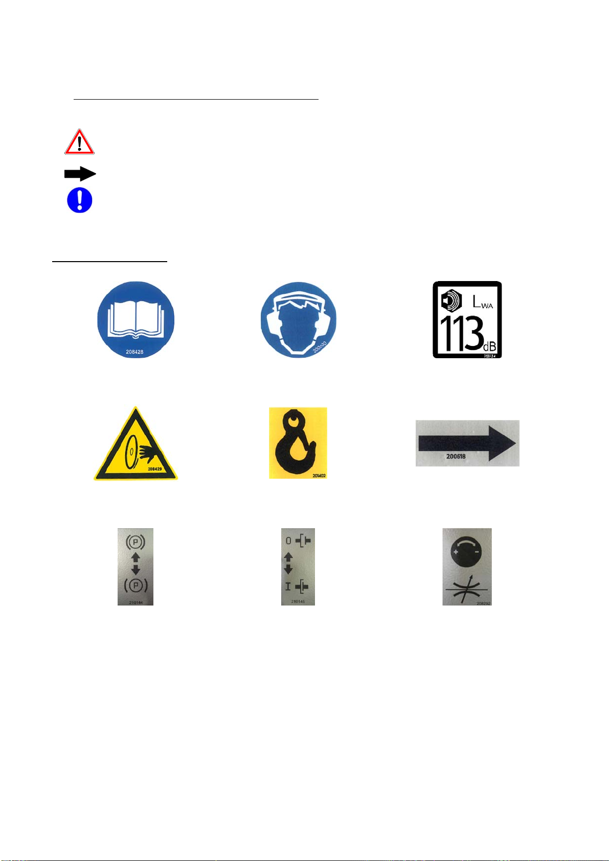
1.3.6 Observe all safety and danger instructions on the machine!
1.3.7 Keep all safety instructions and danger warnings on/in the machine
complete and in legible condition!
1.3.8 At the presence of safety-related changes to the machine or its running
behaviour, stop the machine immediately and report the problem to the
responsible post/person!
1.3.9 No changes, removal or addition of parts to the machine without the
approval of the supplier!
1.3.10 Only use original replacement parts from the manufacturer!
1.3.11 Observe required or prescribed deadlines given in the operating manual
for inspections!
1.3.12 Workshop equipment suitable for the work is absolutely necessary for
performing maintenance actions.

7
1.4 Personnel choice and personnel qualification; basic responsibilities
1.4.1 Work on the machine must only be performed by reliable personnel.
Observe the legal minimum age!
1.4.2 Only use trained or orientated personnel. Establish clear responsibilities
of the personnel for operating, changeover, servicing, and repairing the
machine!
1.4.3 Make sure that only authorised personnel work on the machine!
1.4.4 Establish the responsibility of the machine operator, also in respect to
traffic regulations, and enable him to refuse to follow instructions by third
parties that are contrary to safety!
1.4.5 Any personnel training, learning, being instructed, or currently involved in
general education may only work with the machine under the continual
supervision of an experienced person!
1.4.6 Work on the electrical equipment of the machine may only be carried out
by electricians or trained personnel under the management and
supervision of an electrician, and in accordance with the rules of
electronics.
1.5 Safety instructions for certain operation phases
1.5.1 Normal operation
1.5.1.1 Refrain from working in any manner that is questionable in regard to
safety!
1.5.1.2 Take measures to ensure that the machine is operated only in a safe,
functional condition!
1.5.1.3 At least once per shift check the machine for externally recognisable
damage and deficiencies! Any changes which occur (including operating
behaviour) must be reported immediately to the responsible post/person!
If necessary, immediately stop the machine and secure it!
1.5.1.4 Immediately stop and secure the machine in case of malfunctions!
Immediately correct malfunctions!
1.5.1.5 Before beginning work become familiar with the operating location and
working environment. The working environment includes, for example,
obstacles in the traffic area, bearing capacity of the floor, required
security of the construction site to the public traffic area and possibilities
for help in case of accidents.
1.5.1.6 You may not leave the floor cutter while the diesel motor is still running.
1.5.1.7 Do not leave the floor cutter with the brakes (Pos. 22) off.
1.5.1.8 When starting the diesel motor, the lever (Pos. 20) must always be in the
middle position.

8
1.5.2 Special work while using the machine and maintenance work as well as troubleshooting during
operation; disposal
1.5.2.1 Follow all setup, maintenance, and inspection activities and schedules
prescribed by the operating manual, including all information about the
replacement of parts / assemblies! These activities may only be carried
out by experts.
1.5.2.2 Inform operating personnel before beginning special and maintenance
work! Name a supervisor!
1.5.2.3 If the machine is completely turned off during maintenance and repair
work, it must be secured against unexpected application of power.
1.5.2.4 Before cleaning the machine with water or steam jet (high-pressure
cleaner) or other cleaning agents, cover/glue all openings in which no
water/steam/cleaning agent should penetrate due to safety and/or
functional reasons. Electric motor and switches are especially at risk.
1.5.2.5 After cleaning, remove the covers/tape completely!
1.5.2.6 During service and repair work, always tighten loose bolt joints!
1.5.2.7 If dismantling is required for fitting, servicing and repair, the safety fittings
must be remounted and checked immediately following the service and
repair work!
1.5.2.8 Please ensure the safe, environmentally friendly disposal of operating
and auxiliary materials and replacement parts!
1.6 Safety instructions for special types of dangers
1.6.1 Electric power
1.6.1.1 Use only original fuses with the specified current rating! In case of
problems with the electrical power supply, turn the machine off
immediately!
1.6.1.2 Work on the electrical operating equipment of the machine may only be
carried out by electricians or trained personnel under the management
and supervision of an electrician, and in accordance with the rules of
electronics.
1.6.1.3 The machine's electrical equipment must be inspected/checked regularly.
Faults such as loose connections or scorched cables must be corrected
immediately.
1.6.1.4 There is a high power draw when the ignition is active.
1.6.2 Dust
1.6.2.1 Follow applicable national regulations!
1.6.3 Noise
1.6.3.1 Wear specified personal hearing protection!

9
1.7 Transport
1.7.1 Only use lifting gear and load carrying equipment with sufficient lifting
capacity during loading work!
1.7.2 Name expert instructors for the lifting process!
1.7.3 Lift the machine only according to the instructions in the operating
manual (using attachment points for load-bearing systems, etc.), and with
proper lifting accessories!
1.7.4 Only use suitable transport vehicle with sufficient load capacity!
1.7.5 Secure loads reliably. Use suitable attachment points!
1.7.6 Even when moving the machine only for a short distance, disconnect the
machine from the power mains! Before restarting the machine, connect it
to the power mains correctly!
1.7.7 When recommissioning, follow the operating manual!
1.7.8 You may only move the floor cutter when the front part is slightly lifted.

10
2. Machine description
1.1 Component overview
Pos. 1 Steering wheel
Pos. 2 Control console
Pos. 3 Motor housing
Contents: Diesel engine, controls, hydraulic pump
Pos. 4 Steering rod
Pos. 5 Saw blade protective hood
Pos. 6 Water supply
Pos. 7 Undercarriage
Contents: Steering, gears
1.1 Safety guards
Pos. 5 Saw blade protective hood
30 261 2 19 20 6 2727.1
9 3 7 59 4
5

11
2.3. Technical data
MULTICUT 800 G MULTICUT 800 GH
Cut depth 315 mm (515 mm) 315 mm (515 mm)
Cutting depth setting Electrohydraulic / variable Electrohydraulic / variable
Standard saw blade Ø 800 mm (1,200 mm) 800 mm (1,200 mm)
Saw blade holder 35 mm (6x M12-TK 120 mm) 35 mm (6x M12-TK 120 mm)
Drive forwards 0 - 60 m/min 0 - 60 m/min
Drive backwards 0 - 25 m/min 0 - 25 m/min
Max. Output power 44 kW/ 60 PS 44 kW/ 60 PS
Saw blade speed Standard 1550 / 970 RPM 1550 / 970 RPM
Saw blade speed Optional 2500 / 1550 RPM 2500 / 1550 RPM
Saw blade drive V belt drive V belt drive
Dimensions (L/W/H mm) 1680 / 1050 / 1360 1680 / 1050 / 1360
Weight 935 kg 1070 kg
2.4. Noise parameters
Guaranteed noise power level:
MULTICUT 800 G MULTICUT 800 GH
113 dB(A) 113 dB(A)
Danger
Hearing protection must be worn when exceeding 85 dB(A)!
The noise emissions measurement was performed in
compliance with ISO 4872 DIN/ISO 6393 and DIN/ISO 6394.
2.5 Vibration on the steering shaft
Operating condition:
Measurement during concrete cutting
Blade diameter 1000m, Cutting depth 100mm
Total oscillation value
ahv = 5.47m/s²
The following standards were complied with during
measurement:
ISO 5349, DIN ENV 25349, DIN 45671, VDI 2057
The given values were measured during concrete cutting at a
cut depth of 10cm. In practice, these values are influenced by
the following conditions:
Quality of the saw blade
Weight of the operator
Feed speed
Condition of the machine
Concrete properties

12
2.6 Rotation speeds
MULTICUT 800 G
210693
Ø 500 – 800 mm Ø 700 – 1200 mm
rpm rpm rpm
2650 1550 970
2480 1450 910
2310 1350 850
2140 1250 780
1970 1150 720
MULTICUT 800 GH
210694
Ø 300 – 550 mm Ø 500 – 800 mm
rpm rpm rpm
2660 2500 1550
2550 2400 1450
2450 2300 1350
2340 2200 1250
2230 2100 1150
2.7 Water pressure
The water pressure in the lines to the floor cutter must not
exceed 5 bar.
Otherwise use a pressure reducer and reduce the water
pressure to max. 5 bar.

13
3. Commissioning
3.1 Control console
Before starting the floor cutter become familiar with its
operation.
11
14 15 16 17
19
18
20
21 2322 2413
10 2512
20.1

14
Pos. 10 Water temperature
Pos. 11 Motor oil pressure
may not burn during operation!
Pos. 12 Emergency stop switch
Pos. 13 Battery charging control
may not burn during operation!
Pos. 14 Fuses
Pos. 15 Plug sockets for lamps
Pos. 16 Water pump on-off
Pos. 17 Speed control for diesel motor
Pos. 18 Controller for forward speed cut-in movement of the saw
blade
Pos. 19 Saw blade "down" "up"
Pos. 20 Feed lever forwards - backwards
Pos. 21 Ignition switch
Pos. 22 Brake
Attention!
Movement only possible when the brakes are released!
Note
Only operate the brakes when the lever (Pos. 20) is in the
neutral position.
Lever lowered = brake released
Lever up = brakes locked
Pos. 23 Coupling for feed movement
Note
Only operate the coupling when the lever (Pos. 20) is in the
neutral position.
Lever up = feed inactive
Lever lowered = feed active
Pos. 24 Diesel motor speed
Pos. 25 Steering suspension

15
3.2 Connections and operating materials
The joint cutter is delivered filled with diesel fuel,
however this should be checked (see also 6.1.
Maintenance
All lubrication points are lubricated with Roxana ALU
EP2
HD system (Pos. 48)
Filling hole for diesel (Pos. 62)
Connect cooling water hose
3.3 Install saw blade
Danger!
Risk of injury!
Saw blade exchange may only be done with a shut down
motor (Pos. 21) and when the saw blade is at a standstill.
Switch on ignition (Pos. 21) but do not start the motor
Move the saw blade drive to the highest position using
the lever (Pos. 19).
Shut off the ignition (Pos. 21)
Disconnect the water hose
Remove exhaust hose (Pos 26)
(only MULTICUT 800 GH)
Unscrew the ring screw (Pos. 27) and remove the Y-
piece from the holder
Unscrew the M 10 (Pos. 27.1) ring nut
Remove the saw hood (Pos. 5)
Loosen the hexagon head screw (left-hand thread)
Remove the pressure disc
Insert the saw blade
Attention!
Ensure that the flange surfaces are clean.
Match the direction of rotation of the saw blade (arrow on the
blade) with the arrow on the saw hood (synchronised sawing).
Mount the pressure disc and fasten using the screws
(use force to tighten)
Replace the protective hood
Mount the ring screw (Pos. 27.1)
Place the Y hose piece into the holder and tighten it with
the ring screw (Pos. 27)
Mount the exhaust hose (Pos. 26)
(only MULTICUT 800 GH)
Connect the water hose

16
3.4 Preparations for starting
Move the floor cutter into position
Steering rod (Pos. 4) and saw blade (or rear steering rod)
are above the cut line
Note
The feed lever (Pos. 20) must be in the middle position when
starting the motor.
Start the diesel motor (Pos. 21)
Attention!
Follow the Kubota operating manual!
Release the brakes (Pos. 22) and connect the feed
(Pos. 23)
Open water tap (Pos. 9)
Note
Take the rotation speed from the table (see 2.6) and follow the
rev counter (Pos. 24)!
Set the rotation speed above the gas lever (Pos. 17)
Reduce the controller (Pos. 18) (clockwise)
Slowly lower the saw blade using the toggle lever (Pos.
19) and controller (Pos. 18) - until it cuts slightly.
Attention!
Is the saw blade getting enough cooling water?
Set the depth display (Pos. 30) to "zero".
Immerse the saw blade to the desired cut depth
* Toggle lever (Pos. 19) and controller (Pos. 18)
* Observe the depth display (Pos. 30)
Feed movement is controlled with the lever (Pos. 20).
Max. forward movement speed = max. lever travel
3.5 Feed lever stopper
The adjustable feed lever stopper (Pos. 20.1) enables a
consistent feed.
20
20.1

17
4. Transport
4.1 Movement
Attention!
Floor cutter movement is only permitted with a stationary
saw blade.
For the MULTICUT 800, the saw blade must be removed!
For MULTICUT 800 G and MULTICUT 800 GH the drive lever
(Pos. 40) must be in the STOP position!
Attention!
Release the brakes (Pos. 22) and activate the feed (Pos. 23)
Switch on the ignition (Pos. 21) but do not start the diesel
motor
Slightly lift the floor cutter forwards using the toggle
switch (Pos. 19)
Start the diesel motor using the ignition (Pos. 21)
Introduce movement using the feed lever (Pos. 20)
4.2 Moving with the crane
Danger!
Personnel should never remain under hanging loads! Comply
with the load carrying capacity of the sling material!
Place the floor cutter onto the crane eye (Pos. 31)
Lift carefully and observe the weight distribution
Always keep an eye on the floor cutter
4.3 Set down manually
Danger!
Manual set down onto inclines or declines is forbidden!
Secure the floor cutter against roll away.
Release brakes (Pos. 22)
Release coupling (Pos. 23)
Move the feed lever (Pos. 20) forwards
Move the floor cutter slightly upwards with the toggle
lever (Pos. 19)
Push the floor cutter to the housing

18
5. Operation
5.1 Normal cutting operation
Preparations for starting (see 3.4)
The feed speed is controlled using the feed lever (Pos.
20)
5.2 Cooling water
Make sure that the saw blade is supplied with sufficient
cooling water. The lifetime and the cutting performance are
influenced by this.
Use only clean water
Do not kink water hose
5.3 Saw blade selection
Danger!
No mesh discs may be used.
Refer to the prospect “Lissmac Diamond Tools”.
Install only saw blades recommended by the manufacturer.
5.4 Cutting depth limits
This setting is recommended for several cuts of the same
depth
Immerse to the desired cut depth
Toggle lever (Pos. 19)
Controller (Pos. 18)
Screw in the stop screw (Pos. 38) to the stopper
(clockwise) and lock with a nut.
5.5 Switching from counter rotation to parallel feed cutting
Attention!
Switching can only be done when at standstill
If there is danger of frost, the gears under the water tap (Pos.
41) must have water removed.
Switch off the motor at the ignition switch (Pos. 21)
Place the lever (Pos. 40) into position
40
Left position = counter clockwise
Middle position = STOP
Right position = clockwise

19
5.6 Change from right to left cut
The waste water suction (Pos. 32) must be removed (see
5.8.4)
Remove the protective hood and saw blade (see 3.3)
Remove the safety cover (Pos. 50.5) on the saw blade
shaft
Mount the saw blade (see 3.3)
Replace the saw blade protective hood
Mount the water supply (Pos. 6)
Turn the steering rod (Pos. 4)
* Swing the steering wheel out
(only MULTICUT 800 GH)
* Mount the feed lever (Pos. 20) to the adapter (Pos. 36)
(only MULTICUT 800 GH)
Mount the waste water suction (Pos. 32) on the floor cutter
(see 5.8.4).
5.7 Changing the saw blade speed (also see 6.9)
Standard speed is 1550 1/min v-belt (Pos. 58.4)
Remove the guard plate (Pos. 50)
Disconnect water supply (only for MULTICUT 800 GH
and GH or accessories) on the saw blade shaft
Loosen screws (Pos. 57) (left and right)
Release the tension on the V-belts using screw pos. 58
(left and right)
Loosen and remove nuts (Pos. 58.1) and fold clamps
(Pos. 58.3) down
Fold up both holders (Pos. 58.2)
Set down the saw blade shaft into the holders (Pos. 58.2)
Remove V-belts (Pos. 58.4)
Install additionally delivered V-belts in pos. 58.5 (speed
970 1/min)
Installation of the saw blade shaft in reverse order
Attention!
Tension the V-belt equally - follow the scale (Pos. 58.6) on
both sides.
5.8 Setting the steering suspension (Pos. 25)
Using only one-sided cutting resistance it is not possible to
operate the joint cutter in a straight line without steering in the
opposite direction. When you have reached the proper
opposite steering amount, the steering can be set using the
lever (Pos. 25).

20
58.2 46
47
58
57
58.6
58.4 53 52 58.4
47 58.558.3 51
47
58.5
58.1
58.3
Table of contents
Other Lissmac Cutter manuals