Spedo 2600 User manual
1 | S p e d o 2 6 0 0 O p e r a t o r M a n u a l S p e d o U K L t d
1 Spedo 2600 Pinless Forms Cutter Operator Manual
Spedo 2600 Pinless Forms Cutter
Operator Manual
Issue 5
Part Number SP 007 005
Spedo UK Limited
76 Woolmer Way
Bordon
ampshire
GU35 9QF
ENGLAND
Telephone: +44 (0) 1420 487 447
Fax: +44 (0) 1420 477 827
Web: www.spedouk.com

2 | S p e d o 2 6 0 0 O p e r a t o r M a n u a l S p e d o U K L t d
2 Spedo 2600 Pinless Cutter Operator Manual
Spedo 2600 Pinless Forms Cutter
History Sheet
Manual Issue Date Changes Incorporated
1
March
2012
First dition
2
January 2013
Change of Address
3
July 2013
Correcti
on of Specifications
4
May 2015
Addition of new functions
5
May 2015
Changed Format

3 | S p e d o 2 6 0 0 O p e r a t o r M a n u a l S p e d o U K L t d
3 Spedo 2600 Pinless Cutter Operator Manual
Spedo 2600 Pinless Forms Cutter
Publisher
Published by Spedo U Limited
76 Woolmer Way
Bordon
Hampshire
GU35 9QF
ENGLAND
Copyright
Spedo U Limited 2012
All Rights Reserved.
No part of this publication may be reproduced, stored in a retrieval system, or
transmitted, in any form or by any means, electronic, mechanical, photocopying,
recording, or otherwise, without the prior written permission of Spedo U Limited.
Unpack
Unpack the equipment and examine it thoroughly to ascertain whether any damage
has occurred in transit. Report immediately any such damage to the agent or
manufacturer. Retain the packing should further transportation be necessary.
All oods
All goods manufactured by the Company are guaranteed to the extent hereafter
mentioned against defects arising from faulty material or workmanship subject to
the goods not having suffered maltreatment or interference. The Company's liability
under this guarantee is limited to replacing any part or parts found defective within
a period as laid down in Company instructions after the date of delivery or
installation.
Other oods
If goods not of the Company's manufacture are ordered, the guarantee of that
company is to be accepted
.
Descriptive Matter
Descriptive matter, illustrations, dimensions and weights issued by the Company are
typical and shall not be held as binding
.
Patterns and Designs
The Company reserves the right to alter patterns and designs without notice
.
First Published
March 2012
We have taken every care in the preparation of this manual. If there are any
inaccuracies, ambiguities or omissions, Spedo U Limited and its consultants and
distributors cannot accept responsibility for any loss or damage these errors may
cause
.

4 | S p e d o 2 6 0 0 O p e r a t o r M a n u a l S p e d o U K L t d
4 Spedo 2600 Pinless Cutter Operator Manual
Spedo 2600 Pinless Forms Cutter
Safety Measures
This instruction manual contains certain WARNING and CAUTION notices which must be
followed by the user to ensure safe operation and to retain the equipment in a SAFE condition.
All users of the equipment described in this manual MUST have received adequate training in its
use and application in order to ensure SAFE AND PROPER USE.
Any adjustment, maintenance or repair of the opened apparatus under voltage shall be carried
out only by a skilled person who is AWARE OF THE HAZARD INVOLVED.

5 | S p e d o 2 6 0 0 O p e r a t o r M a n u a l S p e d o U K L t d
5 Spedo 2600 Pinless Cutter Operator Manual
Spedo 2600 Pinless Forms Cutter
Table of Contents
History Sheet ................................................................................................................... 2
Copyright ......................................................................................................................... 3
Safety Measures .............................................................................................................. 4
Table of Contents ............................................................................................................ 5
ENERAL DESCRIPTION SECTION 1
INTRODUCTION .......................................................................................................... 7
TECHNICAL DATA ........................................................................................................ 8
DESCRIPTION OF OPERATION .................................................................................... 9
Spedo 2600 Forms Cutter ...................................................................................... 9
Operation with Web Control Units ...................................................................... 10
Operation with a Printer or Unwinder ................................................................ 10
Operation with a 9400 ......................................................................................... 11
MODES OF CUT ......................................................................................................... 12
Introduction ......................................................................................................... 12
Setting the Form Depth ....................................................................................... 14
Setting the Strip Depth in Dual Cut Mode ........................................................... 18
APPENDIX A1 Optional Accessories ......................................................................... 19
APPENDIX A2 Residual Current Device .................................................................... 20
COMMISSIONIN THE SYSTEM SECTION 2
INTRODUCTION ........................................................................................................ 21
UNPAC .................................................................................................................... 21
ACCESSORIES ............................................................................................................ 21
SITE CONSIDERATIONS ............................................................................................. 21
INSTALLATION .......................................................................................................... 21
Connecting the Mains (Power) Lead ................................................................... 21
Installation Checks ............................................................................................... 22
OPERATIN INSTRUCTIONS SECTION 3
SUMMARY OF CONTROLS ........................................................................................ 24
Paper Transport deck .......................................................................................... 24
Control Panel ....................................................................................................... 24
OPERATING PROCEDURE .......................................................................................... 25
Summary of Controls - Pushbuttons ............................................................... 25
Paper Loading ...................................................................................................... 26
Operation from the Control Panel ....................................................................... 26
Preliminary Manual Cut Operation ................................................................. 27
Start Continuous Operation ............................................................................ 27
Stop Continuous Operation ............................................................................ 27
Emergency Stop Operation ............................................................................. 27
Paper Run-out ................................................................................................. 28
Loading the Paper Web .................................................................................. 29

6 | S p e d o 2 6 0 0 O p e r a t o r M a n u a l S p e d o U K L t d
6 Spedo 2600 Pinless Cutter Operator Manual
Lowering and Adjusting the Pressure Wheel.................................................. 30
Setting Side Trimmers ..................................................................................... 32
Setting Centre Cutter ...................................................................................... 33
OPERATOR PANEL INSTRUCTIONS ........................................................................... 25
Mode Selection .................................................................................................... 34
Creating a Job ...................................................................................................... 35
Editing a Job ......................................................................................................... 36
Optical Mark Recognition (OMR) Operation ....................................................... 37
Enabling / Disabling the OMR Sensor .................................................................. 39
Adjusting the OMR Sensor .................................................................................. 41
Counter / Batch Mode Operation ....................................................................... 42
Maximum Speed Operation ................................................................................ 44
User Menu Settings ............................................................................................. 45
Maintenance and Engineers Mode ..................................................................... 47
Changing the Blade Setup ................................................................................... 48
Parts Catalogue .................................................................................................... 49
OPERATIONAL MAINTENANCE SECTION 4
WARNINGS ............................................................................................................... 50
CLEANING ................................................................................................................. 50
LUBRICATION ............................................................................................................ 51
7 | S p e d o 2 6 0 0 O p e r a t o r M a n u a l S p e d o U K L t d
7 Spedo 2600 Pinless Cutter Operator Manual
ENERAL DESCRIPTION SECTION 1
INTRODUCTION
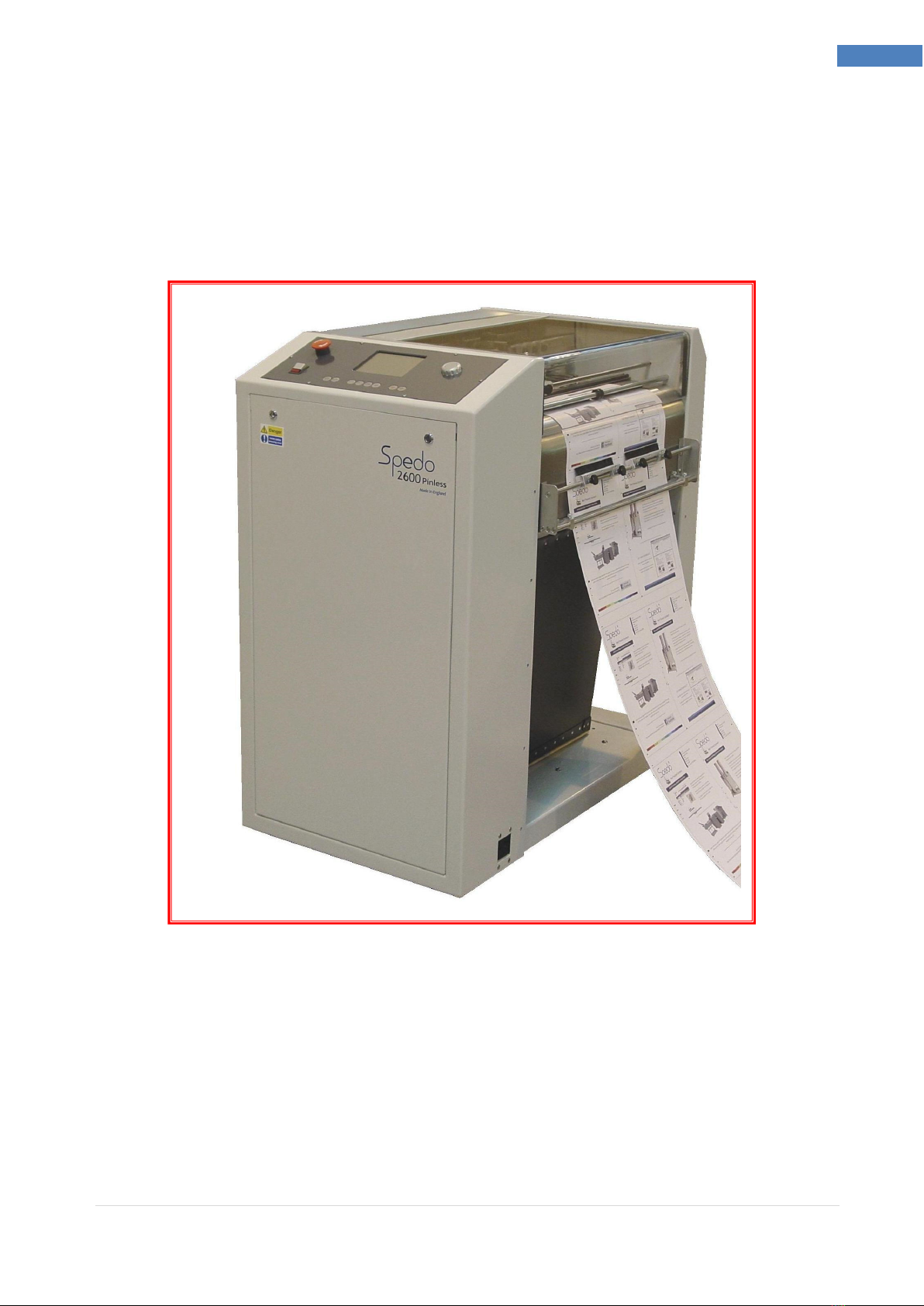
The Spedo 2600 Pinless Forms Cutter is designed to produce cut sheets from continuous paper
webs. In addition, the machine can also optionally trim away either or both margins and
optionally centre cut the paper web.
Fig . Spedo 2600 Pinless Forms Cutter
A normal cross-cut is made at the leading edge of the paper web. However, the machine is also
capable of operating in double cross-cut mode, when it is required to cut before and after the
leading edge to shorten the overall length of the form.
The depth of form to be cut, depth of strip and feed are all measured in terms of line increments,
either as a 6 lines per inch, 8 lines per inch, 10 lines per inch, 12 lines per inch or 16 lines per inch.
In double cut mode, a second cross-cut is made at any interval of between 1 to 9 lines after the
first cut as set by the digital coding switch.

8 | S p e d o 2 6 0 0 O p e r a t o r M a n u a l S p e d o U K L t d
8 Spedo 2600 Pinless Cutter Operator Manual
TECHNICAL DATA
Basic Design:
The standard machine comprises the operator’s panel, 2 tractor
units with width adjustment by hand wheel, LH & RH edge (margin)
trimmers, noise absorbing protective cover, & paper guides.
EMC Conformity:
The electrical equipment incorporated in this machine with EMC
Directive (89/336/EEC amended by 91/236/EEC and 92/31/EEC),
TUV Rheinland Certification & CE Certification.
Finish:
Spedo white main frame with graphite grey operator panel.
Modes of Cut:
Normal single cut, double (strip) cut or Twin-cut operation.
Paper Weight:
Single Web: 40 g/m
2
to 300 g/m
2
.
Performance:
Form Depth S/Cut 1/6 Strip Cut Twin cut
14 inch 22,320 14,880
12 inch 24,480 15,840 19,680
11 inch 25,920 16,440
10 inch 27,480 17,040
8 inch 31,080 18,360
7 inch 32,760 19,080
6 inch 35,400 20,040
4 inch 42,000 21,120
3 inch 42,120 21.240
Line Feed Increments:
1/6 in, 1/8 in, 1/10 in, 1/12 in, 1/16 in or millimetres
Form Width:
145 mm - 482 mm (5 ¾ - 19inches)
Form Depth:
64mm – 700mm (2 ½ inch – 27 ½ inch)
Strip Cut:
1mm – 38mm (1/32 inch – 1 ½ inch)*
*Subject to stock weight and production speed.

9 | S p e d o 2 6 0 0 O p e r a t o r M a n u a l S p e d o U K L t d
9 Spedo 2600 Pinless Cutter Operator Manual
Width of Continuous Web:
510 mm (20inches)
Feed Speed:
Rotary control, continuously adjustable.
Counter Type:
Integrated multifunction batch counter.
Power Requirements:
Voltage: 230 V +/-10%
Frequency: 50 Hz to 60 Hz.
Power Consumption: 690 W (approx).
Noise Emissions:
69dB
Dimensions:
Length: 575 mm.
Width: 980 mm.
Height: 1070 mm.
Weight:
140 kg (approx).
Options
Options are listed in Appendix A1 to this section.
DESCRIPTION OF OPERATION
Spedo 2600 Pinless Forms Cutter
Paper is fed into the machine under the paper tension brush, over the in-feed plate, along the paper
supports onto two paper guide units. Once the paper guide units have been adjusted for width and
thickness (weight) of paper web, the web is `jogged' forward and backwards by the operator until it has
been aligned with the edge of the paper guide unit flaps.
At this stage, if the carrier sides (margins) are to be cut off, LH and RH trimmers can be engaged, their
precise position being set by aligning their cut marks with the carrier perforations. In addition, a centre
cutter can be engaged and aligned by the operator at this point, if required.
The machine is capable of operating in conjunction with an ancillary unit (e.g. a web control, printer or
labeller) and successful co-operation between the two units depends on the loop of paper that forms
between the two machines. The presence of paper feeding into the machine is detected by a paper run
out switch located on the in-feed plate. If the paper runs out, the machine automatically stops.
10 | S p e d o 2 6 0 0 O p e r a t o r M a n u a l S p e d o U K L t d
10 Spedo 2600 Pinless Cutter Operator Manual
Operation with Web Control Devices.
It is possible to run the 2600 Pinless Forms Cutter In-Line with a variety of input devices. Depending on the
speed and application of the input device the correct interface unit can be configured using the examples
below.
Spedo 2230 Optical Loop Switch.
Fig1.2
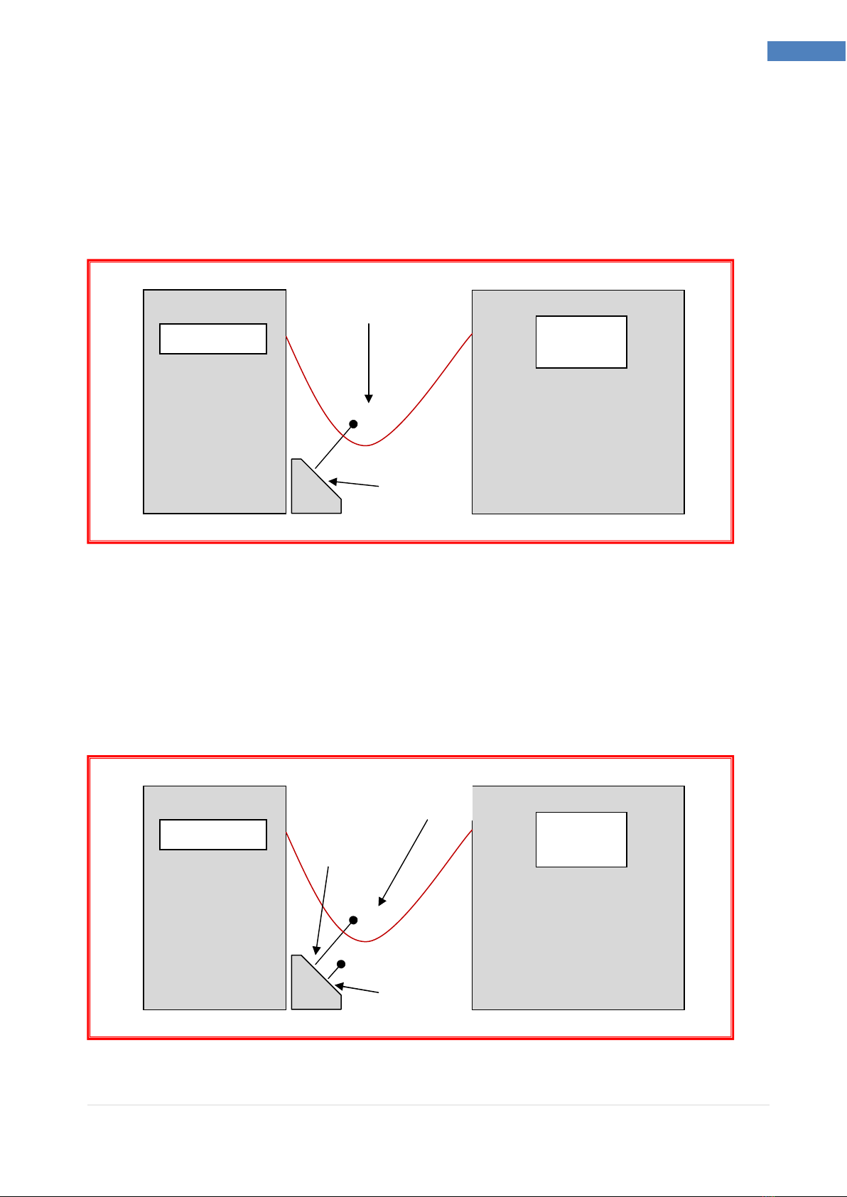
Operation with a Printer or Unwinder
When the machine is being supplied from a printer or unwinder which has no means of controlling its out-
feed, it will be necessary to control the paper loop height by positioning either a Spedo Optical Loop
Switch Unit or an Optical Loop Interface Unit between the machine and the printer or unwinder as shown
in Figs 1.2 & 1.3.
Spedo 2231 Optical Loop Interface.
Fig .3
2600 Cutter
Printer or
Unwinder
2600 Cutter
Printer or
Unwinder
P
APER
L
OOP
S
ENSING
A
REA
C
UTTER
S
TOP
S
ENSOR
P
APER
L
OOP
S
ENSING
A
REA
P
RINTER
S
TOP
S
ENSOR
C
UTTER
S
TOP
S
ENSOR

11 | S p e d o 2 6 0 0 O p e r a t o r M a n u a l S p e d o U K L t d
11 Spedo 2600 Pinless Cutter Operator Manual
Spedo 9400 Web Control Unit.
The Spedo 9400 Web Buffer is an interface unit designed to allow the Spedo 2600 pinless forms cutter to
be run in line with high speed continuous forms printers and unwinders.
The 9400 is able to pause both the cutter and the printer or unwinder as needed, as well as being able to
speed up and slow down to match the speed of the input device.
Fig .4
2600 Cutter Printer or
Unwinder
9400 Web
Buffer
U
LTRASONIC SENSOR
DETECTS WEB EIG T
TO CONTROL INPUT
12 | S p e d o 2 6 0 0 O p e r a t o r M a n u a l S p e d o U K L t d
12 Spedo 2600 Pinless Cutter Operator Manual
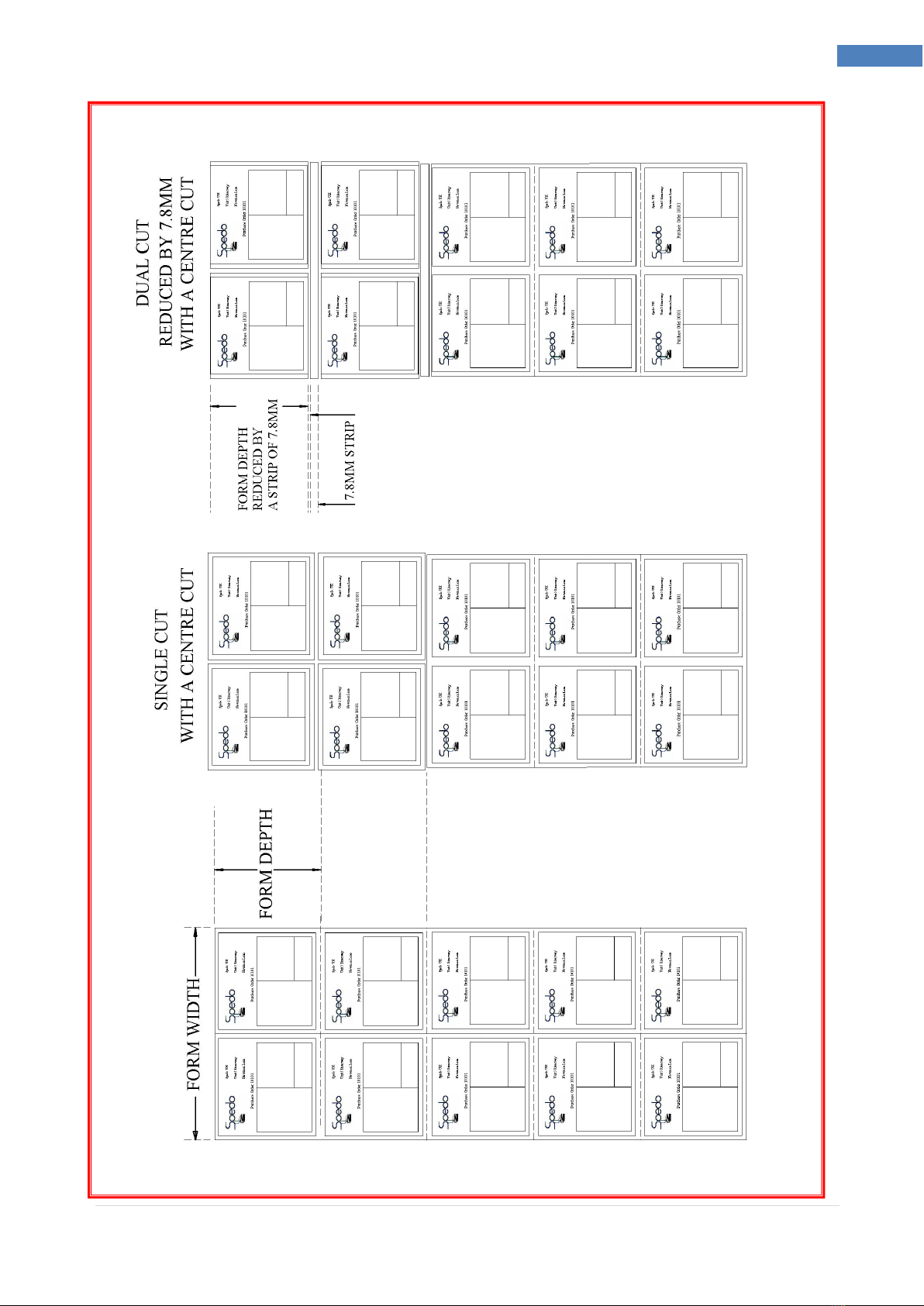
MODES OF CUT
Introduction
Forms can be cut either by a single cut or by a dual (double) cut as configured by the digital coding switch.
The terminology used in the following explanation relates to Fig 1.5.
Single cut mode is used when it is required to make the cut at the leading edge of the paper web as
shown. The value of form depth is set on the digital code switch on the control panel.
Modes of Cut – Single Cut
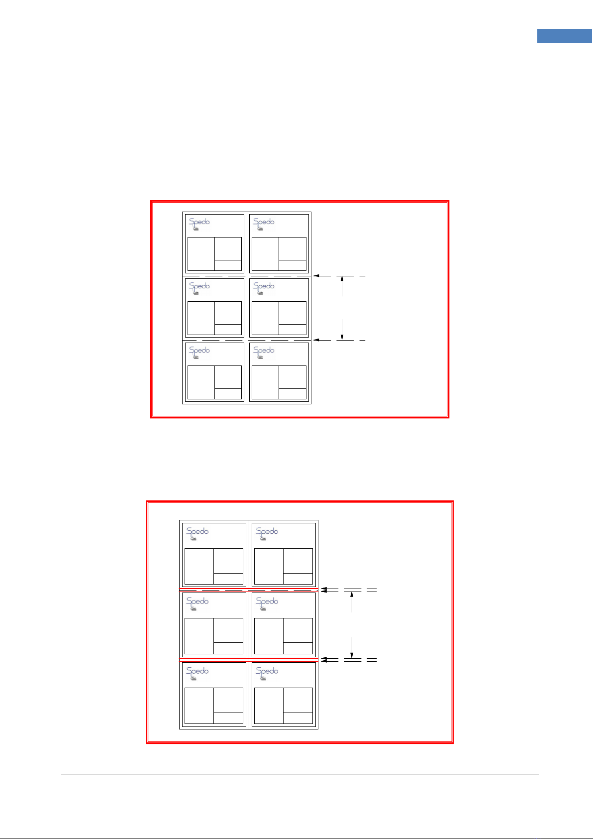
Dual cut mode is used when the cut form depth required is smaller than the depth of the original stock
size as shown below, this results in a strip being cut away between forms. In this mode, the value of the
form depth and the strip depth is set in on the digital code switch on the control panel.
Modes of Cut – Dual Cut
FORM
DEPT
SINGLE
CUT ERE
SINGLE
CUT ERE
Spedo UK
Unit 5 Riverwey
Newman Lane
Alton, ampshire
GU34 2QL
Purchase Order 10101
Spedo UK
Unit 5 Riverwey
Newman Lane
Alton, ampshire
GU34 2QL
Purchase Order 10101
Spedo UK
Unit 5 Riverwey
Newman Lane
Alton, ampshire
GU34 2QL
Purchase Order 10101
Spedo UK
Unit 5 Riverwey
Newman Lane
Alton, ampshire
GU34 2QL
Purchase Order 10101
Spedo UK
Unit 5 Riverwey
Newman Lane
Alton, ampshire
GU34 2QL
Purchase Order 10101
Spedo UK
Unit 5 Riverwey
Newman Lane
Alton, ampshire
GU34 2QL
Purchase Order 10101
FORM
DEPT
DUAL
CUT ERE
DUAL
CUT ERE
Spedo UK
Unit 5 Riverwey
Newman Lane
Alton, ampshire
GU34 2QL
Purchase Order 10101
Spedo UK
Unit 5 Riverwey
Newman Lane
Alton, ampshire
GU34 2QL
Purchase Order 10101
Spedo UK
Unit 5 Riverwey
Newman Lane
Alton, ampshire
GU34 2QL
Purchase Order 10101
Spedo UK
Unit 5 Riverwey
Newman Lane
Alton, ampshire
GU34 2QL
Purchase Order 10101
Spedo UK
Unit 5 Riverwey
Newman Lane
Alton, ampshire
GU34 2QL
Purchase Order 10101
Spedo UK
Unit 5 Riverwey
Newman Lane
Alton, ampshire
GU34 2QL
Purchase Order 10101
13 | S p e d o 2 6 0 0 O p e r a t o r M a n u a l S p e d o U K L t d
13 Spedo 2600 Pinless Cutter Operator Manual
14 | S p e d o 2 6 0 0 O p e r a t o r M a n u a l S p e d o U K L t d
14 Spedo 2600 Pinless Cutter Operator Manual
Setting the Form Depth
The principle of setting form depth is by line count. The machine motor is geared such that 1 revolution of
the drive roller moves the paper web forward exactly 6 inches.
For single cut mode, the Strip Depth switch is always set to 0 and can be ignored during the following
explanation.
In order to allow the operator to set various form depth values (6, 12, 18 inches etc..) by line increment,
the machine is fitted with a line increment feature that allows the cut to be made at line positions. The
incremental values can be selected at the Increment switch and are as follows:
1/6 in = 6 lines per inch
1/8 in = 8 lines per inch
1/10in = 10 lines per inch
1/12 in = 12 lines per inch
1/16 in = 16 lines per inch
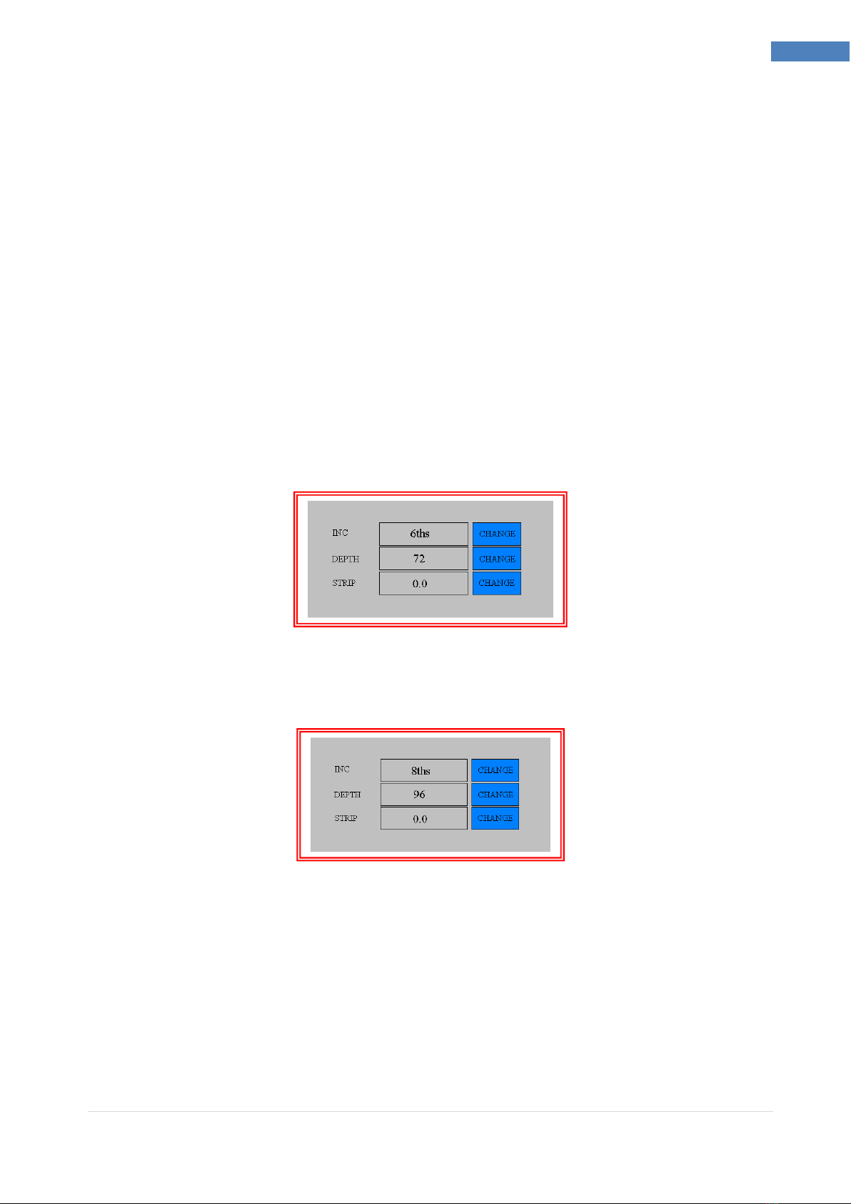
From the above table, it can be seen that if you wished to cut to a form depth of 12 inches, if you selected
a line increment of 1/6 in, this would be 6 lines x 12 inches = 72 lines.
So you would dial up 072 on the Form Depth switch. The machine would then cut at each 72 line point.
Similarly, if you selected 1/8 in line increment, this would be 8 lines x 12 inches = 96 lines.
So you would dial up 096 on the Form Depth switch and the machine would then cut at each 96 line point
and still maintain the 12-inch form depth.

15 | S p e d o 2 6 0 0 O p e r a t o r M a n u a l S p e d o U K L t d
15 Spedo 2600 Pinless Cutter Operator Manual
Example 1. If you wished to cut a form of depth 11
1
/
4
inches from a continuous paper web, the line
increment set-in must be a multiple of the denominator of the fractional value (in this example it is 4). 4 is
a multiple of 8, 12 or 16, so either of these incremental values can be set to give a round number of total
lines per form depth:
With 1/8 in selected = 8 lines per inch,
8 x 11 = 88
8/4 = 2 lines
88 + 2 = 90 lines.
The values set on the digital code switches would be 8 090.
With 1/12 in selected = 12 lines per inch,
12 x 11 = 132 lines
12/4 = 3
132 + 3 = 135 lines
The values set on the digital code switches would be 12 135.
With 1/16 in selected = 16 lines per inch,
16 x 11 = 176 lines
16/4 = 4
176 + 4 = 180 lines
The values set on the digital code switches would be 16 180.

16 | S p e d o 2 6 0 0 O p e r a t o r M a n u a l S p e d o U K L t d
16 Spedo 2600 Pinless Cutter Operator Manual
Example 2. If you wished to cut a form of depth 10 1/2 inches from a continuous paper web, the line
increment set-in must be a multiple of the denominator of the fractional value (in this example it is 2).
2 is a multiple of 6, 8, 12 or 16, so either of these incremental values can be set to give a round number of
total lines per form depth:
With 1/6 in selected = 6 lines per inch,
6 x 10 = 60 lines
6/2 = 3
60 + 3 = 63 lines
The values set on the digital code switches would be 6 063.
With 1/8 in selected = 8 lines per inch,
8 x 10 = 80 lines
8/2 = 4
80 + 4 = 84 lines.
The values set on the digital code switches would be 8 084.
With 1/10 in selected = 10 lines per inch,
10 x 10 = 100 lines
10/2 = 5
100 + 5 = 105 lines.
The values set on the digital code switches would be 10 105.
With 1/12 in selected = 12 lines per inch,
12 x 10 = 120
12/2 = 6
120 + 6 = 126 lines.

17 | S p e d o 2 6 0 0 O p e r a t o r M a n u a l S p e d o U K L t d
17 Spedo 2600 Pinless Cutter Operator Manual
The values set on the digital code switches would be 12 126.
With 1/16 in selected = 16 lines per inch,
16 x 10 = 160 lines
16/2 = 8
160 + 8 = 168 lines.
The values set on the digital code switches would be 16 168.
Example 3. If you wished to cut a form of depth 7
1
/
5
inches from a 12-inch continuous paper web, the line
increment set-in must be a multiple of the denominator of the fractional value (in this example it is 5).
5 is a multiple of 10, so only an incremental value of 10 can be set to give a round number of total lines
per form depth:
With 1/10 in selected = 10 lines per inch,
10 x 7 = 70 lines
10/5 = 2
70 + 2 = 72 lines.
The values set on the digital code switches would be 10 072.
18 | S p e d o 2 6 0 0 O p e r a t o r M a n u a l S p e d o U K L t d
18 Spedo 2600 Pinless Cutter Operator Manual
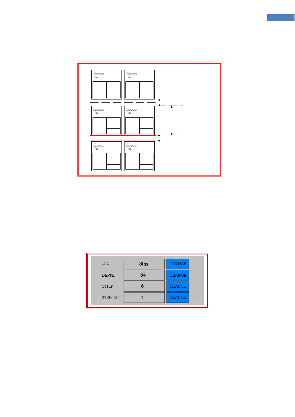
Setting the Strip Depth in Dual Cut Mode
When in dual cut mode, the machine makes a cut immediately before and after a perforation, resulting in
a strip being cut out. The strip depth value is set in terms of line increment on the Strip Depth switch.
Consider Example 1 again. A form depth of 11
1
/
4
is to be cut from a 12-inch web:
12 - 11
1
/
4
=
3
/
4
.
This means that a 3/4 inch strip must be cut out between forms. A
3
/
4
inch depth at a line increment of 1/8
in works out as|:
8/4 = 2
2 x 3 = 6 lines.
With the value 6 set on the Strip Depth switch, 6 must be deducted from the original value of 90 set in for
a single cut, so that 84 is now set-in on the Form Depth switch.
The Strip Depth switch can be set in the range 0 to 9 (lines) and these will relate to the line increment
setting selected.
The cut positions can now be `fine tuned' by the using the JOG pushbuttons to determine how many lines
before and after the perforation line the cuts are made ( i.e., 3 lines before and 3 lines after, or 1 line
before and 5 lines after, etc.)
Multiple strips can also be performed by increasing the STRIP[X] multiplier function.
11 1/4 "
FORM DEPT
3/4 " STRIP
3/4 " STRIP
Spedo UK
Unit 5 Riverwey
Newman Lane
Alton, ampshire
GU34 2QL
Purchase Order 10101
Spedo UK
Unit 5 Riverwey
Newman Lane
Alton, ampshire
GU34 2QL
Purchase Order 10101
Spedo UK
Unit 5 Riverwey
Newman Lane
Alton, ampshire
GU34 2QL
Purchase Order 10101
Spedo UK
Unit 5 Riverwey
Newman Lane
Alton, ampshire
GU34 2QL
Purchase Order 10101
Spedo UK
Unit 5 Riverwey
Newman Lane
Alton, ampshire
GU34 2QL
Purchase Order 10101
Spedo UK
Unit 5 Riverwey
Newman Lane
Alton, ampshire
GU34 2QL
Purchase Order 10101

19 | S p e d o 2 6 0 0 O p e r a t o r M a n u a l S p e d o U K L t d
19 Spedo 2600 Pinless Cutter Operator Manual
OPTIONAL ACCESSORIES APPENDIX A1
Double Cross-Cut Blade
This is a cross-cutting device for removing the cross perforation from the paper web, without any
loss of time or performance. The strip depth can be changed from 1/6
th
to 7.8mm.depending on
the size of blade to be fitted. The strip is cleanly separated from the forms on each motion of the
blades by blown air. The movable lower blade can be tilted off for single cut operation, if
required. In this mode, the Strip Depth switch on the control panel will be removed.
Optical Loop Switch Unit 2230
This unit is designed to control the height of the paper loop which forms between an out-feeding
printer or collator and the associated in-feeding Spedo Forms Cutter.
Optical Loop Interface Unit 2232
This unit is designed to control the height of the paper loop that forms between an out-feeding
printer or collator and the associated in-feeding Spedo Forms Cutter. It also detects the overflow
of paper out-feeding from the printer or collator that occurs if the Forms Cutter stops accepting
paper infeed.
Web Control Unit 9400
This unit is a high speed web buffer used to accurately control the paper web into the forms
cutter. The web buffer allows the operator to stop and start the entire print line automatically,
thus improving productivity.
Side Strip Chopper
This is used for shredding the cut-off side strip which is collected in a metal tray.
Anti-Static Kit
This is supplied with mounting accessories to remove static built up from the laser printing
process.
Centre Cutters
Additional Centre Cutter Assemblies can be fitted, providing additional longitudinal cuts along the
paper web.
Additional Accessories
Stack Tray & Paper Stops

20 | S p e d o 2 6 0 0 O p e r a t o r M a n u a l S p e d o U K L t d
20 Spedo 2600 Pinless Cutter Operator Manual
RESIDUAL CURRENT DEVICE APPENDIX A2
USE OF RESIDUAL CURRENT DEVICE (RCD)
As part of its highly reliable cutting mechanism, the Spedo 2600 Pinless Forms Cutter uses
brushless AC servomotors. These servomotors use a high frequency switching current. If it is
necessary to use a Residual Current Device with your system, it must be a unit that has been
specified for inverter use.
Spedo U recommends that only RCDs provided by Spedo U are used. Spedo U will not accept
any responsibility for a system failure if an RCD from another supplier is used.
Two versions are available:
Part No. SP005 376 Residual Current Device, c/w Cord Set.
Part No. SP005 377 Residual Current Device, Wall Mounted.
Other manuals for 2600
1
Table of contents
Other Spedo Cutter manuals


