MetalMaster SG-420 User manual

HYDRAULIC GUILLOTINE
OPERATION MANUAL
Edition No :SG-4281-1
Date of Issue :06/2019
Models.
SG-420, SG-815H
Order Code S535, Order Code S537
22/07/2019
Instructions Manual for SG-420 (S535)
1
2
OPERATION MANUAL
NOTE:
In order to see the type and model of the machine, please see the
specication plate. Usually found on the back of the machine. See
example (Fig.1)
Fig.1
HYDRAULIC GUILLOTINE
MACHINE
MODEL NO.
SERIAL NO.
DATE OF MANF.
Note:
This manual is only for your reference. Owing to the continuous improvement of the
Metalmaster machines, changes may be made at any time without obligation or notice.
Please ensure the local voltage is the same as listed on the specication plate before
operating any electric machine.
Distributed by
www.machineryhouse.co.nz
MACHINE DETAILS
22/07/2019
Instructions Manual for SG-420 (S535)
2
3
OPERATION MANUAL
C O N T E N T S:
1. GENERAL MACHINE INFORMATION
1.1 Specications.................................................................... 4
1.2 Standard Equipment...................................................... 4
1.3 Identication..................................................................... 5
2. IMPORTANT INFORMATION
2.1 General Metalworking Machine Safe Practices.... 6
2.2 Safe Work Procedure Metal Cutting Guillotine..... 8
2.3 Lifting Instructions.......................................................... 9
3. INSTALLATION
3.1 Site Preparation and Installation................................. 10
3.2 Machine Leveling............................................................. 11
3.3 Attaching The Accessories........................................... 11
3.4 Electrical Installation....................................................... 14
3.5 Full Load Current............................................................. 14
3.6 Filling The Oil Tank.......................................................... 15
4. COMMISSIONING
4.1 Preparation of the Machine......................................... 16
4.2 Safety Sensor Alignment.............................................. 16
4.3 Controls............................................................................... 19
4.4 Commissioning Check List........................................... 20
5. OPERATION INSTRUCTION
5.1 Pre-Operational Safety Check Before Operating. 20
5.2 Setting The Blade Gap................................................... 22
6. MAINTENANCE
6.1 Type and frequency of Inspections........................... 23
6.2 Changing The Hydraulic Oil and Filter..................... 24
6.3 Top Slide Adjustment.................................................... 25
6.4 Removing The Shear Blades........................................ 26
6.5 Troubleshooting.............................................................. 27
Spare Parts.................................................................................. 28
Risk Assessment.......................................................................... 31
22/07/2019
Instructions Manual for SG-420 (S535)
3

4
OPERATION MANUAL
Order Code S535 S537
Model SG-420 SG-815H
Shearing Capacity - Mild Steel (mm) 2 1.6
Shearing Capacity - Stainless Steel (mm) 1.2 0.9
Shearing Length (mm) 1300 2470
Back gauge Travel (mm) 550 550
Back gauge (Type) Manual
Blade Angle (Deg.) 2 2
Motor Power (kW/hp) 2.2/3 2.2/3
Voltage (Volts) 240 240
Amperage (amps) 15 15
Shipping Dimensions (L x W x H) (cm) 185 x 122 x 116 298 x 120 x 150
Dimensions (L x W x H) (cm) 166 x 120 x 110 279 x 134 x 110
Weight (kg) 560 1185
1.2 SPECIFICATIONS
1.2 STANDARD EQUIPMENT
1. Manual Back Gauge
2. Front Sheet Supports
3. Mobile Foot Pedal
4. Safety Back Guard
5. Instruction Manual
22/07/2019
Instructions Manual for SG-420 (S535)
4
5
OPERATION MANUAL
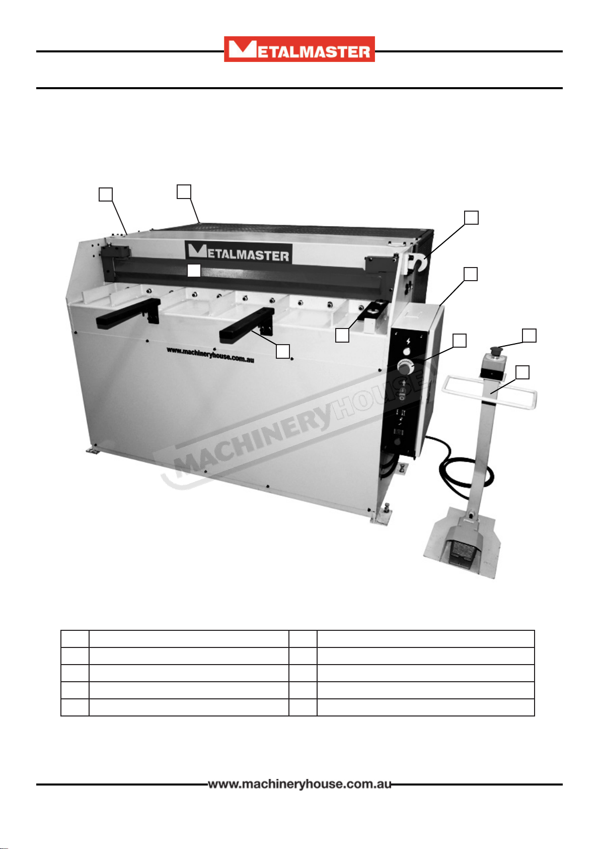
1.3 IDENTIFICATION
A
AMain Frame FMobile Foot Control
BRear Guard GSquaring Arm
CLifting Hook HSheet Supports
DControl & Electrical Box IFinger Guard
EEmergency Stops
B
C
D
E
F
G
H
I
E
22/07/2019
Instructions Manual for SG-420 (S535)
5
6
OPERATION MANUAL
DO NOT use this machine unless you have read this manual or have been instructed in the use
of this machine in its safe use and operation
This manual provides safety instructions on the proper setup, operation, maintenance, and
service of this machine. Save this manual, refer to it often, and use it to instruct other operators.
Failure to read, understand and follow the instructions in this manual may result in re or
serious personal injury—including amputation, electrocution, or death.
The owner of this machine is solely responsible for its safe use. This responsibility includes, but
is not limited to proper installation in a safe environment, personnel training and authorization
to use, proper inspection and maintenance, manual availability and comprehension, of the
application of the safety devices, integrity, and the use of personal protective equipment.
The manufacturer will not be held liable for injury or property damage from negligence,
improper training, machine modications or misuse.
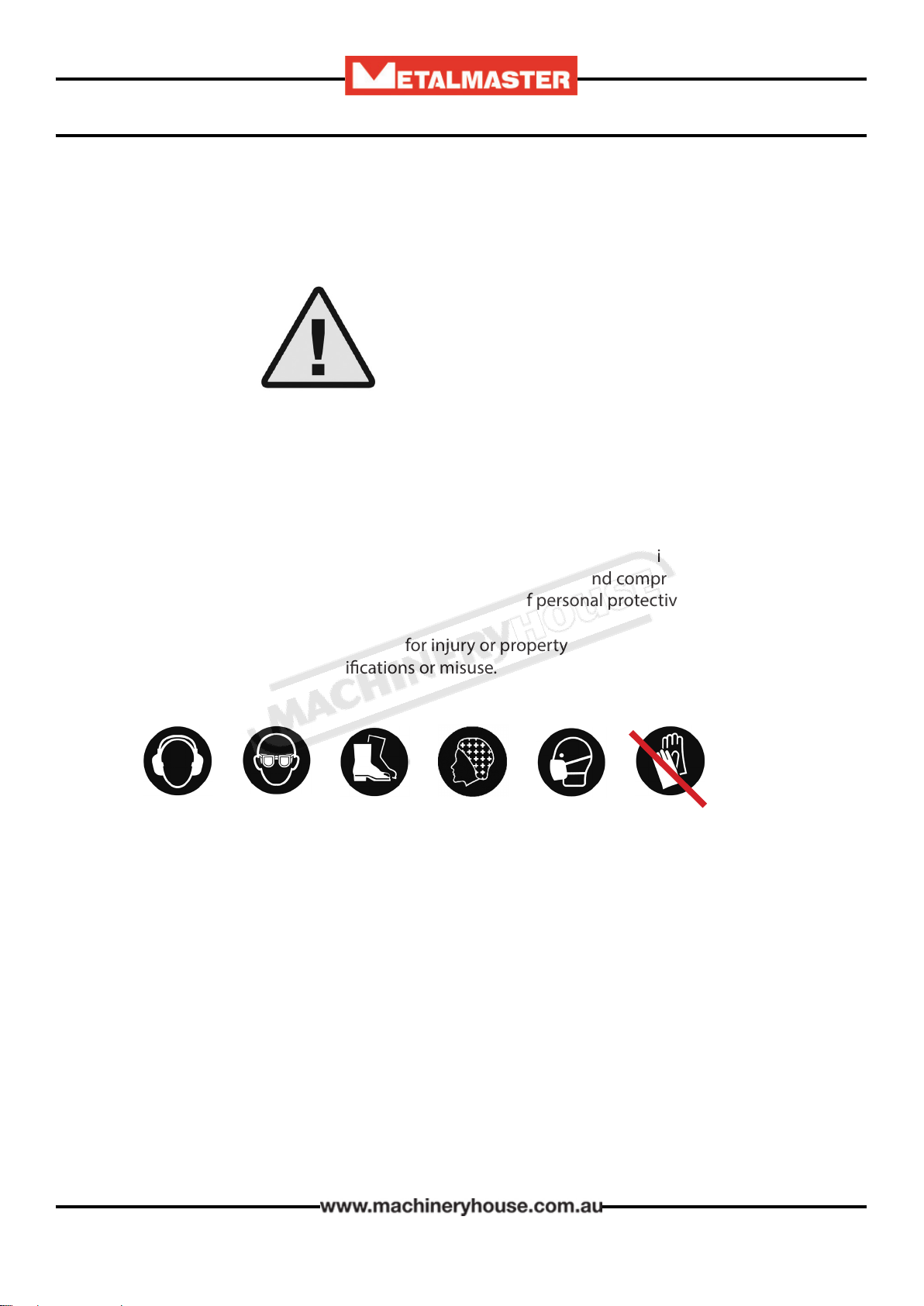
WARNING
2.1 GENERAL METALWORKING MACHINE SAFE PRACTICES
Always wear safety glasses or goggles.
Wear appropriate safety footwear.
Wear respiratory protection where required.
Gloves should never be worn while operating the machine, and only worn when
handling the work-piece.
Wear hearing protection in areas > 85 dBA. If you have trouble hearing someone speak
from one metre (three feet) away, the noise level from the machine may be hazardous.
DISCONNECT THE MACHINE FROM POWER when making adjustments or servicing.
Check and adjust all safety devices before each job.
Ensure that guards are in position and in good working condition before operating.
Ensure that all stationary equipment is anchored securely to the oor.
Ensure all machines have a start/stop button within easy reach of the operator.
Each machine should have only one operator at a time. However, everyone should know
how to stop the machine in an emergency.
22/07/2019
Instructions Manual for SG-420 (S535)
6

7
OPERATION MANUAL
Ensure that keys and adjusting wrenches have been removed from the machine before
turning on the power. Appropriate storage for tooling should be provided.
Ensure that all cutting tools and blades are clean and sharp. They should be able to cut freely
without being forced.
Stop the machine before measuring, cleaning or making any adjustments.
Wait until the machine has stopped running to clear cuttings with a vacuum, brush or rake.
Keep hands away from the cutting head and all moving parts.
Avoid awkward operations and hand positions. A sudden slip could cause the hand to move
into the cutting tool or blade.
Return all portable tooling to their proper storage place after use.
Clean all tools after use.
Keep work area clean. Floors should be level and have a non-slip surface.
Use good lighting so that the work piece, cutting blades, and machine controls can be seen
clearly. Position any shade lighting sources so that they do not cause any glare or reections.
Ensure there is enough room around the machine to do the job safely.
Obtain rst aid immediately for all injuries.
Understand that the health and re hazards can vary from material to material. Make sure all
appropriate precautions are taken.
Clean machines and the surrounding area when the operation is nished.
Use proper lock out procedures when servicing or cleaning the machines or power tools.
DO NOT
×Do not distract an operator. Horseplay can lead to injuries and should be strictly prohibited.
×Do not wear loose clothing, gloves, necktie’s, rings, bracelets or other jewellery that can be
come entangled in moving parts. Conne long hair.
×Do not handle cuttings by hand because they are very sharp. Do not free a stalled cutter
without turning the power o rst. Do not clean hands with cutting uids.
×Do not use rags or wear gloves near moving parts of machines.
×Do not use compressed air to blow debris from machines or to clean dirt from clothes.
×Do not force the machine. It will do the job safer and better at the rate for which it was
designed.
2.1 GENERAL METALWORKING MACHINE SAFE PRACTICES Cont.
BEFORE OPERATING ANY MACHINE, TAKE TIME TO READ
AND UNDERSTAND ALL SAFETY SIGNS AND SYMBOLS.
IF NOT UNDERSTOOD SEEK EXPLANATION FROM YOUR
SUPERVISOR.
22/07/2019
Instructions Manual for SG-420 (S535)
7

8
OPERATION MANUAL
2.2 SAFE WORK PROCEDURE METAL CUTTING GUILLOTINE
DO NOT use this machine unless you have been instructed in its safe use and
operation and have read and understood this manual
Safety glasses must be
worn at all times in work
areas
Long and loose hair must
be contained.
Gloves must not be
worn when using this
machine.
Sturdy footwear must be
worn at all times in work
areas
Close tting/protective
clothing must be worn
Rings and jewelery must
not be worn.
PRE-OPERATIONAL SAFETY CHECKS
Locate and ensure you are familiar with all machine operations and controls.
Ensure all guards are tted, secure and functional. Do not operate if guards are missing or
faulty.
Check workspaces and walkways to ensure no slip/trip hazards are present.
Ensure working parts are well lubricated and free of rust and dirt.
Ensure the area around the machine is adequately lit.
Be aware of other people in the area. Ensure the area is clear before using equipment.
Ensure cutting table is clear of scrap and tools.
OPERATIONAL SAFETY CHECKS
Only one person may operate this machine at any one time.
Use correct lifting procedures when handling large sheets of material.
Take care during the initial feeding of the workpiece into the machine.
The workpiece should always be held suciently far back from the edge being fed into the
guillotine.
Ensure ngers and limbs are clear before operating the guillotine.
Hold material rmly to prevent inaccurate cutting due to creep.
When cutting, ensure your feet are positioned to avoid unintentional contact with the foot
operated lever.
HOUSEKEEPING
Place all o-cuts in the storage rack or waste bin.
Leave the work area in a safe, clean and tidy state.
DON’T
Do not faulty equipment. Immediately report suspect machinery.
Never attempt to cut rod, strap or wire.
Do not attempt to cut material beyond the capacity of the machine.
POTENTIAL HAZARDS
qSharp edges and burrs. qCrush and pinch points. qManual handling injuries
22/07/2019
Instructions Manual for SG-420 (S535)
8

9
OPERATION MANUAL
2.3 LIFTING INSTRUCTIONS
On the day that the machine arrives, make sure that a crane with sucient capacity is available
to unload the machine from the vehicle. Ensure access to the chosen site is clear and that doors
and ceilings are suciently high and wide enough to receive the machine.
To handle the machine, the slings should be positioned so the machine is level when lifted.
When using slings please take note of the sling angle and the loads that apply
When the slings are at a 45° angle then each sling is
carrying the equivalent of 50% of load weight. (Fig.2.1).
When the slings are at a 90° angle then each sling will
have a weight equal to 75% of the load on each sling.
(Fig 2.2)
Note! The manufacturer recommends not to exceed 90°
angle
Fig 2.2
Fig 2.1.
The machine is supplied with lifting points that are
designed to lift the machine safely. (Fig.2.3)
When lifting the machine only certied lifting slings
should be used.
Make sure that when lifting, the machine is level and
will not tip over.
Check that the lifting slings do not interfere with the
hydraulic pipes or electrical conduits.
Failure to follow these instructions could cause damage
to the machine
NOTE: Only people with rigging qualications should
be used to direct the lifting of this machine.
Lifting Points
Fig. 2.3
To avoid injury or death, keep all parts of the crane, the rigging and parts of the machine, at
least 6 meters away from all overhead electrical power lines and equipment.
ELECTROCUTION HAZARD
22/07/2019
Instructions Manual for SG-420 (S535)
9
10
OPERATION MANUAL
The unpainted surfaces of the machine have been coated with a waxy oil to protect them from
corrosion during shipment. Remove the protective coating with a solvent cleaner or a citrus
based degreaser.
Optimum performance from your machine will be achieved when you clean all moving parts or
sliding contact surfaces that are coated with rust prevented products.
Hafco advise to avoid chlorine based solvents, such as acetone or brake parts cleaner, as they
will damage painted surfaces and strip metal should they come in contact. Always follow the
manufacturer’s instructions when using any type of cleaning product.
CLEAN - UP
3. SETUP
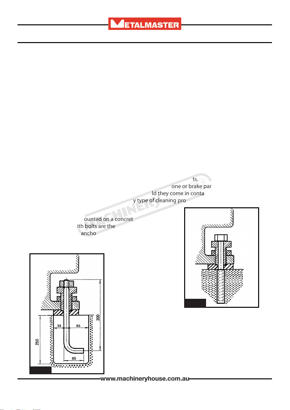
OPTIONS FOR MOUNTING
The machine is best mounted on a concrete slab.
Masonry anchors with bolts are the best way to anchor ma-
chinery, because the anchors sit ush with the oor surface,
making it easy to unbolt and move the machine later, if
needed. (Fig. 3-1)
3.1 SITE PREPARATION AND INSTALLATION
In some case a suitable foundation may not be available
and a new one may need to be prepared.
The foundation should be concrete approximately 200mm
thick with pockets left clear for the hold down bolts. The
hold down bolts can be “L” shape as per the example in
Fig. 3-2
Fig.3-2
Fig. 3-1
When selecting the site for the machine, consider the largest size of workpiece that will be
processed through the machine and provide enough space around the machine for operat-
ing the machine safely. Consideration should be given to the installation of auxiliary equip-
ment. Leave enough space around the machine to open or remove doors/covers as required
for the maintenance and service as described in this manual.
It is recommended that the machine is anchored to the oor to prevent tipping or shifting. It
also reduces vibration that may occur during operation. The machine should be mounted on
a reinforced concrete oor with a minimum of 150mm thickness. The oor must be able to
support the weight of the machine and any workpiece that is to be worked.
22/07/2019
Instructions Manual for SG-420 (S535)
10
11
OPERATION MANUAL
3.2 MACHINE LEVELING
To set your machine up so that it operates to optimum performance, apply the following level-
ing procedure
After your guillotine has been anchored to a concrete slab oor, it then needs to be leveled. The
leveling is performed using the screws on each pad.(Fig. 3.1). Loosen the hold down bolts and
place a level on the surface of the working table. Tolerances: 1000:0.30mm, for both longitudi-
nal and transverse.
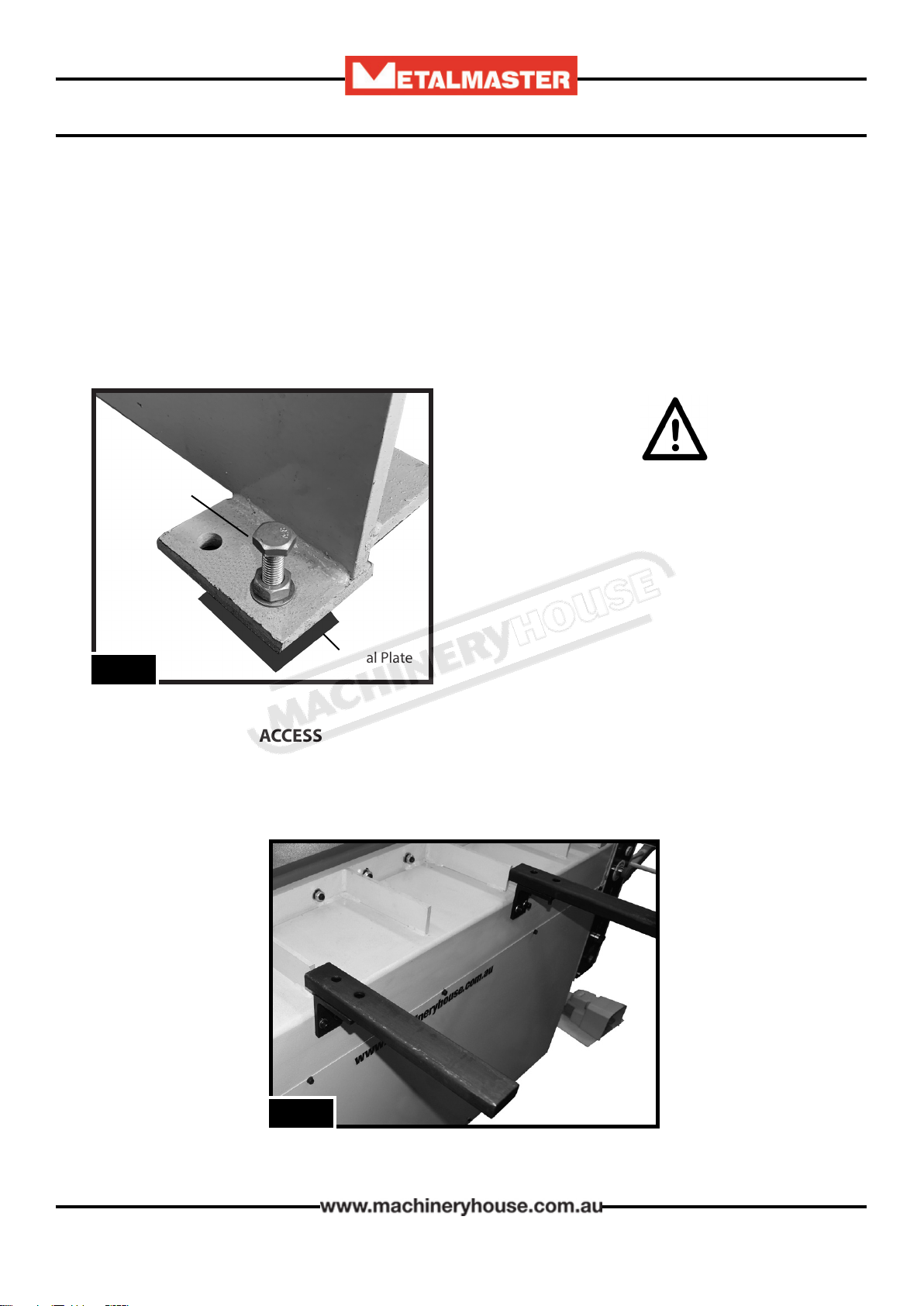
Metal plates need to be placed under each jacking screw to distribute the load. Once level then
tighten the hold down bolts.
The machine must not rest on supports
other than those dened in Fig. 3.1
qBolt the support arms onto the feed table. Ensure they are level and square to the table.
(Fig.3.2)
Fig.3.2
3.3 ATTACHING THE ACCESSORIES.
Fig.3.1
Jacking Screw
Metal Plate
22/07/2019
Instructions Manual for SG-420 (S535)
11
12
OPERATION MANUAL
qPlace the squaring stop Fig 3.3 into position
on the table top, securing into place with the
bolts supplied. Check that the square stop is
square to the blade.
Adjustment can be made by loosening the
bolts and moving the stop by the amount
allowed by the clearance of the holes.
qRe tighten the screws.
Fig. 3.3
3.3 ATTACHING THE ACCESSORIES Cont.
Fig. 3.4 Fig. 3.5
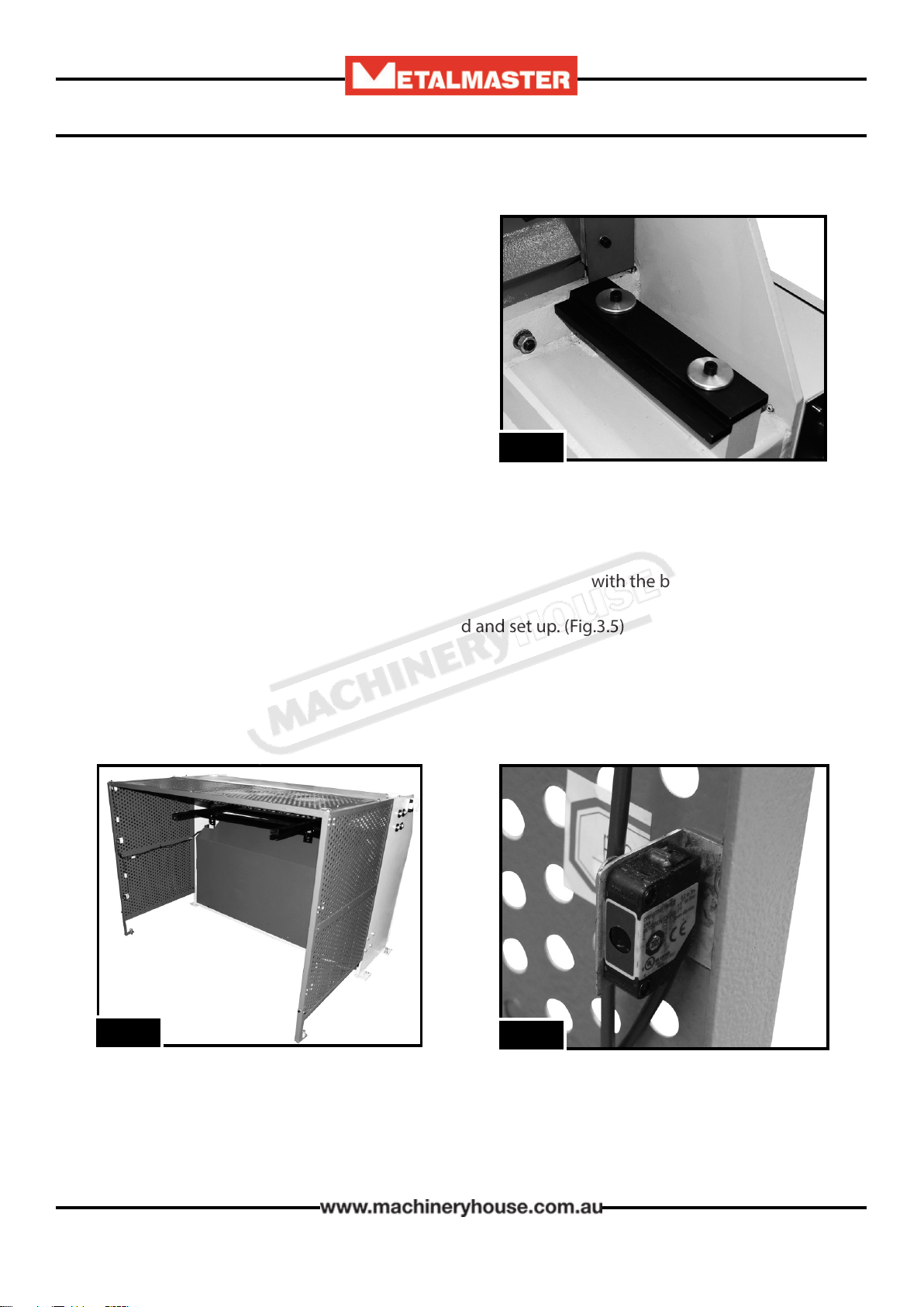
ATTACHING THE REAR SAFETY FENCE
qUnpack and attach the rear fence to the back of the machine with the bolts supplied.
(Fig.3.4)
qEnsure that the sensors have been connected and set up. (Fig.3.5) (See “4.2 Safety Sensor
Alignment” on Page 15)
22/07/2019
Instructions Manual for SG-420 (S535)
12
13
OPERATION MANUAL
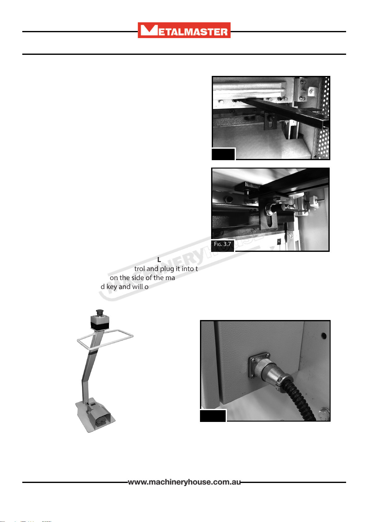
MANUAL BACK GAUGE
Consists of two arms similar to the front stops. These
are positioned on the underside of the top beam.
Adjustment for being level and parallel can be made
as for the front stops. Once the arms have been posi-
tioned, slide the “slide blocks” onto the arms and bolt
the back gauge to the blocks. (Fig.3.6, 7)
NOTE: Ensure that the brass slug is under the bolt
clamp to avoid damage to the arm.
qTo adjust the back gauge, undo the clamp and
slide the back gauge to the required setting and
re-tighten the clamp.
Fig. 3.6
Fig. 3.8
ATTACHING THE MOBILE FOOT PEDAL
qUnpack the mobile foot control and plug it into the socket provided on the back of the
control box located on the side of the machine. (Fig.3.8) The plug and socket are tted with
a location slot and key and will only connect in the one position
Fig. 3.7
22/07/2019
Instructions Manual for SG-420 (S535)
13

14
OPERATION MANUAL
The full-load current rating is the amperage a machine draws when running at 100% of the out-
put power. Where machines have more than one motor, the full load current is the
amperage drawn by the largest motor or a total of all the motors and electrical devices that
might operate at one time during normal operations.
Full-Load Current Rating for these machine at 240V is 12.8 Amps
It should be noted that the full-load current is not the maximum amount of amps that the
machine will draw. If the machine is overloaded, it will draw additional amps beyond the
full-load rating and if the machine is overloaded for a long period of time, damage, overheating,
or re may be caused to the motor and circuitry.
This is especially true if connected to an undersized circuit or a long extension lead. To reduce
the risk of these hazards, avoid overloading the machine during operation and make
sure it is connected to a power supply circuit that meets the requirements.
3.5 FULL-LOAD CURRENT RATING
Place the machine near an existing power source. Make sure all power cords are protected from
trac, material handling, moisture, chemicals, or other hazards. Make sure there is access to a
means of disconnecting the power source. The electrical circuit must meet the requirements for
240V. To minimize the risk of electrocution, re, or equipment damage, these machines should
be hard wired with installation work and electrical wiring done by a qualied electrician.
NOTE : The use of an extension cord is not recommended as it may decrease the life of electrical
components on your machine.
3.4 ELECTRICAL INSTALLATION
ELECTRICAL REQUIREMENTS
Nominal Voltage.........................................240V
Cycle............................................................50 Hz
Phase...............................................Single Phase
Power Supply Circuit............................15 Amps
Full Load Current...............................12.8 Amps
(Full load current rating is also on the specication plate on the motor.)
22/07/2019
Instructions Manual for SG-420 (S535)
14
15
OPERATION MANUAL
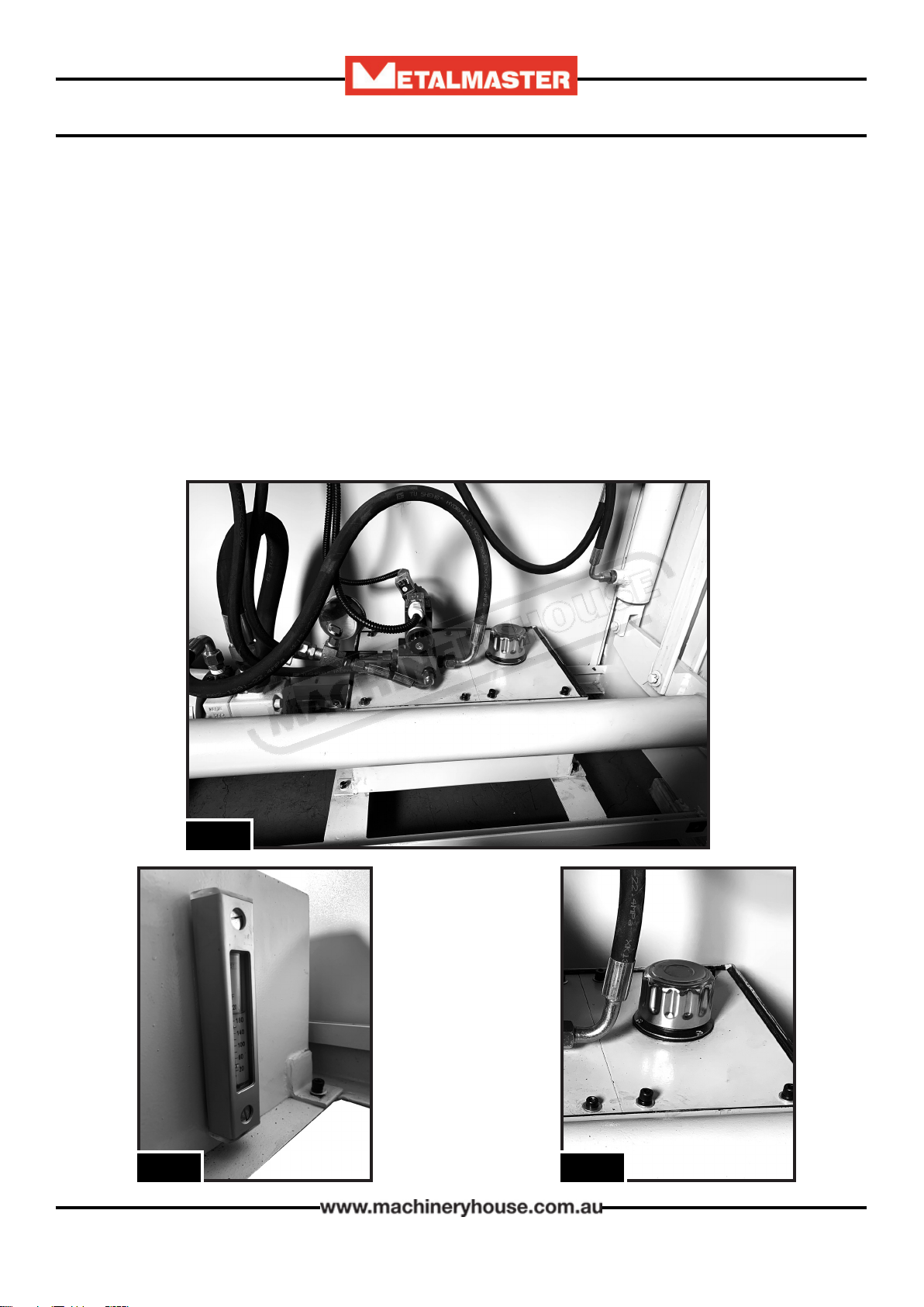
3.5 FILLING THE HYDRAULIC OIL TANK.
The machine is shipped with the oil tank empty for safety. Before the machine is used the oil
tank needs to be lled.
When lling the tank with oil, make sure that the top of the tank is clean and free from dust and
dirt.
qRemove the rear guard to access the oil tank (Fig 3.9)
qRemove the screws from the oil tank cover and remove the cover
qUsing a clean cloth wipe out the bottom of the tank making sure there is no dirt or dust
remaining in the tank.
qReplace the oil tank cover and open the oil cap.(Fig 3.11)
qUsing a pump or proper equipment, add 46 grade hydraulic oil into the tank
qOil level must be lled to the middle mark of the oil indicator. (Fig. 3.10)
qAlways keep the oil at the same level.
Fig.3.9
Fig.3.10 Fig.3.11
22/07/2019
Instructions Manual for SG-420 (S535)
15

16
OPERATION MANUAL
4. COMMISSIONING
4.1. PREPARATION OF THE MACHINE
qRemove all wrapping and packing grease from the machine.
qCheck the machine for loose bolts. Tighten as required.
qInspect for oil leakage or loose ttings. Similarly check the main rams between the frames.
qClean the blades and tighten the securing bolts as required. Examine the cutting edges of
both blades for damage.
qInform your service provider of any damage or faults with the machine.
Warning- Follow all setup instructions before starting the
hydraulic pump.
The safety circuit consists of a reset button and two rear side
guards, each having 3 sensors. The machine has a RED warning
light mounted on the control panel when the circuit has been
tripped.. (Fig.4.1) When the main power is switched on or the
rear sensors have been tripped, the safety circuit must be reset
before the hydraulic pump can be started.
Fig. 4.1
Reset Button
The reset button is mounted on the rear of the control panel
under the isolating switch. Press to reset the safety circuit
(Fig.4.2)
4.2 SAFETY SENSOR ALIGNMENT
Fig. 4.2
22/07/2019
Instructions Manual for SG-420 (S535)
16

17
OPERATION MANUAL
Machine setup- First ensure that the machine is level and all four levelling jacking bolts are
correctly adjusted. Ensure the rear fences are tight and the stabilizing bolt is on the ground to
stop the fence moving around.
Alignment- The sensors are sensitive to alignment so try to align as accurately as possible. If
the sender is only slightly aligned with the receiver any vibration when cutting will stop the
pump and the safety circuit will have to be reset again. Alignment could involve loosening the
sensor mounting screws or bending the mounting brackets to get the best alignment
Identifying sensors
Senders- Each sender has a red light on top of the unit
and a red light on the front. These two lights will be on
all the time while the machine has power.
4.2 SAFETY SENSOR ALIGNMENT CONT.
22/07/2019
Instructions Manual for SG-420 (S535)
17

18
OPERATION MANUAL
4.2 SAFETY SENSOR ALIGNMENT. CONT.
Receivers- Each receiver has two lights on top of the unit. These lights indicate if the receiver
has power and if it has been aligned correctly with the sender.
No Lights on Green light on Orange and green light on
No power Power on but not aligned Has Power & aligned ok
Alignment order- The receivers are wired in series and must be aligned in the correct order. As
each receiver is aligned correctly it will send power to the next receiver.
No-1 receiver (middle)- A green light on indicates it has power. When it is correctly aligned
with the sender an orange & green light will be on and it will send power to No-2 receiver.
No-2 receiver (top)- A green light on indicates it has power. When correctly aligned with the
sender an orange & green light will be on and it will send power to the No-3 receiver.
No-3 receiver (bottom)- will have a green light on and when it is correctly aligned with the
sender the orange & green light will be on and it will send power to the reset button.
Successful alignment- When all 3 receivers are aligned correctly with their corresponding
senders, they should all have an orange and green light on top. The reset button can now be
pressed.
22/07/2019
Instructions Manual for SG-420 (S535)
18

19
OPERATION MANUAL
4.3 CONTROLS
Before operating the machine it is important to know where the
controls are and what each item does.
The controls for the machine are found in three places.
1. The back of the electrical cabinet
2. The control panel situated on the right hand side of the machine
on the front of the electrical cabinet.
3. The mobile foot pedal.
Below are the explanation of each control.
A. Isolating Switch. Main power supply switch mounted on the
back of the electrical cabinet. (Fig.4.4)
B. Safety Reset Button. This button resets the safety circuit after
the rear safety beam has been broken. (Fig.4.4)
C. Power Lamp. This light is illuminated when the power supply is
switched on. (Fig.4.5)
D. Emergency Stop Buttons (2). When pressed disconnects the
power to the machine. The button needs to be twisted to release
and reset the circuity (Fig.4.5) (Fig.4.6)
E. ON/OFF Button. Switches the Hydraulic pump ON of OFF (Fig.4.5)
F. Function Switch. This switch switches the function between
“INCH” or “CYCLE” mode (Fig.4.5)
G. Rear Sensor Lamp. Is illuminated when the rear safety guard
circuit has been tripped (Fig.4.5)
D
E
F
G
A
B
C
H
D
H. Operating Pedal. When pressed, activates
the guillotine when either “Inching” or
Cycling” mode has been selected. (Fig.4.6)
If in the “INCHING” mode, the top blade can
be moved and stopped by pressing and
releasing the pedal.
If in the “CYCLING” mode, pressing the pedal
will complete one full cycle.
Fig. 4.6
Fig.4.4
Fig. 4.5
22/07/2019
Instructions Manual for SG-420 (S535)
19

20
OPERATION MANUAL
4.4 COMMISSIONING CHECK LIST.
Before starting the machine the following checks must be carried out.
qInstallation and machine preparation has been performed according to the instructions in
this manual.
qFill the oil reservoir with 46 grade hydraulic oil and ensure that the oil filter breather cap is
fitted
qAll grease nipple points have been lubricated.
qElectrical earth fitted and power circuits, switches, and foot-pedal have been checked.
qCheck power connections and any damage to any wiring.
qSetup rear sensors
qTest safety operation, Emergency stop, rear sensors, stop button etc.
qTest cut material and check quality of cut
qTools, equipment and personnel are clear of the machine.
qOperation Manual on how to operate the machine has been read.
5. OPERATION INSTRUCTIONS
5.1 PRE-OPERATIONAL SAFETY CHECK PRIOR TO OPERATING
Before operating the machine the rear safety beam guard
needs to be checked.
Below are the steps that need to be followed.
1. Start the machine as per the instruction procedures
2. Stand outside the rear safety gate & obstruct sensor (1)
3. Ensure the machine has stopped and is disabled
4. Check your control panel warning light is illuminated.
(Fig. 5.1)
5. Press the green reset button on the rear of the electrical box
(Fig. 5.2)
6. Press the Hydraulic pump start button on the control panel
to activate the operational system. (Fig. 5.3)
7. Repeat steps 1 to 6 for each sensor (2) & (3)
Fig. 5.1
Fig. 5.2
Fig. 5.3
22/07/2019
Instructions Manual for SG-420 (S535)
20
This manual suits for next models
1
Table of contents
Other MetalMaster Cutter manuals


