Metasys META Air 24 Installation instructions

Kompressoren
META Air |META CAM
Gerätedokument
Einbau, Betrieb und Wartung
Compressors
META Air |META CAM
Equipment Logbook
Assembly, operation and maintenance
Compresseurs
META Air |META CAM
Livret d’appareil
Installation, fonctionnement et entretien
Compressori
META Air |META CAM
Verbale d’installazione
Montaggio, funzionamento e manutenzione
META
AIR |CAM
EN

EN
2
3. General information
The safety, reliability and performance of the appliance is
only guaranteed by METASYS if the following instructions are
observed:
Assembly, alterations or repairs may exclusively be carried out
by authorized service personnel in compliance with EN Standard
60601-1 (International Standard for Medical Electrical Apparatus, in
particular Part 1: General Rules for Safety).
The electrical installation must comply with the regulations of the IEC
(International Commission for Electrical Engineering).
The apparatus must exclusively be used in conformity with the
instructions for installation, operation and maintenance.
Only original parts may be used for repairs or replacements.
After commissioning, complete the proof of installation at the front
page of this manual and send this to METASYS in order to de ne the
warranty period.
All inspection and service work must be entered into the device
documentation at the rst pages of this manual
When requested by an authorized engineer, METASYS agrees to make
all documents available for the use of technically quali ed service
personnel.
METASYSaccepts noresponsibilityfor damages caused dueto external
factors, such as wrong installation, improper use of the apparatus or
unauthorized technical intervention.
Users must study equipment and assure themselves of its good
condition before every use.
When the complete compressor is dismantled at the end of its service
life, it must be returned to the manufacturer for orderly disposal.
1. Index
The header on each page defines the user group particular information is
aimed at.
Chapter Page
1. Index 2
2. Key to symbols 2
3. General Information 2
4. Use 3
5. Scope of delivery 3
6. Explanation of the type plate 3
7. Technical data 4
8. Functional description of the compressor 8
9. Functional description of the membrane dryer 8
10. Storage and transportation conditions 9
11. Installation guidelines 9
12. Instrument unit 10
13. Electrical connections 10
14. Preparations before rst use 11
15. Commissioning and usage 13
16. Wiring diagrams 14
17. Guarantee, service and maintenance 17
18. Decommissioning and disposal 18
19. Troubleshooting 19
2. Explanation of the pictograms
iInformation
Caution!
General warning sign
Follow instructions for use
Index Explanation of the pictograms General information
Practice personnel, technicians

1
2
3
3.1
3.3
3.5 3.63.4
3.2
3
EN
Use Scope of delivery Explanation of the type plate
Practice personnel, technicians
4. Use - intended purpose
METASYS META Air / META CAM compressors produce compressed air for
the dental treatment of patients, which complies with the high dental
standard requirements for air pressure, air ow rate, humidity, oil content
and particle contamination.
Picture 1 : META Air 150
Picture 2 : META Air 150 Light
The compressors are designed for operation in dry ventila-
ted rooms and may therefore not be operated in a damp or
wet environment.
Use of the compressors in the vicinity of gases or inamma-
ble liquids is also prohibited.
5. Scope of delivery
All META Air / META CAM compressors are shipped in a single
package consisting of a pallet plus carton. A booklet containing the
installation proof, equipment logbook and manual for installation,
operation and maintenance is included in each shipment.
6. Explanation of the type plate
Picture 3 : The type plate is located on the tting panel.
3.1 Equipment type
3.2 Mains supply data
3.3 Serial number
3.4 Address of the manufacturer
3.5 CE marking
3.6 Protection Class I

4
5
6
7
EN
4
Technical data
Practice personnel, technicians
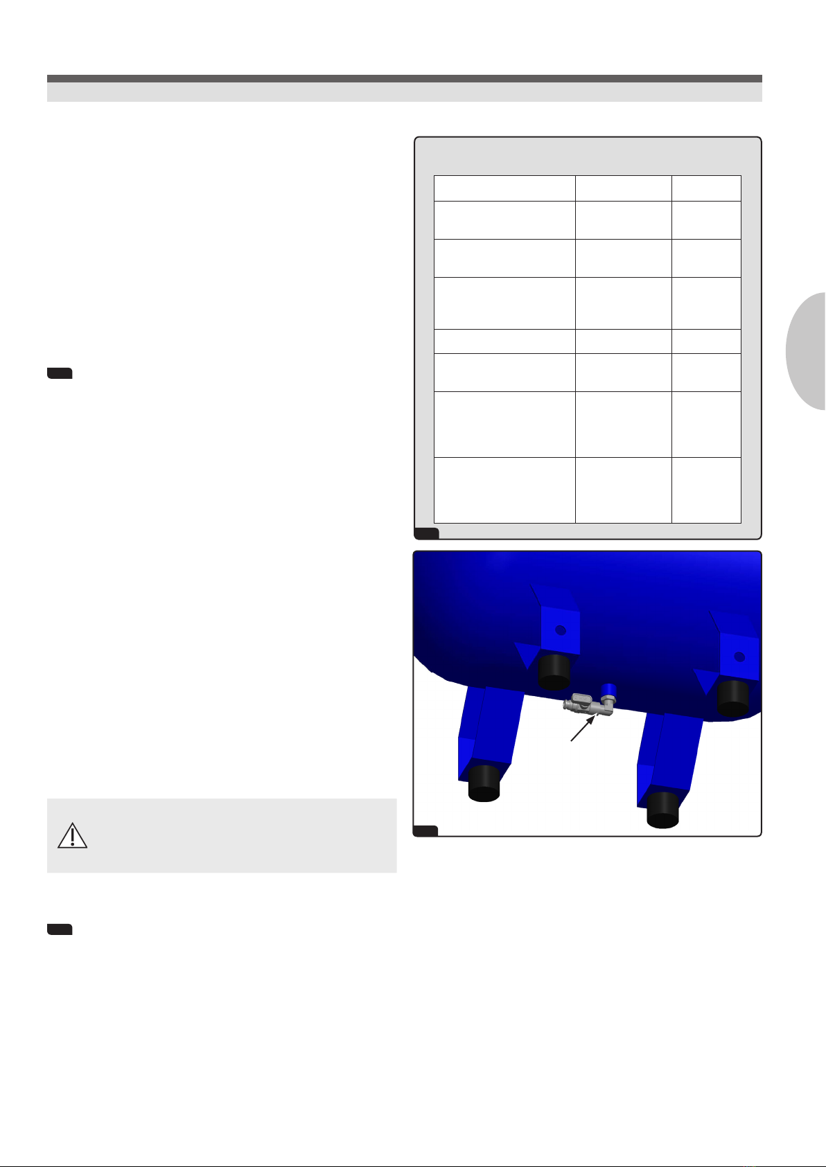
7. Technical data
4 META Air 24
Tank capacity 24 l
Electric motor power 1,1 kW
Delivery rate 135 l/min
Dimensions (H x W x D) 600 x 430 x 400 mm
Power supply 230 V
Frequency* 50 Hz
Pressure range 5 -7 bar
Sound level 65 dB(A)
2 META Air 24 Light META Air 24s Light
Tank capacity 24 l 24 l
Electric motor power 1,1 kW 0,55 kW
Delivery rate 135 l/min 135 l/min
Dimensions (H x W x D) 600x430 x400 mm 550x400x400 mm
Power supply 230 V 230 V
Frequency* 50 Hz 50 Hz
Pressure range 5 -7 bar 5 -7 bar
Sound level 65 dB(A) 65 dB(A)
6 META Air 30
Tank capacity 40 l
Electric motor power 1,1 kW
Delivery rate 120 l/min
Dimensions (H x W x D) 770 x 710 x 410 mm
Power supply 230 V
Frequency* 50 Hz
Pressure range 5 -7 bar
Sound level 64 dB(A)
7 META Air 30 Light
Tank capacity 40 l
Electric motor power 1,1 kW
Delivery rate 135 l/min
Dimensions (H x W x D) 770 x 600 x 410 mm
Power supply 230 V
Frequency* 50 Hz
Pressure range 5 -7 bar
Sound level 64 dB(A)
* also available with 60 Hz

1
2
3
4
5
EN
Technical data
Practice personnel, technicians
7. Technical data
1 META Air 150 META CAM 150
Tank capacity 40 l 40 l
Electric motor power 1,5 kW 1,5 kW
Delivery rate 152 l/min 152 l/min
Dimensions (H x W x D) 770 x 710 x 410mm 770 x 710 x 410mm
Power supply 230 V 230 V
Frequency* 50 Hz 50 Hz
Pressure range 5-7 bar 8-10 bar
Sound level 66 dB(A) 66 dB(A)
2 META Air 250 META CAM 250
Tank capacity 40 l 40 l
Electric motor power 2,2 kW 2,2 kW
Delivery rate 225 l/min 225 l/min
Dimensions (H x W x D) 810 x 710 x 410mm 810 x 710 x 410mm
Power supply 230 V 230 V
Frequency* 50 Hz 50 Hz
Pressure range 5-7 bar 8-10 bar
Sound level 66 dB(A) 66 dB(A)
3 META Air 450 META CAM 450
Tank capacity 90 l 90 l
Electric motor power 4,4 kW 4,4 kW
Delivery rate 450 l/min 450 l/min
Dimensions (H x W x D) 820x1100x630 mm 820x1100x630 mm
Power supply 400 V 400 V
Frequency* 50 Hz 50 Hz
Pressure range 5-7 bar 8-10 bar
Sound level 68 dB(A) 6970 dB(A)
4 META Air 650 META CAM 650
Tank capacity 200 l 200 l
Electric motor power 6,6 kW 6,6 kW
Delivery rate 660 l/min 660 l/min
Dimensions (H x W x D) 900x1450x820 mm 900x1450x820 mm
Power supply 400 V 400 V
Frequency* 50 Hz 50 Hz
Pressure range 5-7 bar 8-10 bar
Sound level 72 dB(A) 72 dB(A)
* also available with 60 Hz

5
6
7
8
EN
6
Technical data
Practice personnel, technicians
7. Technical data
5 META Air 150 Light
Tank capacity 40 l
Electric motor power 1,5 kW
Delivery rate 170 l/min
Dimensions (H x W x D) 770 x 600 x 410 mm
Power supply 230 V
Frequency* 50 Hz
Pressure range 5-7 bar
Sound level 66 dB(A)
6 META Air 250 Light
Tank capacity 40 l
Electric motor power 2,2 kW
Delivery rate 250 l/min
Dimensions (H x W x D) 810 x 600 x 410 mm
Power supply 230 V
Frequency* 50 Hz
Pressure range 5-7 bar
Sound level 66 dB(A)
7 META Air 450 Light
Tank capacity 90 l
Electric motor power 4,4 kW
Delivery rate 500 l/min
Dimensions (H x W x D) 820 x 1100 x 600 mm
Power supply 400 V
Frequency* 50 Hz
Pressure range 5-7 bar
Sound level 68 dB(A)
8 META Air 650 Light
Tank capacity 90 l
Electric motor power 4,4 kW
Delivery rate 500 l/min
Dimensions (H x W x D) 820 x 1100 x 600 mm
Power supply 400 V
Frequency* 50 Hz
Pressure range 5-7 bar
Sound level 69 dB(A)
* also available with 60 Hz

1
2
3
7
EN
Technical data
Practice personnel, technicians
7. Technical data
1 META Air 900
Tank capacity 270 l
Electric motor power 11 kW
Delivery rate 780 l/min
Dimensions (H x W x D) 1030 x 1560 x 1000 mm
Power supply 400 V
Frequency* 50 Hz
Pressure range 5 - 7 bar
Sound level 75 dB(A)
2 META Air 900 Light
Tank capacity 270 l
Electric motor power 11 kW
Delivery rate 900 l/min
Dimensions (H x W x D) 1030 x 1560 x 1000 mm
Power supply 400 V
Frequency* 50 Hz
Pressure range 5 - 7 bar
Sound level 75 dB(A)
3 META Air 1300 Light
Tank capacity 500 l
Electric motor power 16,3 kW
Delivery rate 1350 l/min
Dimensions (H x W x D) 1050 x 1980 x 780 mm
Power supply 400 V
Frequency* 50 Hz
Pressure range 5 - 7 bar
Sound level 78 dB(A)
Operating time
META Air:
An operating time of 70% is possible at the specied delivery rate.
META Air Light:
An operating time of 80 % is possible at the specied delivery rate.
META CAM:
An operating time of ˂ 50% is possible at the specied delivery rate.

2
1
8
7
6
9
3
2
1
10
5
4
EN
8
8. Functional description of the compressor
See picture 1
Compressors without a membrane dryer (Light models):
The compressor power unit sucks in air from the outside through the
air intake lter 1. The air is compressed in an oil-free compression
chamber 2, then passes through a delivery hose 3and is forced
through the non-return valve 4into the pressure tank 5. The air
ow is regulated by a valve plate that allows air ow in one direction only.
Compressors with a membrane dryer:
The compressor power unit sucks in air through the air intake lter 1.
The air is compressed in an oil-free compression chamber 2, then is
forced through the cooler 6which cools down the compressed air and
thus forms condensate water.
The condensate is trapped by a 5 mµ lter 7located below the cooler.
A second 0,01 mµ lter 8blocks further water droplets to ensure high
quality, clean air. This double ltration system has a semi-automatic
drain system that empties the small lters receivers everytime pressure
is discharged.
The clean compressed air then passes through the membrane dryer 9
where residual humidity is removed and the compressed air reaches an
average dew point value of -35°C. Dry, compressed air is delivered to
the air receiver through a hose that connects the dryer to the non-return
valve 5.
The entire system is controlled by the pressure switch 10 that regulates
the ON/OFF mode of the unit. Every time the compressors reaches the cut
out pressure, it switches off and residual compressed air in the delivery
pipe system is vented out by a solenoid valve (for compressors without air
dryer) or by the membrane dryer 9- for compressors with air dryer.
9. Functional description of the membrane dryer
See picture 2
Filtered air enters the membrane dryer and water droplets are collected
on the membrane bres. While the dried air is delivered to the receiver,
a small amount of this dried air is purged back through the membrane to
sweep away the water droplets around the bers. The moisture is then
delivered to the outside through the rinsing nozzles of the membrane
dryer. Since this purge cycle is continuous, the membrane dryer can
operate without interruptions or efciency reduction.
Membrane dryers do not require any maintenance because there is no
water adsorption or adsorbing material.
Periodical maintenance needs to be performed on the double ltration
system (0,5 µm, 0,01 µm) before the membrane dryer. Filter cartridges
must be replaced once a year. Maintenance kits are available at METASYS.
Functional description: Compressor Membrane dryer
Practice personnel, technicians

3
4
9
EN
10. Storage and transportation conditions
The compressor is dispatched by the manufacturer in a carton on a
non-returnable pallet to protect the appliance from damage during
transportation. Wherever possible, the original packaging should always
be used for transportation. Therefore it is advised to keep the original
packaging.
During transportation the compressor must be protected from moisture,
dirt and extreme temperatures. The packaged compressors must be stored
in a dry place to protect it from humidity (max. relative air humidity:
70%). Storage temperature must be between -10°C and +40°C.
The compressor may only be transported unpressurised.
Before it is transported, it is essential that the compressed
air from the pressure tank and pressure hoses is released
and any condensate water is drained off.
11. Installation guidelines
Unpack the compressor and check carefully to ensure that it is in perfect
condition. Assemble the support legs as supplied 3 . The compressor
may only be installed and operated in a dry, well-ventilated and low-dust
location. If there is insufcient air ow, a suction device or ventilator of
the correct dimensions must be installed. The ambient temperature must
be between +5°C and +40°C.
The motor fan ensures that the power unit is force-cooled effectively.
However, for this to happen, the air must be able to ow in and out without
obstructions. If this is not the case, a separate ventilation system must be
installed 4 .
The compressor must be installed in such a way that it is easily accessible
for operation and maintenance. The compressor must be placed on a
level oor which is sufciently robust. The compressor must not touch
any other objects due to heat development. It is not necessary to provide
a special foundation or base. The compressor may simply be placed on
a level oor. If the compressor is tted in a mounting bracket, then the
mounting bracket should not be secured to the ground. It is recommended
to attach four vibration dampers.
Storage and transportation conditions Installation guidelines
Practice personnel, technicians

1
2
3
2.3
2.2
2.4
2.1
3.1
EN
10
12. Instrument unit
The compressor is tted with an instrument unit as standard (pictures
1 and 2 . This consists of:
2.1 pressure switch
2.2 safety valve
2.3 compressed air supply
2.4 manometer
The exible delivery hose must be pushed onto a pipe connection and
secured against slippage using hose clips.
iThe exible delivery hose connecting the permanently ins-
talled compressed air pipe and the compressor prevents the
transfer of vibrations and noise.
13. Electrical connections
Connections to the mains supply may only be made by a quali ed
electrician. It must be ensured that the electrical wiring and the mains
voltage is conform with the data indicated on the type plate. A tolerance of
+/- 5% is permissible. Earthing must always be used for safety purposes.
3 The compressors must be connected to a socket which is protected
by a suitable magnetothermal switch. The socket must be easily accessible
so that the appliance can be unplugged easily from the mains supply in
the event of danger. When a compressor which is operated by three-
phase alternating current is switched on for the rst time, it is necessary
to ensure that the direction of rotation of the ventilation rotor is correct
(see arrow on housing 3.1 ).
If any electrical wires or air hoses are damaged, they must
be immediately replaced! The electrical wiring may not
touch the surfaces of the apparatus since the outer surfaces
of the compressor become hot during operation and may
thereby damage the cable insulation!
Instrument unit Electrical connections
Practice personnel, technicians

4
5
6
A
B
A
B
11
EN
14. Preparations before rst use
Before using the compressor for the rst time, it must be ensured that
all the fastenings securing the compressor for transportation have been
removed. Ensure that the compressed air lines are connected correctly.
The compressor must be connected to the mains supply in the proper
manner. Switch on the compressor at the pressure switch by rotating the
switch to position “1”.
Safety valve
The safety valve is set at 10 bar. When the compressor is ope-
rated for the rst time, the safety valve must be checked.
The safety valve may not be used to vent the pressure tank, as
this may impair the function of the safety valve.
Adjusting the pressure switch
4 / 5 / 6 The pressure switch is factory-set. If necessary,
the working pressure of the compressor may be altered at the pressure
switch.
These tasks may only be carried out by authorised technicians.
During this work the protective cover of the pressure switch
must be removed.
The adjustment can only be carried out while the unit is in use.
If problems develop with the cut-in and cut-out pressure, refer to the
following:
Screws A: Minimum pressure adjustment (cut-in) – both of them have
to be regulated at the same level. Note to regulate Max pressure, only
regulate screws A (min. pressure) because the differential pressure
is xed.
Screw B: Differential min-max pressure adjustment (cut-out) –
actually regulated at 2 bar.
The cut-in pressure is set by even adjustment of the two screws A.
Turn clockwise to increase the switch-on and anticlockwise to reduce
it.
The cut-out pressure is set by means of differential screw B (cut-in
pressure + differential = cut-out pressure). Turn clockwise to increase
the differential.
Preparations before first use
Technicians

2
1
EN
12
14. Preparations before rst use
1 Draining off condensate water
During transportation, condensate may form inside the air tank because
of temperature uctuation. Each time a compressor is installed, the
condensation water must rst be drained off – also in compressors with a
membrane dryer.
Procedure:
Check for condensate in the air receiver.
Switch off the compressor and reduce pressure to 1 bar
Place a collection container under the air receiver
Open the drain valve until there is no more condensate inside the air
receiver.
Close the drain valve again.
2 Installation of the manometer
The manometers must be installed and checked for leakage.
Preparations before rst use
Technicians

3
3
META Air Light models
META Air /CAM
models
2
1
4
13
EN
15. Commissioning and usage
See picture 3
iAutomatic start-up: If the pressure in the air receiver drops,
the compressor will switch on automatically until the maxi-
mum operational pressure is reached again.
If the maximum operational pressure is exceeded,
the compressor power unit must be switched off and
disconnected from the mains (remove the power plug.)
Inform an authorised technician.
In the event of danger, disconnect the compressor from the
mains (remove the power plug). The compressor has hot
surfaces and may cause burns upon contact.
Plug in the power cable and connect the air hose (1). Turn the pressure
switch (2) to position “1”. The compressor operates fully automatic and
is controlled by the pressure switch which stops when pressure in the tank
(3) reaches the cut out pressure, allowing compressor to start again when
it reaches the cut in pressure.
The current pressure can be read on the pressure gauge (4).
Commissioning and usage
Technicians

META Air
META Air
Light META Air
Light
META Air/
META CAM
META Air
Light
*
*
META Air
META Air/
META CAM
META Air
Light
*
*
EN
14
Wiring diagrams
Technicians
* only META Air Light versions
16. Wiring diagrams
1 META Air 24 / 24 Light / 30 / 30 Light 2 META Air 24 / 24 Light / 30 / 30 Light with cover
3 META Air 150 / 150 Light / 250 / 250 Light
META CAM 150 / 250
4 META Air 150 / 150 Light / 250 / 250 Light with cover
META CAM 150 / 250 with cover

META Air
Light
META Air Light
META Air
Light META Air/META CAM
*
META Air/
META CAM
META Air/
META CAM
*
*
15
EN
Wiring diagrams
Technicians
* only META Air Light versions
16. Wiring diagrams
Legend
F fuse
P pressure switch
M1 - M2 compressor motor 1-3
W1 - W3 ventilator 1-3
EV pressure relief valve
H hour meter
KS1 - KS3 motor contactor 1
t1 - t2 timing relay 1-2
7 META Air 450 / 450 Light / META CAM 450 - 3 phases
5 META Air 150 / 150 Light / 250 / 250 Light - 3 phases
META CAM 150 / 250 - 3 phases
6 META Air 150 / 150 Light / 250 / 250 Light with cover - 3
phases META CAM 150 / 250 with cover - 3 phases

Version with
cover
*
META Air / META CAM
META Air / META CAM
META Air Light
*
EN
16
Wiring diagrams
Practice personnel, technicians
2 META Air 650 / 650 Light / META CAM 650
* only META Air Light versions
16. Wiring diagrams
1 META Air 450 / 450 Light with cover / META CAM 450 with cover
4
17
EN
17. Guarantee, Service and maintenance
Guarantee period
The guarantee terms and conditions, which you can review in the rst
pages of this manual, apply.
Guarantee claims for compressors are valid for 12 months. If required
yearly and possible 3000 or 1500 hours maintenances are done, the
guarantee period may be extended for an additional year, however
not more than 2 years. Therefore max. possible guarantee period is 36
months.
3 Service intervals
Compulsory maintenance rates have to be met precisely. The following
maintenance and inspections have to be done: yearly lter cartridge -
exchange („Filter cartridge - exchange kit“), the 3000 or 1500 hours
maintenance, depending on compressor versions, with the „3000 hours
kit + valve block (complete)“ or the „1500 hours kit 24/30 + valve block
(complete)“. The required inspections have to be registered inside this
METASYS manual on page 11. METASYS reserves to himself the right to
request those registrations to ascertain maintenance and inspection
rates.
Repair works that go beyond the normal maintenance may only be carried
out by a qualied technician or by the METSYS Technical Customer Service.
Use only the replacement parts permitted by the manufacturer and the
accessories intended for this purpose.
for the „Filter cartridge - exchange kit“, the „3000 hours kit + valve block
(complete)“ or the „1500 hours kit 24/30 + valve block (complete)“. Please
provide the module number of the aggregate and the serial number of the
compressor, which have to be maintained.
Before any maintenance or repair work is carried out, the
compressor must be switched off and unplugged from the
mains supply, and that the air tank is unpressurised (check
the pressure gauge).
4 Draining off condensate water
Condensate must be drained off every day.
Check for condensate in the air receiver
Switch off the compressor and reduce pressure to 1 bar
Place a collection container under the air receiver
Open the drain valve until there is no more condensate water inside
the air receiver
Close the drain valve again
Guarantee, Service and maintenance
Practice personnel, technicians
Service intervals
WHAT WHEN WHO
Switch off the compressor
at the end of the use
daily Practice
personnel
Drain off condensate water daily Practice
personnel
Exchange of the lters
with the „Filter cart-
ridge - exchange kit“
yearly Technician
Safety valve check yearly Technician
Check tightness of joints
Overall device examination
yearly Technician
META Air 24 / 30
(including Light versions):
„1500 hours kit 24/30 +
valve block (complete)“
after 1500 working
hours / or at least
every 2 years
Technician
META Air 150 - 1300
(including Light versions):
„3.000 h kit + valve
block (complete)“
after 3000 working
hours / or at least
every 3 years
Technician
3

4
3
2
1
4.1
EN
18
17. Service and maintenance
1 Safety valve check
Check if the safety valve functions properly during rst use of the
compressor.
Pull the ring at the top of the safety valve to check if air is vented
properly.
Safety valve must not be used to relieve air from the air
receiver! Always protect eyes from compressed air using
safety glasses!
2 Air line lter and dryer prelter cartridge replacement
Prelter and dryer prelter cartridges (0,5 µm and 0,01 µm) must be re-
placed every year.
Disconnect the compressor from the main supply
Open the air drain cock or the condensate relief from the air receiver
and relief residual pressure contained in the air receiver
Manually unscrew the lter receiver
Unscrew the cartridge as shown in the picture above and replace it with
the new cartridge
Fix again the lter receiver
iCarefully place the o-ring on the lip of the lter receiver.
Replace the o-ring as necessary.
3 Replacement and cleaning of the air intake lter
Clean the air intake lters every year with compressed air or water, or re-
place if necessary.
18. Decommissioning and disposal
Decommissioning
If the compressor is not to be used for a longer period of time, it is re-
commended to drain the condensate from the pressure tank. Then the
compressor must be operated for approx. 10 minutes with the condensate
drainage tap open. Afterwards, switch off the compressor at the pressure
switch, close the condensate drainage tap and remove the mains plug.
Disposal
After disconnecting the appliance from the mains electricity supply by
removing the mains plug, the air pressure in the pressure tank must be
released by opening the condensate drainage tap 4.1 .
When disposing of the compressor, all necessary safety precautions must
be taken in order to avoid harm to persons or objects.
Service and maintenance Decommissioning and disposal
Practice personnel, technicians

19
EN
Troubleshooting
Technicians
Problem Possible Cause Remedial action
Compressor does not start, or stops
and does not start again.
Bad connections
Blown fuse
Overload cut-out switch has tripped
Check all electrical connections. Clean and
tighten as necessary.
No tension or tension too low Check connections, verify standard line
tension.
Air receiver charged Open drain valve to expel air. Compressor
should start again when pressure reduces to 5
bar (72 psi).
Solenoid valve does not empty the delivery
pipe
Control the solenoid valve, clean or replace it.
Electric motor capacitor damaged or not
properly tted
Check the tension at the capacitor, in case of
damage replace it.
Compressor does not reach set
pressure and overheats easily.
Inlet air lter is blocked
NOTE: It is also possible that more air is
being required than compressor is capable of
delivering
Replace air intake lter.
Compressor does not build pressure or
very low performance.
Compressor valve damaged Replace the complete valve block including
gaskets.
Compressor piston ring consumed Verify compressor performance and replace
the piston rings.
Air leaking from pressure switch valve
when compressor is not running.
Faulty non-return valve First drain all air completely from receiver.
Clean or replace the non-return valve.
Air leaking from rinsing nozzle when
compressor is running (compressors
with membrane dryers).
Faulty rinsing nozzle Clean or replace the rinsing nozzle.
Air pressure from regulator does not
adjust.
Diaphragm inside regulator body is broken. Replace regulator.
Compressor operating, but no air from
outlet.
Inlet air lter blocked
Pressure regulator closed
Drain valve open
Replace oil ller/air lter plug.
Turn regulator clockwise to set required
pressure.
Close drain valve.
Electric motor cuts off during normal
operation.
Electric motor temperature probe switches off
the compressor to protect the motor
Too high temperature: Verify general
conditions.
Thermal switch stops the compressor
in standard conditions.
Thermal switch is damaged
Problem with piston rings
Electric motor damaged
Replace the thermal switch.
Check rings conditions.
Check if compressor starting is regular,
replace the motor.
19. Troubleshooting
The following descriptions for use in diagnosing faults are only intended for the use of technicians. Repairs may only be carried out by technicians!

METASYS Medizintechnik GmbH
Florianistraße 3, 6063 Rum bei Innsbruck, Austria
1 +43 512 205420 | 5 +43 512 205420 7
METASYS ... makes the difference!
2018-02 ZK-55.070/03 70100035 Druck- und Satzfehler vorbehalten! / Subject to printing and setting errors!
Visit us at:
GERMANY
+49 8823 938 44 33
FRANCE
+33 4 37 90 22 15
ITALY
+39 045 981 4477
This manual suits for next models
16
Table of contents
Other Metasys Air Compressor manuals


