VIAIR 10008 User manual

MODEL NUMBER:
10008 – SUPER DUTY ONBOARD AIR SYSTEM
IMPORTANT:
It is essential that you and any other operator of this product read and understand the
contents of this manual before installing and using this product.
SAVE THIS MANUAL FOR FUTURE REFERENCE
USER MANUAL
P/N 10008 – SUPER DUTY ONBOARD AIR SYSTEM:
Contained in one package, you’ll find everything you’ll need to install a high
performance, dual compressor powered onboard air source for your vehicle. Please
follow these instructions to install your new system.
System C mp nents:

1 2. Gallon, six ¼-inch port VIAIR Air Tank
2 325C m del VIAIR c mpress rs
1 35-ft. Length of ¼” air line (for accessory and gauge installation)
(Check that you have seven labeled packages in your Onboard Air System kit. Each
package contains the parts needed for specific areas of onboard air installation.)
PARTS PACKAGES
Package #1 – Air Tank Installati n
4 Nuts, long bolts, washers and locking washers (mounting hardware)
+ 6 pieces rubber bushings
1 1/4” NPT Quick Connect Coupler (female)
1 1/4” NPT 175 PSI Safety Valve
1 1/4” NPT Drain Cock
4 1/4” NPT Compression Fittings
1 T-fitting (1/4” male x 1/4” female x 1/8” female NPT female)

Package #2 – C mpress r Installati n
8 13/64” Nuts, shorter bolts, washers & locking washers (mounting hardware)
2 Remote Mount Air Filter Assemblies
2 Sets of remote mount air filter fittings for compressor to air filter connection
2 2-packs of replacement air filters
2 Leader Hose Bracket Clip
2 Air line for remote mounting air filter
2 4-inch Strip of Continuous Grommet Material
1 2 -ft. 12-Gauge Wire
1 6 -amp Tube Style Fuse Holder with 6 -amp Tube Fuse
1 12-gauge Ring Terminal
2 12-gauge Butt Connectors
2 Self-Tapping Screw
Package #3 – Pressure Switch / 40-amp Relays / C nnect rs
1 Pressure Switch (11 PSI on, 145 PSI off)
2 4 -amp relays
1 Female terminals
1 Male Spade Terminals
Package #4 – Gauge Panel Installati n
1 Dash Panel Gauge with ON/OFF Switch
2 13/64” Nuts, bolts, washers and locking washers – (mounting hardware)
2 Push-on Female Terminals
1 12-gauge Butt Connectors
1 12-gauge Ring Terminal
1 Self-Tapping Screw
Package #5 – C il H se with C uplers

1 35-foot Coil Hose with 1/4” NPT Quick Connect Coupler and 1/4” NPT stud
Package #6 – Accessories
2 1/8” BSP Female to 1/4” NPT Male Adaptors (for air locker use)
1 T-fitting (1/4” male x 1/4” female x 1/4” female NPT female
1 1/4” Male NPT Plug (for regulator port block-off)
1 -15 PSI Air Pressure Regulator Assembly
Package #7 – Air T ls / Carry Bag
1 Inflation Gun with -2 PSI Pressure Gauge with 1/4” NPT Quick Connect Stud
1 Blowgun Tool
1 Air Tool Carry Bag
2.0 Gall n Air Tank Installati n
Your 2. Gallon air tank is shorter than most tanks on the market and has been
designed for use with vehicles without much room underneath. The tank comes with six
1/4” NPT port openings to allow installation in many configurations on your vehicle. To
insure safe and trouble-free use of your air tank, we strongly recommend that you
install the supplied drain cock and a safety pressure relief valve. (Use contents of
Package # 1 for this installation step).
IMPORTANT:
• Tank is rated for 15 PSI maximum working pressure.
• Tank is not to be used as a breathing device.
• Bleed pressure from tank before servicing or adding attachments.
• Use only attachments or tools rated for 15 PSI working pressure or less.

CAUTION! DO NOT PRESSURIZE YOUR TANK UNTIL YOU HAVE INSTALLED ALL NECESSARY
PORT FITTINGS AND ACCESSORIES.
• Apply sealant to threads of fittings prior to assembly and tighten each part with a
wrench.
• Do not over tighten if your port fittings are made from brass, since brass threads can
be stripped.
• Always release air from tank before servicing.
WARNING: FAILURE TO DRAIN TANK AND REMOVE CONDENSATION WILL CAUSE TANK TO
RUST PREMATURELY.
• To remove accumulated condensation inside the tank, bleed pressure from tank until
pressure is approximately 5 PSI to 2 PSI using drain cock
• Drain water from tank by opening the drain cock drain valve and close after draining
tank.
• If drain cock valve is plugged, release all air pressure from tank, remove drain valve
and clean, then reinstall.
IMPORTANT: Please observe air tank’s Date of Manufacture (stamped on tank leg).
Replace air tank 2 to 5 years from date air tank was first used, or use the date of
manufacture as reference. Adhering to air tank draining guidelines will prolong the
life of your air tank.
PLEASE NOTE: RUSTED TANKS CAN FAIL CAUSING EXPLOSIONS OR FATAL INJURIES.
Discard tank immediately if tank is rusted internally. When using a safety pressure
relief valve, point the safety pressure relief valve away from your body when
releasing air. Use the pull ring on the safety relief valve; open the relief valve to
vent any pressure inside the tank before servicing tank.
Tank Fittings:
Install the supplied fittings for the air tank in areas where they are most appropriate
for your installation using thread sealant or Teflon tape. (Not all installations will
be plumbed exactly as shown in schematic.) Make sure that the safety valve is installed
in the top most position on the tank, and that the drain cock is installed in the lowest
position on the tank if the tank is to be installed in any other position than upright on
the tank’s mounting legs. Be sure that all fittings are accessible later in the
installation process since you will have to plumb air lines to each fitting as needed to
utilize the air tank.

M unting the Tank:
We have included 6 pieces of rubber bushings in your tank mounting hardware. You
have the option of using two layers of rubber bushings on one of your tank lags to
slightly tilt tank toward the drain cock port to improve drainage properties. Use the
provided longer bolts, and corresponding washers, lock washers and nuts to mount the
tank to a suitable chassis or other place on your vehicle.
Dual 325C Air C mpress r Installati n
Your Onboard Air System comes complete with two very fast, 33% Duty Cycle
compressors. Please follow these installation instructions to enjoy the best use of
your onboard air system. (Use compressors and the contents of Package # 2 for this
installation step)
CAUTION - T reduce risk f electrical sh ck r electr cuti n:
• Do not disassemble the compressor. Do not attempt repairs or modifications. Refer to
qualified service agencies for all service and repairs.
• Do not use this product in an area where it can fall or be pulled into water or
liquids.
• Do not reach for this product if it has fallen into liquid.
• Use this compressor with 12-volt DC systems only.
• This product should never be left unattended during use.
Guidelines f r Selecting M unting L cati n:
The selection of proper mounting locations for your air compressor will help ensure a
long and trouble free compressor service life. Please pay close attention to the
following:
• Select a flat & secure location where the compressors can be mounted.
• To maximize air compressor performance, locate compressor as close to the battery
as possible so that length of positive lead wire required is at a minimum.
• Choose mounting locations that are as cool as possible and away from heat sources.
• This compressor is moisture & dust resistant, but NOT WATERPROOF or DUSTPROOF. Do
not mount compressor in locations where the unit is likely to come in contact with
water or excessive dirt.

• For compressors with remote filter mounting, select compressor mounting locations
where air line can be routed from compressors’ air inlet to remote inlet air filter.
Make sure that the remote inlet air filter is located in a dry location, away from
water.
• You will also want to select a compressor mounting location where the leader hose
bracket can be mounted to secure the stainless steel braided leader hose.
• If it is necessary to mount the air compressor further from the battery, such as
inside your vehicle or in the bed of your pickup, use a minimum 8 AWG positive lead wire
for remote installation.
• Do not mount compressor near areas where flammable liquids are stored.
C mpress r Wiring:
1. Disconnect ground cable from vehicle’s battery.
2. Temporarily position the air compressor in the location where it will be mounted.
3. Route ground wire to the negative post of the battery or to an appropriate
grounding point and cut ground wire to length as needed.
4. Mount the air compressors with the eight sets of 13/64” (5 mm) bolts, nuts, washers,
and locking washers provided. Use of thread locker is recommended.
5. NOTE: For Remote Inlet Air Filter Installation, refer to Remote Inlet Air Filter
Installation Instruction included in the Remote Inlet Air Filter Pack for installation
of Remote Inlet Air Filter.
6. This air compressor comes with a heavy duty heat resistant stainless steel braided
leader hose with ¼” NPT fittings. This leader hose is designed to prolong the life of
your air line. Do not remove this leader hose from air compressor.
7. IMPORTANT: Please note; the leader hose that came with your compressor has a
built-in inline check valve pre-installed. Do not remove inline check valve from leader
hose.
8. Select a proper location to mount leader hoses with hose brackets provided. Avoid
locations where leader hose may become tangled with wires and other hoses.
9. To mount hose bracket, drill holes with 3/16” drill bit and push self–anchoring hose
bracket pin into hole. Route leader hose through hose bracket and secure hose by
pressing bracket clamp into locked position.

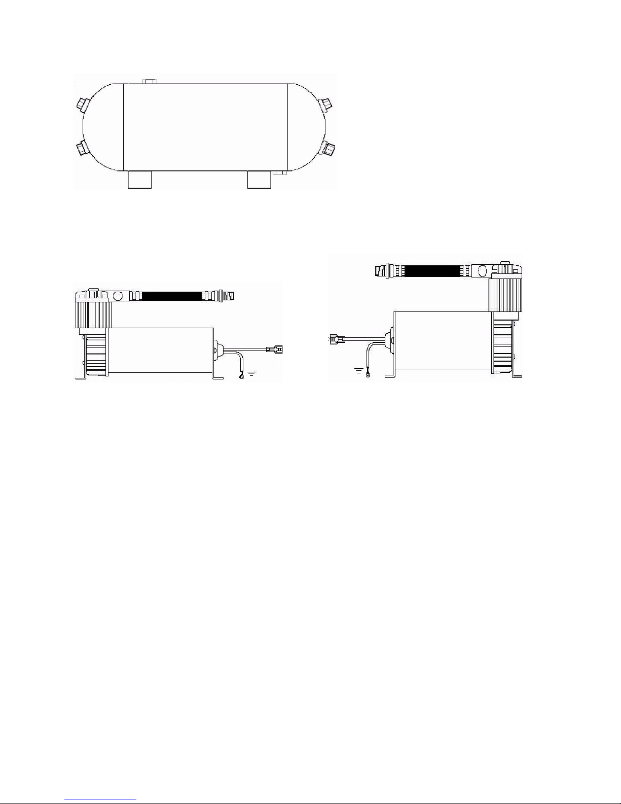
1 . To remove hose from the hose bracket, simply press down on the hose clamp release
tab to release bracket clamp.
11. Tie compressor’s positive lead wires together and connect to pressure switch lead.
12. Make sure that your compressor setup is properly fused. Dual 325C compressors
pull approximately 4 maximum amps of power.
13. Always locate fuse as close as possible to power source.
14. Before connecting to power source, check to make sure that all connections are
made properly.
15. Connect and test compressor system by running the compressor for a short time to
build up pressure in your air tank.
16. Once air pressure reaches preset cut out pressure of your pressure switch, the
compressor will shut off. Inspect all air line connections for leaks with soap and
water solution. If a leak is detected, the air line may not be cut squarely or pushed all
the way in. Tighten connections if needed.
COMPRESSOR OPERATING INSTRUCTIONS
IMPORTANT: The compressors have a maximum working pressure of 15 PSI. Always
operate the compressor at or below the MAXIMUM PRESSURE RATING of the
compressor. Operation exceeding maximum pressure ratings and or duty cycle will
result in damage to air compressor.
1. Your air compressor is equipped with an AUTOMATIC THERMAL OVERLOAD PROTECTOR.
This feature is designed to protect the air compressor from overheating and causing
permanent damage to your air compressor. The thermal overload protector will
automatically cut off power to your air compressor should the internal operating
temperature of the air compressor rise above safe levels during excessive use.
2. Should at any time during use, your air compressor automatically shuts of – do not
attempt to restart the air compressor. Turn power switch to the air compressor to the
OFF position. The automatic thermal overload protector will automatically reset when
internal temperature of the air compressor drops below safe level. After allowing air
compressor to cool off for about 3 minutes, you can safely resume use of the air
compressor by turning on the air compressor.
3. To prevent discharge of your vehicle’s battery and to provide peak performance, we
strongly recommend that you keep the vehicle’s engine running while using the air
compressor.
4. ONLY OPERATE AIR COMPRESSORS IN WELL VENTILATED AREAS.

C mpress r Maintenance & Repairs
1. Periodically check all electrical and fitting connections. Clean and tighten as
needed.
2. Periodically check all mounting screws. Tighten as needed.
3. Replace air filter element periodically. Replacement frequency depends on operating
frequency and operating environment. For frequent use in dusty environment, you
should replace air filter element more often.
4. Regularly clean dust and dirt from compressor.
5. Your air compressor is equipped with a permanently lubricated, maintenance free
motor. Never lubricate compressor.
6. Repairs should be performed by Manufacturer or Manufacturer’s Authorized Service
Agencies only.
CAUTION: Never touch the air compressor or fittings connected to the air compressor
with bare hands during or immediately after use. Leader hose and fittings will become
very HOT during and after use.
C mpress r Installati n Tips
1. Always use the remote intake filter option when possible. This will extend the
service life of your compressor.
2. If noise reduction from vibration is desired, using the remote mount option for the
inlet filter can reduce operation noise by up to 25%.
3. Always mount the compressor at a point higher than the inlet port of the tank. This
will keep moisture from being able to seep back to the tank.
4. When mounting the compressor, use a paint pen to mark the rubber isolators. While
the paint is still wet, stamp the compressor against the chassis to make an imprint of
exactly where to drill the mounting holes for the compressor.
Pressure Switch Installati n
Your VIAIR Onboard Air System comes complete with a heavy duty pressure switch that
will turn on the compressor at 11 PSI, and off at 145 PSI. The pressure switch has a
1/8” NPT inlet at the bottom that will fit directly into the provided T-fitting in the kit
(using thread sealant) to allow it to be plumbed into your air tank. (Use contents of
Package # 3 for this installation step)

Pressure Switch Installati n Tips
1. Both terminals of the pressure switch are positive (+) leads. One is connected to the
compressor positive lead wire and the other to switched, fused power. Use of a relay is
always recommended.
2. Never install your pressure switch in direct line from the inlet port coming from
the compressor. Tank pressure could be misread by the pressure switch. Instead, mount
the pressure switch on the tank where it receives air pressure reading from deflected
air in the tank.
2. Never use a pressure switch that is rated beyond your compressor’s rated Maximum
Working Pressure (15 PSI).
3. Replace with Pressure Switch with Relay P/N 9 217 if the pressure switch becomes
faulty or fails in the future.
Dash Panel Gauge Installati n
Your VIAIR Onboard Air System comes complete with a Dash Panel Gauge to monitor the
pressure of your 2. gallon VIAIR air tank. Additionally, the Dash Panel Gauge has an
ON/OFF switch preinstalled that will allow you to turn the system off by cutting
power to the pressure switch with relay that you have already installed. We
recommend that you install a master ON/OFF switch to allow the system to be turned
off any time you anticipate leaving the vehicle parked for any length of time, and to
avoid draining the vehicle’s battery unnecessarily due to a slow air leak in your
system. (Use contents of Package #4 for this installation step).
IMPORTANT: Each Dash Panel Gauge has been tested and calibrated. The air inlet on
this gauge has a factory installed compression fitting. DO NOT attempt to tighten or
loosen the body of this compression fitting. Any adjustments will cause the gauge to

malfunction and void warranty. The Dash Panel Gauge included in this kit is rated for
15 PSI. Do not pressurize gauge over 15 PSI.
1. Select M unting L cati n f r Dash Panel Gauge
Select a mounting location with a rigid mounting surface such as the bottom edge of
the dashboard. Use the gauge mounting panel as a template; mark off two mounting
points to be drilled. Carefully drill two 13/64” diameter holes as marked. Do not mount
Dash Panel Gauge at this time.
2. Air Line C nnecti n t Dash Panel Gauge
Remove only the collar of the compression fitting from the back of the Dash Panel
Gauge. Do not loosen of tighten the body of the compression fitting, which is
permanently affixed to the air inlet of the gauge. Insert air line tubing through this
collar, and then push air line tubing onto the barb of the compression fitting until the
air line completely covers the barb. Tighten collar onto the body of the compression
fitting with a wrench.
3. R uting Air Line t Air S urce
Route the air line tubing on the Dash Panel Gauge to the air source. Do not cut air
line yet. In some cases a hole may need to be drilled to enable the air line to pass
through to the air source. Make sure that the air line tubing is protected from any
sharp edges of the drilled hole using grommet strip supplied. Connect to the tank using
the 1/4” compression fitting supplied.
Installati n Tips:
• When cutting air line tubing, always cut as squarely as possible. Use a hose cutter or
razor blade.
• When routing air line tubing, always remember to avoid sharp edges, heat sources and
tight bends. (Air line must be routed at least 12 inches from exhaust systems & other
heat sources.)
IMPORTANT - Drilling through firewall: Always be sure of what is on the other side of
the firewall before drilling. Take care not to damage your vehicle’s electronic systems
or components when drilling.
4. Wiring the ON/OFF Switch
See Installation Diagram for electrical connections.
5. Wiring the Dash Panel Gauge f r Illuminati n

There are two wires, one red and one black connected to the light bulb of the gauge.
Connect the red wire to a suitable fused dash panel circuit. Use the quick splice
connector included in the kit for wire connections. The black wire is to be connected
to a suitable ground source.
6. M unting the Dash Panel Gauge
With all electrical and air line tubing routed and connected properly, mount the dash
panel gauge using the two 13/64” nuts, bolts, and washers included with the Dash
Panel Gauge. Make sure that no electrical wires or air line can be contacted by
vehicle pedal operation, or by use of any safety equipment.
7. C nnect t P wer S urce
Before connecting the power wire to a power source, check to make sure that the
ON/OFF switch on the dash panel gauge is in the OFF position. Connect the ring terminal
of the power wire to power source. (This is the wire described in Step 4, which is
connected to the ON/OFF switch of the dash panel gauge.)
8. Testing Y ur Onb ard Air System Run the compressor to build pressure in the air
tank. When air pressure reaches the pressure switch cut out pressure, the compressor
will shut off. Inspect all air line connections for leaks with soap and water solution
and spray with a spray bottle onto connections. If leaks are detected, air line may not
be cut squarely or pushed all the way in. Periodically check your system’s fittings in
this manner should your compressor turn on more often than normal without frequent
air use.
INLINE PRESSURE REGULATOR INSTALLATION INSTRUCTIONS
Your Onboard Air System comes complete with an adjustable inline air pressure
regulator that may be used to regulate the pressure in your air tank down to any
pressure below 15 PSI. This is especially useful for installations that will supply air
to a locking differential, or may be used to operate air tools. Never attempt to use the
regulator to adjust any tank pressure over 15 PSI, since the component is only rated
to a maximum of 15 PSI. (Use contents of Package #6 for this installation step).
1. M unting the Inline Pressure Regulat r
Select a mounting location with a rigid mounting surface such as the bottom edge of a
chassis. Use the inline pressure regulator mounting bracket as a template to mark the
two mounting points to be drilled. Carefully drill the two holes as marked, but do
mount the Pressure Regulator at this time.
2. Air Line C nnecti ns t Inline Pressure Regulat r

Use a 1/4” NPT compression fitting on the “IN” side of the regulator receiving air from
the air tank. On the “OUT” side of the regulator, you may install a 1/4” NPT quick
connect coupler, or use another 1/4” NPT compression fitting to route the air line to
the source of the item that pressure is being regulated to. If you are plumbing to air
locking differentials, we have included two 1/8” BSP Female to 1/4” NPT Male Adapters
for this use. You may require a T-fitting (not included), depending on your application.
3. Adjusting pressure 0-150 PSI
The pressure regulator knob locks when pushed towards the unit. To adjust pressure,
simple pull knob away from the regulator body and adjust as needed. Always lock the
adjustment knob in place before using pressure-adjusted air supply to keep pressure
regulated at a fixed pressure.
TIRE INFLATION GUN
OPERATING INSTRUCTIONS
Your Onboard Air System also comes with a Tire Inflation gun for airing up tires, and
adding compressed air to any inflatable item with a valve stem. The Tire Inflation Gun

has a normally closed lever style air chuck at the end of its rubber hose. After
connection to an air source such as an air tank via the quick connect stud preinstalled
in the unit, air may be discharged from the gun by simply squeezing the inflation
trigger. To check air pressure, simply release the trigger and check the onboard air
pressure gauge. (Use contents of Package #7 for this installation step).
1. Using the Tire Inflati n Gun:
Using a 1/4“ Quick Coupler, connect the Tire Inflation Gun to an air hose and connect
to a tire valve stem or similar inflation collar by securing the folding lever on the
Inflation Gun air chuck.
2. Filling Tires and ther Inflatable Items:
Squeeze the Inflation Trigger on the Inflation Gun by pressing it towards the handle of
the gun. This will allow stored air from the air tank to flow through the gun and
through the chuck into your tire or other inflatable.
3. Checking Tire Pressure:
To check tire pressure, release Inflation Trigger on Inflation Gun and allow the
needle of the -2 PSI gauge to settle. Tire pressure will be able to be read only
when the inflation trigger is released.
WARNING:
• Never operate the Inflation Gun at any pressure exceeding 15 PSI.
• Use caution when attached or removing air chuck from valve stems.
• Always ensure that tire valve stems are tight before inflating tires.
• Be careful to never inflate any tire or other inflatable past its rated pressure to
avoid explosion, or possible injury or death.
Please N te: Not intended for use with regular portable compressors or units meant to
be operated with an open ended air chuck. The Tire Inflation Gun is equipped with a
close ended chuck and will hold pressure back, which could cause the hose to burst.

P/N 10008 – SUPER DUTY ONBOARD AIR SYSTEM
INSTALLATION DIAGRAM

LIMITED WARRANTY

VIAIR CORPORATION WARRANTS THIS PRODUCT, WHEN PROPERLY INSTALLED AND UNDER
NORMAL CONDITIONS OF USE, TO BE FREE FROM DEFECTS IN WORKMANSHIP AND
MATERIALS FOR A PERIOD OF ONE YEAR FROM PROVIDED DATE OF PURCHASE. FOR
REPAIRS OR TO RECEIVE A REPLACEMENT, RETURN THE COMPLETE UNIT ALONG WITH
PROOF OF PURCHASE TO THE RETAILER FROM WHOM IT WAS PURCHASED. RETURNS
SHOULD BE MADE WITHIN THE TIME PERIOD AND CONDITIONS OF THE RETAILER’S POLICY
FOR EXCHANGES. IF YOU ARE UNABLE TO CONTACT YOUR DEALER, CONTACT VIAIR
DIRECTLY FOR REPAIRS OR REPLACEMENT AT OUR OPTION.
P/N 10008 – SUPER DUTY ONBOARD AIR SYSTEM VIAIR CORPORATION
15 EDELMAN
IRVINE, CA 92618
TEL: (949) 585-0011 FAX: (949) 585-0188
www.viairc rp.c m
PLEASE NOTE: THIS WARRANTY COVERS PRODUCT DEFECTS ONLY. IT DOES NOT COVER
INCIDENTAL OR CONSEQUENTIAL DAMAGES AS RESULT OF MISUSE OR ABUSE.
This manual suits for next models
1
Table of contents
Other VIAIR Air Compressor manuals

VIAIR
VIAIR 10000 User manual

VIAIR
VIAIR 250C-IG User manual

VIAIR
VIAIR 50001 User manual

VIAIR
VIAIR 70P User manual

VIAIR
VIAIR 380C User manual

VIAIR
VIAIR 450P-RVS User manual

VIAIR
VIAIR 40045-400P-A User manual

VIAIR
VIAIR 45043 EXTREME SERIES User manual

VIAIR
VIAIR Exreme Series User manual

VIAIR
VIAIR 300P SXS PORTABLE POWERSPORT Series User manual

VIAIR
VIAIR 325C User manual

VIAIR
VIAIR 93 User manual

VIAIR
VIAIR VMS 444DB User manual

VIAIR
VIAIR POWER SPORT Series User manual

VIAIR
VIAIR EXTREME Series User manual

VIAIR
VIAIR SPORT COMPACT Series User manual

VIAIR
VIAIR 15010 User manual

VIAIR
VIAIR 85 User manual

VIAIR
VIAIR 450P-A User manual

VIAIR
VIAIR 325C User manual