Metasys TC-9100 Series Service manual

System 91 Manual
TC-9100 Universal Controller
Technical Bulletin
Issue Date 0306
©2006 Johnson Controls, Inc. 1
Order No. MN-9100-2120
TC-9100 Universal Controller
Introduction Page 3
•Controller Hardware Models 4
•Modes of Operation 5
Software Configuration 9
•Analog Input Configuration (AI1 to AI4) 10
•Digital Input Configuration (DI1 and DI2) 13
•Output Module Configuration (OCN1 to OCN7) 14
•Programmable Module Configuration (PM1 to PM6) 24
•External Analog Input Configuration (XAI1 to XAI6) 39
•Low Limit (Anti-freeze) Module Configuration 40
•Summer/Winter Compensation Module 41
•Auto-dial Feature 42
•Supervisory Functions and Configuration 43
•Configuration for a TM-9180 Room Command Module 47
Installation 49
•Mounting 49
•Wiring 50
•Jumper and Switch Selections 56
•Startup 57
•Commissioning 57
Specifications & Technical Data 59
•Ordering Codes 60

2 Technical Bulletin—TC-9100 Universal Controller
Appendix 1: TC-9100 Item Descriptions and Tables 61
•Table 1: Item List 63
•Table 2: Programmable Module Algorithms 77
Appendix 2: Configuration Worksheets 85
•Worksheet 1: Connections 86
•Worksheet 2: Configuration Parameters – Programmable Modules 87
•Worksheet 3: Configuration Parameters – Input/Output and General 88

Technical Bulletin—TC-9100 Universal Controller 3
Introduction
The TC-9100 Universal microprocessor-based DDC Controller provides
room temperature control and is designed for use with HVAC terminal
units having a heating and/or cooling function, with and without fan-
assisted air circulation or flow control by damper positioning.
Applications include fan coil units, hot-water radiators and cold ceilings,
variable air volume (VAV) units, and small air handling units.
The controller is fully configurable to provide a wide range of control
strategies using its four analog inputs to measure temperatures and flow
rates, its two digital inputs to detect environmental conditions such as
space occupancy, window opening or fan failure, and its seven analog or
binary outputs to control heating, cooling and air flow control devices. A
RS-1100 or TM-9180 series room command module provides set point
adjust capabilities and a temporary occupancy override of the
COMFORT, STANDBY and NIGHT operating modes of the controller.
The TM-9180 can also provide local time scheduling of the operating
mode when the controller is not overridden by a supervisory system. The
controller has a low limit temperature protection feature and automatic set
point compensation for the winter and summer seasons.
When connected to a communications bus, the controller provides
operating data to a supervisory system, which also allows a user to
modify control set points and to set the operating mode of the controller
either manually or according to a time schedule.
The TC-9100 controller is part of the System 91 series of controllers and
is fully compatible with the Metasys network system. The compact size
of the controller makes it easy to mount within the terminal unit housing,
above a false ceiling or within a small control cabinet.
2667 2335
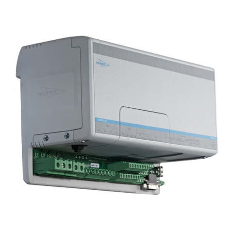
Figure 1: TC-9100 Universal
Controller
Figure 2: RS-1160 Room
Command Module

4 Technical Bulletin—TC-9100 Universal Controller
2333
Figure 3: TM-9180 Room Command Module
Note: The TM-9180 Room Command Module is only available as a
replacement part from July 2006.
There are two models of the TC-9100 Universal Controller. Each model
is available with fixed terminals or separable terminals.
Table 1: Controller Inputs and Outputs
Inputs/Outputs Qty. Type of Signal Model
Analog Inputs 4 0 - 10 VDC
Digital Input 1
Digital Input 2
1
1
Dry contact or HX-9100-8001
Condensation Sensor
Dry contact
Models 1 and 2
Mode Contact
(Occupancy Button)
1 Dry momentary contact
LED Mode Signal 1 Voltage for LED in RS-1100
Series
Analog Output 1a/b
(Heating/Cooling)
Analog Output 2
2
1
0 - 10 VDC
0 - 10 VDC
Model 1 only
Digital Outputs
(PAT, DAT, 2-Stage
On/Off, and On/Off)
5 Triac rated at 24 VAC
(switched only - no power
supplied)
Digital Outputs
(PAT, DAT, 2-Stage
On/Off, and On/Off)
7 Triac rated at 24 VAC
(switched only - no power
supplied)
Model 2 only
Power Supply 1 24 VAC Models 1 and 2
For detailed information about the physical characteristics of the inputs
and outputs, refer to the Specifications and Technical Data section further
in this document.
For detailed information about the configuration possibilities, refer to the
appropriate Software Configuration section further in this document.
Controller
Hardware
Models

Technical Bulletin—TC-9100 Universal Controller 5
Note 1: Digital inputs 1 and 2 may be used with any sensor that
provides a dry (voltage-free) and isolated contact, suitable for
low-voltage (24 V) switching. Digital Input 1 may also be used
with the Johnson Controls Condensation Sensor, code number
HX-9100-8001. No other condensation sensor may be used
except a sensor which provides a dry contact that is isolated
from all other electrical circuits.
Note 2: The TC-9100 controller is compatible with the RS-1100 series
of room modules for room temperature, remote set point and
temporary occupancy mode change inputs. The controller is
also compatible with the TM-9180 Room Command Module,
which also provides 3-speed fan override and operating mode
override. Only one RS-1150/RS1160 series module with an
occupancy mode button or only one TM-9180 may be
connected to the controller.
The TC-9100 Universal Controller can operate in any of the following
modes:
•Standalone mode
•Alternate mode
•Supervisory mode
•Low Limit (Anti-freeze) mode
•Summer/Winter Compensation mode
•Auto-dial mode
When the TC-9100 Universal Controller is not connected to a supervisory
system via the communications bus, nor to a TM-9180 Room Command
Module with LCD display, it will operate in one of three operating
modes, which are indicated on the RS-1150/RS-1160 Room Command
Module, as follows:
•COMFORT (room occupied): LED on steady
•STANDBY (room unoccupied): LED flashing
•OFF (room not in use): LED off
The Operating mode is determined by the status of the digital inputs when
configured as Window Contact or Occupancy Sensor, and may be
modified by the occupancy button on the RS-1100 series Room
Command Module as shown in Table 2. When not assigned to a digital
input, the Window Contact function is assumed to be Window Closed,
and the Occupancy Sensor function is assumed to be Occupied.
Modes of
Operation
Standalone
Mode

6 Technical Bulletin—TC-9100 Universal Controller
Table 2: Standalone Modes
Input States: Resulting Modes:
Window Contact Occupancy Sensor Operating Mode
Alternate Mode
(Occupancy
Button)
Open No Action OFF No Action
Closed Occupied COMFORT STANDBY
Unoccupied STANDBY COMFORT
Depending on the way that the controller is configured, the COMFORT,
STANDBY, and OFF modes may change the Working Set Point (WSP)
of any control module, and the OFF mode may be configured to override
the output of each control module to close off the heating, cooling, or air
flow devices.
For further details, refer to the subheading Controller Algorithms 1-6 –
General under the Programmable Module Configuration section of this
document.
Controller Digital Output Number 7 may be configured to switch on in
COMFORT mode for auxiliary circuit control, such as individual room
lighting. For further details, refer to the Output Module Configuration
section of this document.
The Alternate mode is activated and reset by a momentary contact
connected to the mode input terminals of the controller. This contact is
provided by the occupancy button of the RS-1150/RS-1160 Room
Command Module.
The occupancy button on the TM-9180 Room Command Module can also
provide this function via the room command module communication
interface instead of the hard-wired contact.
When pressed for approximately one second, the occupancy button
changes the operating mode of the controller to the Alternate mode, or
back to the normal operating mode as shown in tables 2 and 3. The
COMFORT (T) mode is active only for a period of one or two hours
(dependent on the configuration: see the Supervisory Mode Configuration
section), after which the controller automatically resets to the normal
operating mode.
Note: Only one RS-1100 module with an occupancy button or only one
TM-9180 may be connected to the controller.
When connected to a supervisory system via the communications bus, or
to a TM-9180 Room Command Module, the controller may operate in
COMFORT, STANDBY or OFF operating modes, and additionally in
NIGHT mode. These modes are indicated on the TM-9180 or RS-1100 (if
connected), as follows:
•COMFORT (room occupied): LED on steady,
•STANDBY (room unoccupied): LED flashing,
Alternate Mode
Supervisory and
TM-9180 Modes

Technical Bulletin—TC-9100 Universal Controller 7
•NIGHT (scheduled or manually set unoccupied): LED off,
•OFF (room not in use): LED off.
The Operating modes are set by the supervisory system and are modified
by the Window Contact and Occupancy Sensor inputs (if configured),
and by the occupancy button on the room command module, as shown in
Table 3. The Window Contact input always switches the controller to
OFF mode, and a MANUAL mode command from the supervisory
system overrides the action of the Occupancy Sensor and occupancy
button.
Table 3: Supervisory Modes
Input States: Resulting Modes:
Window
Contact
Supervisory Mode Occupancy
Sensor
Operating
Mode
Alternate Mode
(Occupancy
Button)
Open Any Mode No Action OFF No Action
OFF Occupied OFF OFF
Unoccupied OFF OFF
NIGHT Occupied NIGHT COMFORT (T)
Unoccupied NIGHT COMFORT (T)
STANDBY Occupied STANDBY COMFORT
Closed Unoccupied STANDBY COMFORT (T)
COMFORT Occupied COMFORT STANDBY
Unoccupied STANDBY COMFORT
OFF/MANUAL OFF
NIGHT/MANUAL No Action NIGHT No Action
STANDBY/MANUAL STANDBY
COMFORT/MANUAL COMFORT
Depending on the way that the controller is configured, the COMFORT,
STANDBY, NIGHT and OFF modes may change the Working Set Point
(WSP) of any control module, and the OFF mode may be configured to
override the output of each control module to close off the heating,
cooling, or air flow devices.
For further details, refer to the subheading Controller Algorithms 1-6 –
General under the Programmable Module Configuration section of this
document.
Supervisory systems available from Johnson Controls include the
NCM 311/361 in the Metasys Network System, the CS-9105 Control
Station, and the Companion System.
Note: A supervisory system which is setting the operating mode of the
controller will have priority over a locally connected TM-9180
Room Command Module.

8 Technical Bulletin—TC-9100 Universal Controller
The TC-9100 Universal Controller may be configured to set any of the
analog outputs to the maximum level, or switch any of the digital outputs
on, when a low level in an analog input is sensed. This feature is normally
used for low-limit temperature or anti-freeze protection in rooms by
switching on heating devices. The Low Limit mode overrides the OFF
mode of the controller and the manual override of the 3-speed fan
outputs.
Note: As the Low Limit mode is dependent on application and
configuration, the equipment installer is responsible for ensuring
that appropriate additional anti-freeze devices have been installed
to cover all possible low temperature situations which may cause
equipment damage.
For further details, refer to the Low Limit Module Configuration section
of this document.
The working set points in the TC-9100 Universal Controller may be
increased in summer and decreased in winter to provide additional energy
savings when it is possible and appropriate to modify comfort conditions
in the controlled space.
Alternatively, in winter, the set points may be increased to offset the
effect of “cold radiation” from external wall surfaces.
For further details, refer to the Summer/Winter Compensation Module
Configuration section of this document.
The TC-9100 Universal Controller may signal to a supervisory system
that any one or more of the following off-normal conditions has occurred:
•Analog Input High or Low Limit alarm
•Window open
•General alarm
•Low Limit (Anti-freeze) mode is active.
This signal may be used to initiate further actions, such as an automatic
dial connection to a remote monitoring system. The N2 Dial Module
(NDM101) within the Metasys System provides this function. For further
details, refer to the section of this document titled Auto-dial Feature.
Low Limit
(Anti-freeze)
Mode
Summer/Winter
Compensation
Auto-dial Mode

Technical Bulletin—TC-9100 Universal Controller 9
Software Configuration
The software operating system of the TC-9100 Universal Controller
contains a number of modules which can be given operating and
configuration parameters and connected together to perform the desired
control function. Some of the modules condition physical inputs to
provide data to other controlling and calculation modules, and some
modules control the physical outputs, and the behaviour of all modules is
determined by the operating parameters. The modules are shown
graphically in Appendix 2 – Worksheet 1 – Connections, and the
configuration of each type of module is described in detail in the
following sections.
Parameter and connection data are stored in memory locations known as
“Items.” A complete list of all the Items is given in Appendix 1 – Table 1.
All Items have an address (given in hexadecimal and decimal notation)
and a tag for easy identification. Some Items contain analog information
in the form of numbers, some contain logical information in the form of
eight binary states (one byte) or 16 binary states (two bytes), and some
contain an integer number which is the address of another Item and
defines a “connection” between modules. The source of the connection is
the Item address of the analog output of a module and the destination of
the connection is the Item address of an analog input of a module. The
input (or destination) Items are identified by a tag with the “@” character.
For example, the output of the module which measures Analog Input
Number 1 is found at Item Address 01, and has the tag name AI1. The
first input of Programmable Module Number 5 is found at Item Address
54 (hex) or 84 (decimal), and has the tag name PM5I1@. By entering the
value 01 in Item Address 54 (hex), a connection is made, whereby the
value of AI1 is transferred to the first input of Programmable Module
Number 5 as shown below:
01
PM5I1@AI1
01
54
Value
Connections to output modules are specified as part of the configuration
parameter item for each module. The first 5 bits contain the Item address
of the source of the connection. For example, when the Item Address 0A
(hex) is entered into the first 5 bits of Item Address 78 (hex) or 120 (dec),
the following connection is defined:
0A
OCN3OCM1
0A
78 Output 3Value
Worksheet 1 in Appendix 2 can be used to develop a control strategy by
making all the required connections graphically. The connection
information can then be entered into the Item address locations in
Worksheets 2 and 3. The parameters and data to define the operation of
the various software modules can also be entered into these worksheets.
Preparing a
Configuration

10 Technical Bulletin—TC-9100 Universal Controller
When the worksheet has been completed, the data can be physically
entered into the controller using the SM-9100 Service Module, which
plugs into the side of the controller (or by connecting a PC to the N2 Bus
serial link and running the M9101 Configuration and Commissioning
Software Package). Using either tool, the data for each Item address is
entered in turn. When complete, the controller operation may be
monitored by displaying the Item addresses that contain the dynamic
parameters of each module of the controller, such as analog input values,
programmable module output values, or the Controller modes of
operation.
Note: It is recommended that the controlled equipment be switched off
when configuration parameters are being changed to avoid any
unexpected control actions.
The TC-9100 Universal Controller has four analog inputs, each accepting
a 0 to 10 VDC input signal. The inputs are conditioned in software using
configuration parameters to provide a numerical value representing the
physical quantity being measured, such as temperature, relative humidity,
or flow rate. The numerical value can be used as an input to a
programmable module (configured as a Control Module or a Calculation
Module), and can be read by a supervisory system. Alarm limit values
may be set in the controller, as fixed configuration parameters or by a
supervisory system, and the high or low alarm status of each analog input
can be read by a supervisory system.
The parameters to be defined for each analog input are listed below.
Refer to Appendix 2 – Worksheet 3, or Appendix 1 – Table 1: Item List,
for the Item addresses. Note that nin the tag names in the table below
stands for the analog input number from 1 to 4.
Table 4: Analog Input Configuration Items
Item Tag Type Description
IOPn 1 Byte
Bit 4
Bits 7,6,5
Bits 8,3,2,1
Analog Input Options that define the conditioning of the
physical signal.
Defines the physical input type and must be set to 0 (zero)
for the voltage input.
000 = Linear Range (0 to 10 V)
010 = Square Root Range (0 to 10 V)
011 = Linear Range (2 to 10 V)
Set to 0 = not used.
HRIn Number
High Range for AIn: value represented by the highest
input signal (10 VDC). (See LRIn for analog value
calculation resulting from High and Low Range values.)
Continued on next page...
Entering a
Configuration
Analog Input
Configuration
(AI1 to AI4)
Configuration
Parameters

Technical Bulletin—TC-9100 Universal Controller 11
Item Tag
(Cont.)
Type Description
LRIn Number
Low Range for AIn: value represented by the lowest input
signal (0 or 2 VDC). This value must be 0 for an input with
the square root option. Use OFSn for zero offset correction.
The analog value is calculated as follows:
Linear:
AI = (PI% + OFS) / 100 x (HRI - LRI) + LRI
Square Root (LRI = 0):
(
)
AI (PI% + OFS) 100 HRI=×
where:
AI = Analog value
PI% = Analog input in % of the physical input range
(10 VDC, or 8 VDC for 2 to 10 V linear)
OFS = Offset Value
OFSn Number
Offset Value for AIn:
value added to the analog input in %
of the physical input range. This parameter is normally
used to offset an input to the square root range from a
differential pressure transducer, for example, where the
output of the transducer is not at “true zero” (0 or 2 VDC)
when the physical differential pressure is zero. (See LRIn
for analog value calculation using OFSn.)
FTCn Number
Filter Time Constant:
(in seconds) to reduce cyclic
instability or rapid changes in the analog input. The effect
of the filter is as follows:
AIt= AIt-1 + [1 / (1 + FTC)] x (AI - AIt-1)
where:
AIt= Filtered analog value at current time
AIt-1 = Filtered analog value at previous poll
AI = Actual analog value at current time
If FTC = 0:
AIt= AI
HIAn Number
High Alarm Value for AIn:
if no high limit is required, enter
a number greater than HRIn.
LOAn Number
Low Alarm Value for AIn:
if no low limit is required, enter
a number lower than LRIn.
If an analog input is configured but not connected to a sensor, install a
wire jumper between the input terminal and the analog common terminal
to keep the analog input at its low range value.

12 Technical Bulletin—TC-9100 Universal Controller
The parameters that are dynamically generated by the controller from the
analog inputs using the configuration parameters are listed below:
Table 5: Analog Input Dynamic Items
Item Tag Item Address
(Hex/Dec)
Description
AI1 01/01 Analog Input 1 Value
AI2 02/02 Analog Input 2 Value
AI3 03/03 Analog Input 3 Value
AI4 04/04 Analog Input 4 Value
AIH1 1E/30, Bit 1 1 = Analog Input 1 High Alarm
0 = No high alarm
AIL1 1E/30, Bit 2 1 = Analog Input 1 Low Alarm
0 = No low alarm
AIH2 1E/30, Bit 3 1 = Analog Input 2 High Alarm
0 = No high alarm
AIL2 1E/30, Bit 4 1 = Analog Input 2 Low Alarm
0 = No low alarm
AIH3 1E/30, Bit 5 1 = Analog Input 3 High Alarm
0 = No high alarm
AIL3 1E/30, Bit 6 1 = Analog Input 3 Low Alarm
0 = No low alarm
AIH4 1E/30, Bit 7 1 = Analog Input 4 High Alarm
0 = No high alarm
AIL4 1E/30, Bit 8 1 = Analog Input 4 Low Alarm
0 = No low alarm
An alarm bit is set when the analog value is equal to the high or low
alarm value, and the alarm bit is cleared when the analog value comes
back into normal range by at least 2% of the range of the analog input,
defined by [HRI - LRI].
Low Alarm Value
2% of rangeNo alarm
Differential =
2% of range
No alarm
Low Alarm
High
Alarm
AI Value
High Alarm Value
Time
Figure 3: High and Low Alarms
When an analog input goes into high or low alarm, the DIAL Item bit is
set. For details, refer to the section titled Auto-dial Feature in this
document.
Dynamic
Parameters

Technical Bulletin—TC-9100 Universal Controller 13
The TC-9100 Universal Controller has two digital inputs, labeled DI1 and
DI2, each connecting to an isolated, voltage-free contact. DI1 may also be
connected to a Condensation Sensor, Order Code HX-9100-8001, which
provides the equivalent of an open contact when the sensor is dry and a
closed contact when water condensation is sensed.
By configuration, the digital inputs are set to provide any two of the
Logic modes in the controller which each have a specific function in the
controller operation. The status of the Logic modes can be read by a
supervisory system.
The parameters to be defined for each digital input are listed below. The
Item TCS2 is included in Worksheet 3 of Appendix 2.
Table 6: Digital Input Configuration Items
Item Tag Type Description
TCS2 2 Bytes
Bits 11,10,9
Controller Options 2
.
Define
Digital Input DI1 Logic mode
, as follows:
000 = Input not used.
001 = Connected to a window contact for “Window
Open” mode.
010 = Connected to an occupancy sensor for
“Occupancy” mode.
011 = Connected to an air quality sensor, condensation
sensor, or other sensor with override function for
“Air Quality / Override” mode.
100 = Connected to a contact to change the action of
one or more control modules for “Reverse Action”
mode.
101 = Connected to a general purpose alarm contact for
“General Alarm” mode. This mode has no effect
on the operation of the controller and is used for
supervisory system purposes only.
Bit 12 Defines the action of the contact connected to DI1.
0 = “Open” contact sets the mode.
1 = “Closed” contact sets the mode.
For example, for a “window” contact that opens when the
window is open, set this bit to 0. For an “occupancy” sensor
contact that closes to indicate occupancy, set this bit to 1.
Bits 15…13
Define
Digital Input DI2 Logic mode
, using the same bit
patterns as shown above for DI1, bits 11, 10, 9.
Bit 16 Defines the action of the contact connected to DI2, the
same as shown above for DI1, Bit 12.
The Logic mode set for DI2 must be different from the Logic mode of
DI1 to avoid interference between the contacts. If an input is not used, set
the Logic mode bits to 000. If a Logic mode is configured but no sensor
contact is connected, install a wire jumper between the digital input
terminals.
Digital Input
Configuration
(DI1 and DI2)
Configuration
Parameters

14 Technical Bulletin—TC-9100 Universal Controller
The Window Open and Occupancy modes are always active, if defined,
and influence the controller operating mode (see tables 2 and 3). The Air
Quality / Override and Reverse Action modes are only active for the
control modules within which they are enabled. Programmable modules
configured as Algorithm 7 to 12 (calculation modules) can be conditioned
by one or both of the configured logic modes, enabling the digital inputs
to be part of the calculation function (see Programmable Modules
Configuration – Calculation Algorithms).
The parameters that are dynamically generated by the controller from the
digital inputs using the configuration parameters are listed below:
Table 7: Digital Input Dynamic Items
Item Tag Item Address
(Hex/Dec)
Description
WIN 20/32, Bit 6 1 = Window open.
0 = Window closed.
OCC 20/32, Bit 7 1 = Occupied status.
0 = Unoccupied status.
AIRQ 20/32, Bit 8 1 = Air quality poor, condensation detected, or other
override condition.
0 = No override condition.
REVL 26/38, Bit 3 1 = Reverse control action of enabled control
modules.
0 = Use configured control action in enabled modules.
ALM 26/38, Bit 5 1 = General purpose alarm or status.
0 = Normal status.
When a Window Open or General Alarm status is detected, the DIAL
Item bit is set. For details, refer to the section titled Auto-dial Feature in
this document.
The TC-9100 Universal Controller has seven output modules. Output
modules OCN1 and OCN2 drive analog outputs or digital outputs,
depending on model number. Output modules OCN3 to OCN7 drive
digital (triac) outputs in both models.
Model TC-9100-x000 has analog outputs, and OCN1 and OCN2 must be
configured for 0-10V analog outputs. (The option for solenoid valve
driver module outputs is no longer used.)
Model TC-9100-x001 has all digital (triac) outputs, and OCN1 and
OCN2 must be configured for one of the digital output options: as a pair
for Position Adjust Type (PAT), or 2-stage on/off output type, or as two
independent on/off outputs. OCN1 may also be configured as a Duration
Adjust Type (DAT) and OCN2 as an on/off type.
Dynamic
Parameters
Output Module
Configuration
(OCN1 to OCN7)

Technical Bulletin—TC-9100 Universal Controller 15
In both models the digital output pairs OCN3/OCN4 and OCN5/OCN6
can be configured as one of the digital (triac) output options mentioned
above for OCN1/OCN2. In addition, the digital outputs
OCN5/OCN6/OCN7 can be configured as a 3-speed fan controller, and
OCN7 has a special option as a “COMFORT” output signal when not
used in the 3-speed fan control option.
The output modules provide the interface between the output of a
programmable module and the hardware output. The status of the digital
(triac) outputs can be read by a supervisory system and can be switched
on and off directly by the supervisory system, overriding the output
module. Digital outputs are normally only controlled by a supervisory
system when not used in the controller configuration and provide a
convenient means of remote switching. Analog outputs cannot be read or
overridden by a supervisory system. However, the output of the
programmable module from which the output module receives its control
value may be read and overridden by a supervisory system (see
Programmable Modules Configuration).
The analog output type is only configurable in output modules OCN1 and
OCN2 must be configured for 0 - 10 VDC. (The option for a solenoid valve
driver module output is no longer used).
The analog hardware output for OCN1 has a special feature. There are in
fact two physical analog outputs that are labeled AO1a and AO1b. Only one
output can be active at one time and the other output will remain with a zero
output. These outputs are typically used in a heating/cooling application
with one controlled (process) variable, such as room temperature. AO1a is
used to control the heating equipment and AO1b is used to control the
cooling equipment, both of which directly influence the temperature
measured by the controlled (process) variable. In order to use this special
feature, the source control signal for OCN1 must come from a pair of
programmable modules configured as Algorithm 4 (heating/cooling PI
controller - single output). AO1a (heating) will be active when the first
module of the pair (loop 1) is active, and AO1b (cooling) will be active
when the second module of the pair (loop 2) is active. (See Programmable
Module Configuration – Algorithm 4 for details.)
If OCN1 is connected to a programmable module configured as an
Algorithm 2 or 6, only output AO1a will be active. If OCN1 is connected
to a programmable module configured as an Algorithm 7 to 13, only
output AO1b will be active.
Analog output OCN2 may be connected to any programmable module.
For all analog outputs, a range of 0 to 100% is assumed, where 0% gives
a zero output and 100% gives the maximum output (10 VDC). OCN1 and
OCN2 are not normally used with the on/off control algorithms 1, 3, and
5, since the output is either 0% or 100% and does not vary between these
two limits.
Analog Output
Type
(0 to 10 VDC)

16 Technical Bulletin—TC-9100 Universal Controller
The DAT output type may be configured in output modules OCN1,
OCN3, and OCN5. The DAT output is a digital output (triac) that is
switched on for a duration within the set heating or cooling valve cycle
time in direct proportion to the controller output from 0 to 100%. To
avoid unnecessary switching of the valve actuator when the output is
between 0 and 5% the digital output (triac) remains off, and when the
output is between 95 and 100% the digital output (triac) remains on. The
cycle time is set as a configuration parameter. DAT output modules may
be connected to any programmable module except those configured as
Algorithm 1, 3, or 5.
30% Output50% Output
OFF
ON
DAT Cycle Time DAT Cycle Time
Figure 4: DAT Output
The PAT output type may be configured in pairs of output modules –
OCN1/OCN2, OCN3/OCN4, and OCN5/OCN6.
The PAT output is a pair of digital outputs (triacs) that are switched on to
open and close an incrementally driven heating or cooling valve. The
duration of switching is directly proportional to the change in the
controller output and related to the full stroke time of the valve such that
a 100% change will completely open or close the valve. At the 0% or
100% position, the duration of switching is increased to ensure that the
valve is completely at its end position and the appropriate digital output is
switched on for the full stroke time every two hours to ensure that the
valve remains at its end position. To prevent unnecessary wear on the
actuator, the digital output will only be switched when the output change
exceeds the PAT dead-band (in % of full stroke) in the same direction as
the previous change, or twice the PAT dead-band if the direction of
change is reversed. The full stroke time and PAT dead-band are set as
configuration parameters. PAT output modules may be connected to any
programmable module except those configured as Algorithm 1, 3, or 5.
Duration Adjust
Type (DAT)
Position Adjust
Type (PAT)

Technical Bulletin—TC-9100 Universal Controller 17
The 2-stage on/off output type may be configured in pairs of output
modules – OCN1/OCN2, OCN3/OCN4, and OCN5/OCN6.
The output is a pair of digital outputs (triacs) that are switched on in
sequence as the controller output increases. The first stage digital output
is switched as soon as the output is above 0% and the second stage digital
output is switched when the output is equal to the set load rating for the
first stage, which is set as a configuration parameter along with the
switching differential.
Note: To ensure that the first stage switches off, the low limit of the
control module to which the 2-stage output module is connected
must be set at the switching differential value as a negative
number. For example, if the differential is set at 5%, then the low
limit of the control module must be set at -5%.
Two-stage output modules may be connected to programmable modules
configured as Algorithm 2, 4, or 6, or as calculation algorithms 7 to 12,
provided that the output range covers the switching differential, as
explained above.
}Differential
}Differential
Stages 1 and 2
Stage 1
Off
0
100
Module
Output
Process Variable
Load Rating
of Stage 1
Figure 5: 2-Stage On/Off Output
An on/off output type may be configured for output modules OCN1 to
OCN6. The output is a single triac that is switched on when its source
signal is greater than 0, and switched off when the source signal is equal
to or less than 0. The on/off output module is normally connected to a
programmable module configured as Algorithm 1, 3, or 5 (an on/off
controller), and the switching differential is provided by the on/off
controller.
2-Stage On/Off
On/Off Output
Type

18 Technical Bulletin—TC-9100 Universal Controller
The 3-speed fan controller output may be configured only in Output
Module OCN5, and it also uses OCN6 and OCN7.
The output is a set of three digital outputs (triacs) that are switched on in
turn at the three fan speed break points, set as configuration parameters.
The switching differential for all break points is also set as a
configuration parameter. The first output switches on at Break Point 1
and off at Break Point 1 less the switching differential. The second output
switches on at Break Point 2 and the first output is switched off. The third
output switches on at Break Point 3 and the second output is switched off.
Only one output is on at one time, and the switching differential is
applied to all on/off transitions.
The 3-speed fan controller output may be connected to any programmable
module except those configured as Algorithm 1, 3, or 5.
}Differential
}Differential
}Differential
Speed 3
Speed 2
Speed 1
Off
0
100
Module
Output
Process Variable
Break Point 1
Break Point 2
Break Point 3
Figure 6: 3-Speed Fan Output
When OCN5 is configured as a 3-speed fan controller, the source control
signal connection to OCN6 defines an analog input that overrides the
controller, as follows:
•Analog input value to OCN6 less than 0 ⇒Automatic mode
(3-speed fan module controlled by source defined in OCN5).
•Analog input value to OCN6 between 0 and 100 ⇒Override mode
(3-speed fan module controlled by analog input value to OCN6).
The output triacs switch at the defined break points and use the defined
switching differential in both Automatic and Manual modes. The
Override feature enables the manual control of fan speed using an analog
input connected, for example, to a switch assembly that generates the
voltage levels to force the appropriate fan speed or allow automatic
operation.
Alternatively, the TM-9180 can be used to override the 3-speed fan
controller. Refer to Configuration for a TM-9180 Room Command
Module, further in this manual, for configuration details.
3-Speed Fan
Controller
Output
3-Speed Fan
Override

Technical Bulletin—TC-9100 Universal Controller 19
Note 1: The Override mode is disabled when the controller is in Low
Limit (Anti-freeze) mode or in OFF mode. In this case, the 3-
speed fan controller operates in Automatic mode and responds
as required by the programmable module to which it is
connected.
Note 2: In controllers with Version 3 or later firmware (Date Code
9714 or later), the Override mode is also disabled in NIGHT
and STANDBY modes. The override is only active in
COMFORT mode.
Note 3: In controllers with Version 3 or later firmware (Date Code
9714 or later), a programmable module with a controller
algorithm (algorithms 1-6) can be configured to set its output to
0 % (or OFF) when the 3-speed fan override sets the fan to
OFF. This interlock is required for applications where heating
or cooling equipment must be switched off when there is no air
flow, such as in fan coil units with electric heating, direct
expansion coils or heat pumps. Refer to Configuration
Parameters for Controller Algorithms (PM Tag PMxTYP Bit
10), further in this manual, for details.
When Output Module OCN7 is not used by Output Module OCN5 as the
third speed of a 3-speed fan controller, the triac may be driven on when
the operating mode of the controller is COMFORT by setting Bit 8 in
Item TCS2 (Address 85 hex, 133 dec) to 1. This output can be used, for
example, for lighting control.
The parameters to be defined for each output module are listed below.
Refer to Appendix 2 – Worksheet 3, or Appendix 1 – Table 1: Item List,
for the Item addresses.
Note: Do not forget to set Item TCS2, Bit 6, according to the power
supply frequency of 50 or 60 Hz.
Table 8: Output Module Configuration Items
Item Tag Type Description
TCS2 Bit 6 Set to 1 if the power supply frequency is 60 Hz, or set to 0
for 50 Hz.
Bit 8 Set to 1 if OCN7 is not used for 3-speed fan control and
DO7 should be on when the controller is in COMFORT
mode.
OCN1 1 Byte
Output Module 1 Configuration
.
Bits 5…1
Source of Module
in binary code:
01010 (0A hex) = Output Module 1 (OCM1).
01011 (0B hex) = Output Module 2 (OCM2).
⇓
01111 (0F hex) = Output Module 6 (OCM6).
Continued on next page...
Output Module
OCN7
Configuration
Parameters

20 Technical Bulletin—TC-9100 Universal Controller
Item Tag
(Cont.)
Type Description
OCN1 Bits 8…6
Output Type
000 = Output not used.
Hardware analog outputs only:
001 = Not used. (Was for solenoid valve driver module.)
010 = 0 to 10 VDC output.
Hardware digital outputs (triac) only:
011 = On/off output.
100 = DAT output.
101 = PAT output (also uses OCN2 – define OCN2 as
“output not used”).
110 = 2-stage output (also uses OCN2 – define OCN2
as “output not used”).
OCO1 Number
Output Module 1 Parameter
.
When OCN1 is PAT = Full stroke time of actuator (sec.).
When OCN1 is DAT = Cycle time of actuator (sec.).
When OCN1 is 2-stage = Load rating of stage 1 (% of
module output).
OCN2 1 Byte
Output Module 2 Configuration
.
Bits 5…1
Source of Module
in binary code:
01010 (0A hex) = Output Module 1 (OCM1).
01011 (0B hex) = Output Module 2 (OCM2).
⇓
01111 (0F hex) = Output Module 6 (OCM6).
Bits 8…6
Output Type
000 = Output not used (or used with PAT or 2-stage
output defined in OCN1).
Hardware analog outputs only:
001 = Not used. (Was for solenoid valve driver module.)
010 = 0 to 10 VDC output.
Hardware digital outputs (triac) only:
011 = On/off output.
OCO2 Number
Output Module 2 Parameter
.
When OCN1 is PAT = PAT dead-band (%).
When OCN1 is 2-stage = Switching differential (%).
OCN3 1 Byte
Output Module 3 Configuration
.
Bits 5…1
Source of Module
in binary code:
01010 (0A hex) = Output Module 1 (OCM1).
01011 (0B hex) = Output Module 2 (OCM2).
⇓
01111 (0F hex) = Output Module 6 (OCM6).
Bits 8…6
Output Type
000 = Output not used.
011 = On/off output.
100 = DAT output.
101 = PAT output (also uses OCN4 – define OCN4 as
“output not used”).
110 = 2-stage output (also uses OCN4 – define OCN4
as “output not used”).
Continued on next page...
This manual suits for next models
4
Table of contents
Other Metasys Controllers manuals
Popular Controllers manuals by other brands
DERUN LIGHTING TECHNOLOGY
DERUN LIGHTING TECHNOLOGY DR-CON-IR20M-3CH-LV user manual

Leslie
Leslie 35 Installation, operating and maintenance instructions
AMX
AMX Tango DAS-T0804-SIG Specifications

Marlec
Marlec HRDi Installation & operation

Omega
Omega Linkr MOBILE Quick install guide
Kelly
Kelly KBL24101X user manual
