manuals.online logo
Brands
  1. Home
  2. •
  3. Brands
  4. •
  5. Marlec
  6. •
  7. Controllers
  8. •
  9. Marlec HRDi Guide

Marlec HRDi Guide

User Programming
Manufactured in the UK by
Marlec Engineering Co Ltd
Rutland House, Trevithick Rd, Corby, Northants, NN17 5XY UK
Tel: +44 (0)1536 201588
Email:sales@marlec.co.uk www.marlec.co.uk
Buons: (These buons become selectorsin programming mode)
Included in the box:
HRDi Controller
External temperature sensor
Installaon & Operaon Manual
Connecon Panel includes:
Ports for oponal remote display and external temperature
sensor supplied.
Wiring block for inputs from Windcharger (WG) and solar panels
(PV) and output to baery banks 1 and 2.
Charge / Stop Switch shown in
stop posion. Shut down for
installaon / maintenance.
Note: Do not operate in high winds
unl the turbine has been slowed
down or restrained and solar
panels covered or in darkness.
Install the HRDi upright on a flat
surface and secure using the 4 wall
mounng holes.
Venlaon slots must never be
obstructed, leave a minimum of
5cm around the unit to allow air
cooling.
Operang temperature: -10°C to + 40°C
(LCD 0°C to + 40°C )
RUTLAND HRDi
CHARGE REGULATOR
Installaon & Operaon
LIMITED WARRANTY
The Marlec Engineering Company Limited Warranty provides free replacement cover for all defects
in parts and workmanship for 24 months from the date of purchase. Marlec's obligaon in this
respect is limited toreplacing parts whichhave been promptlyreported to thesellerandare inthe
seller’s opinion defecve and are so found by Marlec upon inspecon. A valid proof of purchase will
be required if making a warranty claim.
Defecve parts must be returned by prepaid post to the manufacturer Marlec Engineering Company
Limited, Rutland House, Trevithick Road, Corby, Northamptonshire, NN17 5XY, England, or to an
authorised Marlec agent.
This Warranty is void in the event of improper installaon, owner neglect, misuse, damage caused
by flying debris or natural disasters including lightning and hurricane force winds. This warranty
does not extend to support posts, inverters, baeries or ancillary equipment not supplied by the
manufacturer.
No responsibility is assumed for incidental damage. Noresponsibility is assumed for consequenal
damage. No responsibility is assumed for damage caused by the use of any unauthorised
components.
No responsibility is assumed for use of a non "furling" version of the Rutland Windcharger where
Marlec or one of its authorised agents finds that a generator incorporang a furling device should
have been used.
Doc No: SM-347C 28. 01..21
The following (recommended) sengs are factory programmed :-
1. Backlighton LCD display-remains illuminated for 60 seconds
2. Charge Level ( maximum voltage per cell ) -2.400 V / Cell @ 25˚C
3. Buon Illuminaon ( on / off) - ON
4. Restore Factory Sengs - ON
To change programmed sengs press the back light buon for 3 seconds
connuously to begin the sequence of reprogramming opons. The Soware
version & serial number briefly appears.
Press the back light buon once within the next 5 seconds to go to the first opon
below. ( Note : Failure to do so returns you to the normal working mode )
1.Backlight. Press the UP buon to increase the me or DOWN buon to decrease
the me in 10 second steps. Press OK to confirm the change and move
to the next step.
2.Buon Illuminaon. Press the top buon to toggle between ON and OFF. Press
OK to confirm the change and move to the next step.
3.Restore Factory Seng. Default is YES. Toggle to NO and press OK to save the
changes made. Or Press OK and factory sengs are restored.
4. Re-Start.A re-fresh of the firmware automacally occurs when this
reprogramming sequence completes. A re-start is necessary whenever a baery is
added or removed at BAT 2 posion.
Note : At any me in the reprogramming procedure, if no buon is pressed for 30
seconds then normal operaon is returned without any changes saved.
Reprogramming for Other Baery Types
A PC App and Marlec Controller Interface Lead are available for programming
parameters for use with other baery types. Features include Voltage levels,
termperature compensaon and low temperature shutdown. Contact Marlec for
availability.
Reprogramming
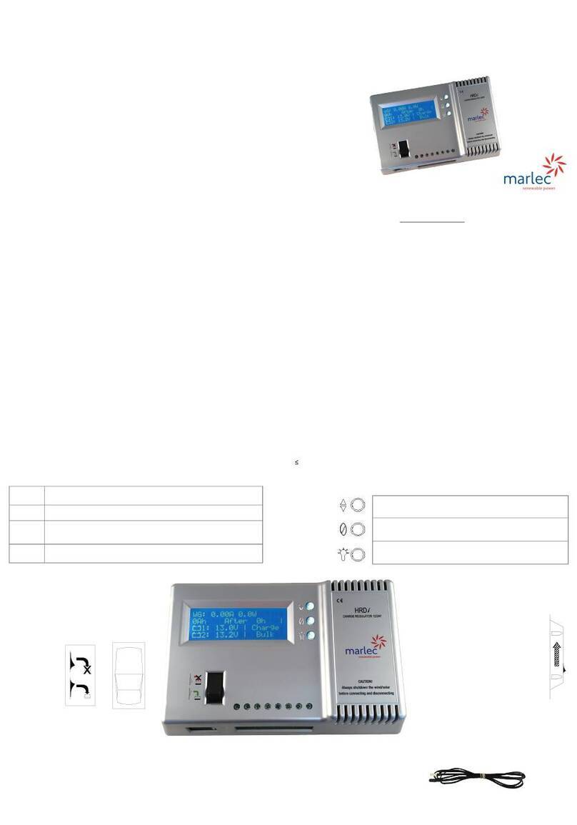
HRDiLayout & Main Features Congratulaons on purchasing Marlec’s HRDiCharge Regulator.
This is the latest technology for over charge regulaon of Rutland wind turbines and
solar panels. It is designed for use with Rutland 50”X” and 91”X” series models and
≤160Was of solar panels charging up to 2 separate baery banks.
Follow the installaon instrucons and operang guidance provided in this manual.
Line 1: Displays Amps and Wasbeing generated.
Scroll to view WG or PV or NET
Line 2: Logged Ampere hours generated aer elapsed hours
Line 3: Baery 1 voltage or LOW if <11.7V (23.4V)
Line 4: Baery 2 voltage or LOW if <11.7V (23.4V) or N/C not
connected.
LCD screen displays monitored data:
Baery
Symbols 1 & 2 Indicate approximate charge levels and flash when operang
inregulaonmode.
Scroll - to view WG (turbine) or PV (solar) or NET
readings. Screen can remain in any posion.
Zero - Press to reset logged Ah and follow the prompts
Backlight - ON/OFF. Default ON for 60 seconds
To enter programming mode press and hold for 3 seconds.
Quick Start Guide
The sequence of connecon is crical to the voltage set up of the HRDi. Follow
these instrucons carefully to ensure no connecons are live during installaon.
1. Select a covered, dry, vercal wall locaon in a venlated area close to the
baeries. Fix the HRDi using four suitable screws with the wiring block downmost.
Fit the external temperature sensor into its port and place the sensor p in the
vicinity of the baeries. If the sensor is not connected the temperature
compensaon feature is disabled. (Not recommended)
2. Select and prepare cables and connectors rated to connuously carry a minimum
of 10 Amps, no less than 4mm² gauge cable, to link the HRDito each baery. Keep
lengths to a minimum to avoid voltage drop and ensure accurate voltage sensing.
The maximum recommended length is 1.5m.
3. Cauon!
• Set the HRDiCharge / Stop switch to the Stop posion.
• Cover any solar panels and restrain the Windcharger from turning.
• Ensure that any other charge sources to the baery are stopped.
4. Connect the baery link cables to the HRDibaery posions BAT1 and BAT2 if
used but do not connect to the baeries. In service BAT1 must remain connected
to provide the internal power to the HRDi.
5. Connect the 2 Windcharger cables to the WG + & WG - posions and the solar
panel cables to the PV + & PV - posions ensuring correct polarity is observed or
damage will occur. Note : Solar panels must be fied with appropriate blocking
diodes, parallel panels having one each. Keep the solar panels covered and
Windcharger restrained.
6. Connect the other ends of the baery link cables directly onto the baery
terminals + & - of BAT2 first (if used) followed by BAT1, ensuring correct polarity.
The HRDi senses the baery voltage and establishes 12V or 24V operaon.
7. The LCD displays an inialisaon then the connecon status report. Check this
corresponds to your system:
8. Press Connue > (back light buon) or wait 10 seconds for the operang screen
to display.
9. Move the Charge / Stop switch to the Charge posion, uncover any solar panels
and untether the Rutland Windcharger.
The system is now fully operaonal.
User Guidance & Warnings
•Wind & Solar Panel connecons should never be made live or damage will
result. Restrain the turbine or cover the solar panel to prevent power generaon
before connecng to the controller.
•Do not disconnect from the baery unless the Stop switch is acvated.
Reconnect the baery before seng to Charge.
•During installaon or maintenance set the switch to the Stop posion.
•Do not use the Stop switch as a brake. If possible first orient the turbine to a
downwind posion to reduce rotaon and apply the switch to avoid shock loads
that can damage the controller.
•The HRDi must be connected directly onto the baery. On-board baery
management systems must not be allowed to break this connecon.
•SolarPVPanels—do not exceed the 160W maximum rated input. Note : in
ambient temperatures >40°C the solar panel input must be de-rated.
•In high levels of auxiliary charge, eg from an engine, the HRDimay enter
regulang mode and the windcharger will run at a slow speed.
• The logging feature of the HRDirecords up to 9999Ah before automacally
returning to zero if not reset by user in the meanme.
• Latest sengs are retained in the HRDi memory when it is disconnected.
Reconnecon re-acvates the sengs.
• Reprogramming of the Max V/Cell @ 25°C,(bulk,float and regulaon),
temperature compensaon and shutdown may be necessary when using non
lead-acid baeries. Check the baery manufacturer’s advice and contact Marlec
for delas of the PC App and Marlec Controller Interface Lead.
Operang Principles
The HRDiRegulator protects baeries from overcharge. It uses Pulse Width
Modulaon and mul-stage charge technology to maximise the power delivered
to and retained in the baery.
In the bulk/absorpon phaseall the available wind and solar power is used to
charge the baery as quickly as possible. The float phaseensures charge is
maintained whilst minimising gassing thus prolonging baery life. Some
discharging of the baery recommences this cycle.
The temperature compensaon feature automacally adjusts the voltage
regulaon sengs according to deviaons of ambient temperature from 25°C.
The pre-programmed sengs are suitable for lead acid, AGM (absorbed glass
ma) and most Gel type baeries. Default sengs are:
Nominal Baery Voltage @ 25°C 12V 24V
Maximum FloatVoltage @ 25°C 13.8V 27.6V
Maximum Bulk Voltage @ 25°C 14.4V 28.8V
System Voltage xxV
Baery 2 Connected or Not Fied
External Temp or No Temp Sensor
If thestatus report doesnot
correspond to your system
disconnect thebaeries and restart
theprocedure.
Wiring Schemac - HRDi Controller
(Oponal)

This manual suits for next models

1

Other Marlec Controllers manuals

Marlec Solar iBoost+ User manual

Marlec

Marlec Solar iBoost+ User manual

Marlec HRDi Owner's manual

Marlec

Marlec HRDi Owner's manual

Marlec HRDi Guide

Marlec

Marlec HRDi Guide

Marlec Solar iBoost+ User manual

Marlec

Marlec Solar iBoost+ User manual

Marlec CA-11/46 Guide

Marlec

Marlec CA-11/46 Guide

Popular Controllers manuals by other brands

M-system PSP10 instruction manual

M-system

M-system PSP10 instruction manual

ActronAir QUE QZW-100 Installation and user manual

ActronAir

ActronAir QUE QZW-100 Installation and user manual

Aube Technologies TH146-P-2H1C installation guide

Aube Technologies

Aube Technologies TH146-P-2H1C installation guide

Azoteq IQ Switch - ProxSense Series Design guide

Azoteq

Azoteq IQ Switch - ProxSense Series Design guide

Quantum Rehab Q-Logic 2 Basic operation instructions

Quantum Rehab

Quantum Rehab Q-Logic 2 Basic operation instructions

Eurotherm 2132 operating instructions

Eurotherm

Eurotherm 2132 operating instructions

Calsense CS3000 quick start guide

Calsense

Calsense CS3000 quick start guide

Kyocera LYNCOM N25T datasheet

Kyocera

Kyocera LYNCOM N25T datasheet

EVERSPRING AN188 quick start guide

EVERSPRING

EVERSPRING AN188 quick start guide

Fiery X3eTY 35C-KM user guide

Fiery

Fiery X3eTY 35C-KM user guide

NT KN303 user manual

NT

NT KN303 user manual

X10 KR22A user manual

X10

X10 KR22A user manual

Blonder tongue NXG SYSTEM KIT user manual

Blonder tongue

Blonder tongue NXG SYSTEM KIT user manual

Autonics 1-Axis High Speed Stand-Alone Series user manual

Autonics

Autonics 1-Axis High Speed Stand-Alone Series user manual

Emec Centurio PRO operating manual

Emec

Emec Centurio PRO operating manual

Siemens GD Series Mounting instructions

Siemens

Siemens GD Series Mounting instructions

Tate SmartAire M Guide

Tate

Tate SmartAire M Guide

Watts Lync AEGIS user manual

Watts

Watts Lync AEGIS user manual

manuals.online logo
manuals.online logoBrands
  • About & Mission
  • Contact us
  • Privacy Policy
  • Terms and Conditions

Copyright 2025 Manuals.Online. All Rights Reserved.